Axial and lateral stiffness of spherical self-balancing fiber reinforced rubber pipes under internal pressure
-
Guo-min Xu


Abstract
Fiber reinforced rubber pipes are widely used to transport fluid at locations requiring flexible connections in pipeline systems. The spherical self-balancing fiber reinforced rubber pipes with low stiffness are drawing attention because of their vibration suppression performance under high internal pressure. In this paper, a theoretical model is proposed to calculate the axial stiffness and lateral stiffness of spherical self-balancing fiber reinforced rubber pipes. The inhomogeneous anisotropy of the reinforced layer and the nonlinear stress-strain relationship of the reinforced fiber are considered in the model. The accuracy of the model is verified by experimental results. Theoretical calculation finds that both the axial and lateral stiffness are influenced significantly by the key structural parameters of the pipe (the axial length, the circumferential radius at the end, the meridional radius, and the initial winding angle). The stiffness can be reduced remarkably with optimal meridional radius and initial winding angle, without any side effect on the self-balance of the pipe. The investigation methods and results presented in this paper will provide guidance for design of fiber reinforced rubber pipes in the future.
1 Introduction
Fiber reinforced rubber pipes are widely used to transport fluid at locations requiring flexible connection in pipeline system. They protect the pipeline from damage caused by mechanical vibration and shock, proved extremely useful in marine engineering. The pipes are composed of inner rubber layer, reinforced layer and outer rubber layer, as shown in Figure 1. The reinforced layer is fabricated by multi-layer helically wound unidirectional fabric. With the development of vibration isolation technology for marine engineering, the vibration isolation performance of the float raft system has been greatly improved in recent years. Instead, the propagation of vibration along the pipeline system has been increasingly prominent, becoming one of the key challenges for vibration control of ships [1]. The spherical self-balancing rubber pipes with low stiffness are drawing attention because of their good vibration suppression performance under high internal pressure in pipeline systems. In practical applications, rubber pipes are required to be self-balancing under internal pressure. A rubber pipe with poor balance will produce additional deformation and unbalanced force, damaging the pipelines connected upstream and downstream under high internal pressure. Therefore, the stiffness characteristics of spherical fiber reinforced rubber pipes with good balance needs to be carefully investigated.

The cross-section of the fiber reinforced rubber pipe.
The stiffness of fiber reinforced pipes has been investigated in depth. Jaszak et al. [2] analyzed the stress distribution of rubber pipes under internal pressure with finite element analysis based on the Mooney-Rivlin model of the rubber material, concluding that the influence of elastic properties of the rubber layer on the stress distribution is negligible. Therefore, the stiffness is mainly determined by the geometry of the rubber pipes and the anisotropy of the reinforced layer. The axial stiffness of cylindrical self-balancing rubber pipes was investigated based on the anisotropic shell theory [3, 4]. Zhou et al. [5] calculated the axial stiffness of spherical rubber pipe based on the thin shell theory, but did not consider the anisotropy of the reinforced layer on the stiffness characteristics. Gao et al. [6] established the axial stiffness model of spherical self-balancing rubber pipes based on anisotropic membrane theory, considering the winding angle variance of rubber pipes under high internal pressure. It should be noted that the balance of pipes could be achieved by specific winding angle of the unidirectional fabric. The self-balancing angle of cylindrical pipes is near 55 degrees [7,8,9], while the self-balancing angle of spherical pipes is determined by the geometry of the pipe [10]. A number of investigations paid attention to the lateral stiffness of fiber reinforced pipes under internal pressure. Chen et al. [11] studied the lateral stiffness of rubber pipes with an equivalent beam model fixed at both ends. Rafiee et al. [12] established theoretical model to estimate the lateral stiffness of fiber reinforced rubber pipes based on the back-of-envelope technique.
As already known from the research above mentioned, the stiffness of fiber reinforced rubber pipes has gained sufficient attention. However, the stiffness of the spherical self-balancing fiber reinforced rubber pipes needs deeper investigations. Firstly, the comprehensive research on both the axial stiffness and the lateral stiffness is deficient. Reducing the axial stiffness alone will cause the rise of the lateral stiffness possibly and vice versa. To improve the vibration suppression performance of the rubber pipes, the axial stiffness and lateral stiffness are supposed to be optimized together. Secondly, most research is limited to cylindrical fiber reinforced pipes. For spherical pipes, the anisotropy distribution of the reinforced layer is more complicated. The spherical fiber reinforced rubber pipes are manufactured with the curing process, as shown in Figure 2. The reinforced layer is fabricated with unidirectional fabric cross winding helically at a specific initial winding angle before the rubber pipes expanded to the preset shape. The winding angle is determined by the meridian shape on the spherical pipes, while the winding angle is homogeneous on the cylindrical pipes. Therefore, the nonlinear distribution of winding angle leads to inhomogeneous anisotropy of the reinforced layer on the spherical pipes. Thirdly, the variance of the elastic modulus of the reinforce fiber is not negligible when the rubber pipe is subject to different internal pressure. Rao et al. [13] and Kumar et al. [14] found that the reinforced fiber has a nonlinear stress-strain relationship in cord/rubber composites. In the stage with small strain, the elastic modulus of the fiber changes with the strain. In the stage with intermediate strain, the elastic modulus tends to be constant. It could bring extra error in the theoretical model without considering the nonlinear stress-strain relationship of the reinforced fiber.
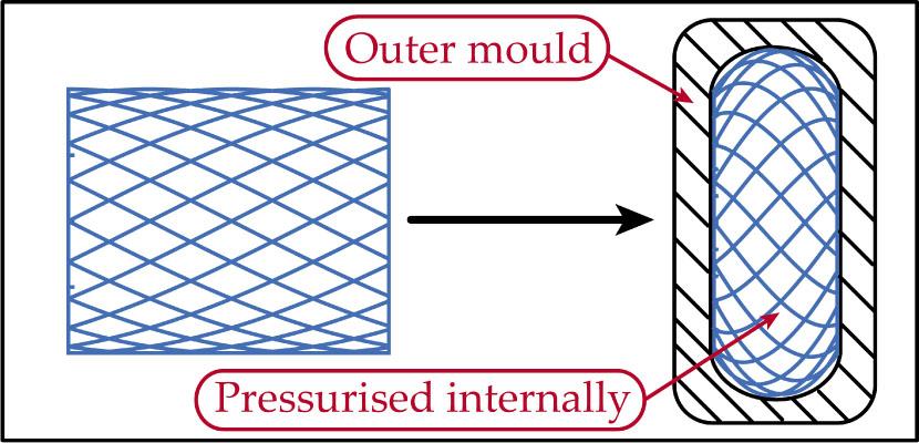
The curing process of spherical fiber reinforced rubber pipes.
In this paper, the axial stiffness and lateral stiffness of spherical self-balancing fiber reinforced rubber pipes are investigated based on the anisotropic membrane theory and the composite Timoshenko beam theory, respectively. The inhomogeneous anisotropy of the reinforced layer and the nonlinear stress-strain relationship of the fiber are considered in the theoretical model. The key structural parameters of the spherical pipe are the axial length, the circumferential radius at the ends, the meridional radius and the initial winding angle. Influences of these parameters on the distribution of winding angle, the anisotropy of the reinforced layer, the axial stiffness and the lateral stiffness are investigated in detail. The calculated results of the axial stiffness and the lateral stiffness are in good agreement with the experiment results, proving the accuracy of the theoretical model. To improve the vibration suppression performance, the stiffness characteristics are optimized with adjusting the meridional radius and the initial winding angle. The investigation methods and results presented in this paper will provide guidance for design of fiber reinforced rubber pipes in the future.
2 Theoretical analysis
2.1 Material model of the reinforced layer
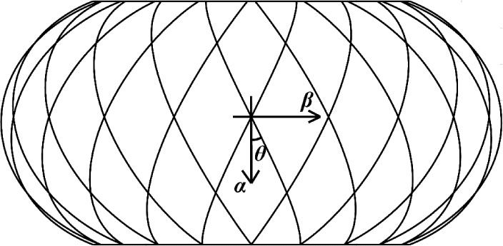
The geometric model of the spherical pipe is shown in Figure 3. A curvilinear coordinate system (α, β, γ) and a Cartesian coordinate system (x, y, z) are established. The geometry of the spherical pipe is simply determined by the structure vector H = [L, r, Rα, θ0]T, where L, r, Rα and θ0 represents the axial length, the circumferential radius at the end, the meridional radius, and the initial winding angle, respectively.

The geometric model of the spherical pipe. (a) The curvilinear coordinate system and the Cartesian coordinate system. (b) The structural parameters of the spherical pipe.
The winding angle of the reinforced layer.
The single-layer cord/rubber lamina can be regarded as orthotropic material [15]. The equivalent elastic constants of the lamina can be obtained with the following equations [16]
where Ec and Er are the Elastic modulus of the cord and rubber, respectively; μc and μr are the Poisson's ratios of the cord and rubber, respectively; Gc and Gr is the shear modulus of the cord and rubber, respectively; Vc is the volume fraction of cord. The stress-strain relations of the kth lamina in the reinforced layer are written as [17]
where
where
where
where winding angle θ is the angle between direction 1 of the fiber and the direction α of the curvilinear coordinate system, as shown in Figure 3.
The anisotropy of the reinforced layer are closely related to the local winding angle of the fabric. Although the initial winding angle is uniform, the winding angle of expanded reinforced layer keeps changing at different positions along the meridional direction. For the curing process, the following two assumptions are proposed:
The cords of the fabric is not stretched during the curing process;
Both ends of the pipe do not rotate relatively to each other during the curing process.
Supposing the initial winding angle is θ0, the geometric relationship established based on the assumptions abovementioned are written as
where Rβ represents the circumferential radius, as shown in Figure 3. The distribution of the winding angle θ along the meridional direction derived from equations (6) is
The structure vector H has significant influence on the distribution of winding angle. Figure 5 shows that the winding angle of cord fabric will become more non-uniform along the axial direction when the initial winding angle and axial length increase, and when the circumferential radius at the end and the meridional radius decrease.
![Figure 5 Distribution of winding angle at different H. The initial structure vector H0 = [0.1, 0.1, 0.1, 40]: (a) varied initial winding angles θ0; (b) varied axial lengths L; (c) varied circumferential radius at the ends r; (d) varied meridional radius Rα.](/document/doi/10.1515/secm-2021-0009/asset/graphic/j_secm-2021-0009_fig_005.jpg)
Distribution of winding angle at different H. The initial structure vector H0 = [0.1, 0.1, 0.1, 40]: (a) varied initial winding angles θ0; (b) varied axial lengths L; (c) varied circumferential radius at the ends r; (d) varied meridional radius Rα.
The stress-strain relationship is used to obtain the elastic constant along the axial direction of the rubber pipe:
The distribution of the elastic constants is shown in Figure 6a. At any position of the pipe, the shear modulus is greater than the meridional and latitudinal elastic modulus. At the center of the joint, the meridional elastic modulus reaches the minimum value, while the latitudinal elastic modulus reaches a maximum value. Figure 6b shows the relative variance of the elastic constants with different winding angle. The off-axis elastic constants reduce to the orthotropic properties when the winding angle equals 0 degree and 90 degrees. The shear modulus reaches the maximum when the winding angle equals 45 degrees. The stiffness matrix of the 1500D/3-type aramid cords is used in the theoretical calculation, written as follows [15].
![Figure 6 (a) Distribution of elastic constants with the structure vector H = [0.1, 0.1, 0.1, 40]. (b) The elastic constants at variant winding angle.](/document/doi/10.1515/secm-2021-0009/asset/graphic/j_secm-2021-0009_fig_006.jpg)
(a) Distribution of elastic constants with the structure vector H = [0.1, 0.1, 0.1, 40]. (b) The elastic constants at variant winding angle.
The rubber pipes are reinforced by multi-layer fabric. Based on the composite Reissner shell theory, the stiffness matrix of the reinforced layer is
where N and M are the inplane force and bending moment, respectively; €0 is the strain in the midsurface of the reinforced layer; κ is the curvature and torsion ratio of the midsurface. Each sub-matrix of the stiffness matrix is defined as [18]
2.2 Analysis of the axial stiffness
The inplane force is defined as
where δ is the thickness of the reinforced layer. Under the assumption of thin shell theory, the thickness of the reinforced layer is a small quantity, so the terms related to thickness are considered as high-order small quantities and are negligible in equation (12). Without considering the bending moment and shear force, the geometric equation is simplified as follows [17]
where A, B are lamé parameters and kα, kβ are principal curvature of the midsurface. Combining equations (12) and (13), yields
The equilibrium equations [17] are
The spherical pipe is an axisymmetric shell of revolution, so the coefficients in equations (14) and (15) are
where p is internal pressure. It is assumed that all the constraints and external loads are axisymmetric, and then for any point of the pipe, the equilibrium equation is established in the meridional direction as follows
The axial stiffness of the deformation of joint body is determined by the relationship between Fy and the axial deformation y. Combining equations (14), (15) and (17), the solutions of internal force and displacement are obtained as follows
where C1 is an integral constant determined by boundary conditions. The boundary condition is
Substituting equations (18) into equation (19) yields the force-displacement relationship for the axial deformation:
The influences of structural parameters are then computed on the axial stiffness, as shown in Figure 7. The axial stiffness will increase significantly when the initial winding angle increases, the meridional radius increases, the axial length decreases, and the circumferential radius at the end increases.
![Figure 7 Axial stiffness at different H, and the initial structure vector H0 = [0.1, 0.1, 0.1, 40]: (a) varied initial winding angle θ0; (b) varied meridional radii Rα; (c) varied axial lengths L; (d) varied circumferential radii at the ends r.](/document/doi/10.1515/secm-2021-0009/asset/graphic/j_secm-2021-0009_fig_007.jpg)
Axial stiffness at different H, and the initial structure vector H0 = [0.1, 0.1, 0.1, 40]: (a) varied initial winding angle θ0; (b) varied meridional radii Rα; (c) varied axial lengths L; (d) varied circumferential radii at the ends r.
Aramid fiber is generally used as the cord material for large-diameter rubber pipes resistant to high pressure. The elastic modulus of aramid fiber has strong nonlinearity even in the low-stress stage, so it is necessary to experimentally obtain the variation of the elastic modulus of aramid cord with the cord stress. The distribution of stress in the reinforced layer is
With the formula of off-axis stress, the stress along the direction of cords σ1 is obtained as follows:
where θ is the winding angle of cords. The elastic modulus of cords under different stresses can be obtained by processing the measured force-displacement data of cords. Substituting this elastic modulus into the theoretical model of stiffness yields the stiffness characteristics of the rubber pipe under different internal pressures.
2.3 Analysis of the lateral stiffness
Based on the Timoshenko beam theory, a model is established to calculate the lateral stiffness of the spherical fiber reinforced pipes. The deflection equation of beam is [19]
where a is the shear coefficient, q is the load, EI is the bending stiffness, and GA is the shear stiffness. The thickness of the tube is thinner than that of the inner diameter, so the shear stress is approximately uniformly distributed in the thickness direction, and the shear coefficient a equals 1. According to Shadmehri et al. [20], the bending stiffness of a composite pipe is
where Ro,n and Ri,n are the outer diameter and inner diameter of the nth layer of fiber, respectively; En is the axial elastic modulus of the nth layer, and can be calculated as follows:
The influences of the initial winding angle and the meridional radius are analyzed on the spatial distributions of bending stiffness and shear stiffness, as shown in Figure 8. When the initial winding angle is 43 degree, the bending stiffness and shear stiffness reach their minimum and maximum values, respectively.
![Figure 8 For an initial structure vector H0 = [0.1, 0.1, 0.1, 40], a) distribution of bending stiffness at different θ0; b) distribution of shear stiffness at different θ0; c) distribution of bending stiffness at different meridional radii; d) distribution of shear stiffness at different meridional radii.](/document/doi/10.1515/secm-2021-0009/asset/graphic/j_secm-2021-0009_fig_008.jpg)
For an initial structure vector H0 = [0.1, 0.1, 0.1, 40], a) distribution of bending stiffness at different θ0; b) distribution of shear stiffness at different θ0; c) distribution of bending stiffness at different meridional radii; d) distribution of shear stiffness at different meridional radii.
Because of the non-uniformity of the distribution of bending stiffness and shear stiffness, the equation is transformed into a difference equation to obtain the numerical solution of deflection. Based on the definition of central difference, the difference equation deflection curve is obtained:
where h is the length step of difference. In this paper, the influences of structural parameters are analyzed on the lateral stiffness of a rubber pipe with Clamped-Clamped boundary condition, and the calculated results are shown in Figure 9. The result reveals that the lateral stiffness will significantly decrease when the winding angle and axial length increase and the circumferential radius decreases.
![Figure 9 Lateral stiffness at different H, and the initial structure vector H0 = [0.1, 0.1, 0.1, 40]: (a) varied initial winding angles θ0; (b) varied meridional radii Rα; (c) varied axial lengths L; (d) varied circumferential radii at the ends r.](/document/doi/10.1515/secm-2021-0009/asset/graphic/j_secm-2021-0009_fig_009.jpg)
Lateral stiffness at different H, and the initial structure vector H0 = [0.1, 0.1, 0.1, 40]: (a) varied initial winding angles θ0; (b) varied meridional radii Rα; (c) varied axial lengths L; (d) varied circumferential radii at the ends r.
2.4 The self-balance of spherical fiber reinforced rubber pipes
A rubber pipe used in ship pipeline systems is required to have good self-balance; otherwise, when the internal pressure changes, the pipe will produce additional deformation and may damage the connected pipeline or equipment. Self-balance is evaluated by the following indexes: 1) unbalanced displacement, which is defined as the ratio of length change under the working pressure when both ends are free; 2) unbalanced force: the reaction force under the working pressure when both ends are fixed. The methods are derived for solving the ratio of length change and reaction force:
When both ends are free, calculate the ratio of length change under the working pressure. Based on the geometric relationship, the axial deformation y of joint body is calculated as follows:
(27)It is combined with equation (20), and let the external force in the axial direction Fy equal 0, and then the ratio of length change can be calculated:
(28)When both ends of the pipe are clamped, the unbalanced force is calculated under the working pressure. In formula (20), let the axial deformation y be equal to 0, and the reaction force can be obtained when both ends of the pipe body are fixed:
(29)The approach of stiffness calculation of self-balancing fiber reinforced rubber pipes is summarized in a flow chart in Figure 10.
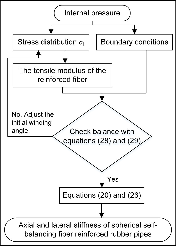
The approach of stiffness calculation of self-balancing fiber reinforced rubber pipes.

(a) Experimental systems used to measure the axial and lateral stiffness; (b) tensile test of aramid cords; (c) axial stiffness test; (d) lateral stiffness test.
3 Experiment results
Experiments are conducted to obtain the variation of the elastic modulus of aramid cord with the cord stress in section 3.1, because the elastic modulus of aramid fiber has strong nonlinearity even in the low-stress stage. The axial and lateral stiffness of four types of spherical self-balancing rubber pipes are also measured in section 3.2, and the measured results are compared with the resulted calculated with the proposed model.
There are four types of self-balanced spherical rubber pipes with different specifications but the same rated working pressure of 3.0MPa. The main structural parameters are shown in Table 1, and the model of test device and the test layout are shown in Table 2 and Figure 10, respectively.
Parameters of the tested rubber pipes.
| model | L (mm) | r (mm) | Rα (mm) | θ0 () |
|---|---|---|---|---|
| DN50 | 83 | 32 | 82 | 36 |
| DN100 | 127 | 59 | 125 | 38 |
| DN125 | 95 | 71 | 93 | 40 |
| DN150 | 102 | 84 | 100 | 39 |
Experimental device list.
| Device | Model |
|---|---|
| Mechanical test system | MTS landmark 370.50 |
| Water pump | 40sy-15/80 |
| Pressure gauge | ACD-201 |
| Accumulator | NXQAB-80-10-L-Y |
3.1 The elastic modulus of aramid cord
Table 3 shows the properties of the aramid cords used in the research. Based on the measured data of tensile test, the fitting results of the elastic modulus of cord are obtained with the least square method and are shown in Figure 12. When the cord strain is less than 0.01, the elastic modulus increases with the increase of the strain; when the strain is greater than 0.01, the elastic modulus becomes linear.
Properties of cord/rubber layer.
| Component | Property | |
|---|---|---|
| Cord | Material | Aramid |
| Construction | 1140D/2 | |
| Diameter | 0.8 mm | |
| E1 | 21 GPa | |
| Rubber | Elastic modulus | 6 MPa |
| Cord/Rubber Layer | Thickness | 1.1 mm |

The stress-strain relationship of 1140D/2 aramid cords.
3.2 Axial and lateral stiffness of the rubber pipes
The aforementioned stiffness model is used to derive the axial and lateral stiffness of rubber pipes with four different sizes, and the results are shown in Figure 13a and Figure 13b. The theoretical results are in good agreement with the experimental results, suggesting that the stiffness model obtained in this paper can accurately describe the axial and lateral stiffness of the rubber pipes.

(a) Calculated and measured axial stiffness vs internal pressure; (b) calculated and measured lateral stiffness vs internal pressure.
4 Discussion
The experimental result in Figure 13 suggests that the lateral stiffness is larger than the axial stiffness of the tested rubber pipes. In order to reduce the lateral stiffness without causing a significant increase in the axial stiffness, the meridional radius and initial cord-winding angle are varied simultaneous in the theoretical while the self-balance of the rubber pipe is maintained. The problem is to reduce the maximum stiffness of the rubber pipe (i.e. the larger value in the axial stiffness and lateral stiffness) under the following conditions: 1) the internal pressure is kept at 3.0MPa; 2) the variation of the axial length of joint body is less than 1%; 3) the unbalance force is less than the external axial force required to produce 1% change in the axial length. The constraints of optimization are summarized as
where Φ is the objective function of the optimization, kaxial represents the axial stiffness and klateral represents the lateral stiffness.
Table 4 shows the results of structural-parameter optimization, Table 5 compares the results obtained before and after stiffness optimization, and Figure 14 shows the calculated variations of axial and lateral stiffness with different meridional radius. The data in Table 4 reveals that the optimization of structural parameters does not affect the self-balance of the original rubber pipes. The results in Figure 14 suggest that the optimal meridional radius and initial winding angle can be obtained through simultaneous adjustment of both parameters. The result in Table 5 suggests that the lateral stiffness can be reduced by 19.5% with the optimal structural parameters.
Optimized parameters of rubber pipes.
| Model | L, mm | r, mm | Rα, mm | θ0, | ΔF, N |
|---|---|---|---|---|---|
| DN50 | 83 | 32 | 85 | 36.8 | −24.8 |
| DN100 | 127 | 59 | 135 | 38.6 | −100.1 |
| DN125 | 95 | 71 | 175 | 44.1 | 136.4 |
| DN150 | 102 | 83 | 133 | 42.6 | 59.4 |
Optimization results of axial and lateral stiffness.
| model | Original Stiffness, kN/mm | Optimized Stiffness, kN/mm | Reduction rate of lateral stiffness | ||
|---|---|---|---|---|---|
| Axial | Flexural | Axial | Flexural | ||
| DN50 | 1.22 | 1.93 | 1.58 | 1.57 | 18.7% |
| DN100 | 2.81 | 3.95 | 3.22 | 3.24 | 18.0% |
| DN125 | 4.24 | 7.09 | 5.55 | 5.56 | 21.6% |
| DN150 | 6.82 | 9.43 | 7.53 | 7.55 | 19.9% |
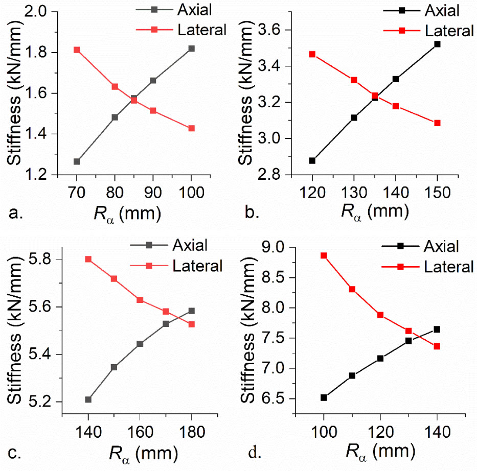
a) Calculated stiffness vs meridional radius of DN50; b) calculated stiffness vs meridional radius of DN100; c) calculated stiffness vs meridional radius of DN125; d) calculated stiffness vs meridional radius of DN150.
5 Conclusion
The theoretical model is proposed to calculate the axial stiffness and the lateral stiffness of spherical self-balancing fiber reinforced rubber pipes. The accuracy of the theoretical model is verified by the experiment of axial stiffness and lateral stiffness. The theoretical calculation finds that both the axial and lateral stiffness are influenced significantly by the key structural parameters of the pipe (the axial length, the circumferential radius at the end, the meridional radius, and the initial winding angle). The stiffness of the spherical self-balancing fiber reinforced rubber pipes has a remarkable decrease with optimal meridional radius and initial winding angle without any side effect on the self-balance. The investigation methods and results presented in this paper will provide guidance for design of fiber reinforced rubber pipes in the future.
References
[1] He, L., Development of submarine acoustic stealth technology. Ship Science and Technology. 2007, 9, 29–42.Search in Google Scholar
[2] Jaszak, P., Skrzypacz, J., and Adamek, K., The design method of rubber-metallic expansion joint. Open Eng. 2018, 8, 532.10.1515/eng-2018-0065Search in Google Scholar
[3] van den Horn, B.A. and Kuipers, M., Strength and stiffness of a reinforced flexible hose. Appl. Sci. Res. 1988, 45, 251–281.10.1007/BF00384690Search in Google Scholar
[4] Park, J.-S., et al., Pipe Stiffness Prediction of Buried Gfrp Flexible Pipe. Polym. Polym. Compos. 2014, 22, 17–24.10.1177/096739111402200103Search in Google Scholar
[5] Zhou, W., He, l., and Gu, T., Parameterized calculation method for static performance of a flexible arc pipe. J. Vib. Shock. 2009, 28, 214–216.Search in Google Scholar
[6] Gao, H., Shuai, C.G., and Xu, G.M., Study on Mechanical Model of Balance and Stiffness Characteristics of Fiber Reinforced Bellows Type Rubber Hose. Sci. Adv. Mater. 2020, 12, 981–993.10.1166/sam.2020.3735Search in Google Scholar
[7] Zhou, Y., et al., Theoretical analysis of reinforcement layers in bonded flexible marine hose under internal pressure. Eng. Struct. 2018, 168, 384–398.10.1016/j.engstruct.2018.04.061Search in Google Scholar
[8] Geng, P., Xing, J.Z., and Chen, X.X., Winding angle optimization of filament-wound cylindrical vessel under internal pressure. Archive of Applied Mechanics. 2017, 87, 365–384.10.1007/s00419-016-1198-5Search in Google Scholar
[9] Soden, P.D., et al., Influence of winding angle on the strength and deformation of filament-wound composite tubes subjected to uniaxial and biaxial loads. Compos. Sci. Technol. 1993, 46, 363–378.10.1016/0266-3538(93)90182-GSearch in Google Scholar
[10] Zhang, X., He, l., and Zhou, W., Equilibrium performance of a filament-wound flexible arc pipe. J. Vib. Shock. 2012, 31, 70–73.Search in Google Scholar
[11] Chen, Y., et al., Transverse impact characteristics of a rubber pipe expansion joint. Journal of Mechanical Science and Technology. 2012, 26, 1655–1661.10.1007/s12206-012-0415-6Search in Google Scholar
[12] Rafiee, R. and Habibagahi, M.R., On The Stiffness Prediction of GFRP Pipes Subjected to Transverse Loading. KSCE Journal of Civil Engineering. 2018, 22, 4564–4572.10.1007/s12205-018-2003-5Search in Google Scholar
[13] Rao, S., Daniel, I.M., and Gdoutos, E.E., Mechanical Properties and Failure Behavior of Cord/Rubber Composites. Appl. Compos. Mater. 2004, 11, 353–375.10.1023/B:ACMA.0000045312.61921.1fSearch in Google Scholar
[14] Kumar, M. and Bert, C., Experimental characterization of mechanical behavior of cord-rubber composites. Tire Science and Technology. 1982, 10, 37–54.10.2346/1.2150974Search in Google Scholar
[15] Cembrola, R. and Dudek, T., Cord/rubber material properties. Rubber Chem. Technol. 1985, 58, 830–856.10.5254/1.3536096Search in Google Scholar
[16] Walter, J.D., Cord—Rubber Tire Composites: Theory and Applications. Rubber Chem. Technol. 1978, 51, 524–576.10.5254/1.3535749Search in Google Scholar
[17] Qatu, M.S., Vibration of laminated shells and plates. Elsevier, 2004.10.1016/B978-008044271-6/50006-5Search in Google Scholar
[18] Bert, C.W., Structural Theory for Laminated Anisotropic Elastic Shells. J. Compos. Mater. 1967, 1, 414–423.10.1177/002199836700100409Search in Google Scholar
[19] Gere, J.M. and Timoshenko, S.P., Mechanics of materials. Chapman and Hall, 1998.Search in Google Scholar
[20] Shadmehri, F., Derisi, B., and Hoa, S.V., On bending stiffness of composite tubes. Compos. Struct. 2011, 93, 2173–2179.10.1016/j.compstruct.2011.03.002Search in Google Scholar
© 2021 Guo-min Xu et al., published by De Gruyter
This work is licensed under the Creative Commons Attribution 4.0 International License.
Articles in the same Issue
- Effects of Material Constructions on Supersonic Flutter Characteristics for Composite Rectangular Plates Reinforced with Carbon Nano-structures
- Processing of Hollow Glass Microspheres (HGM) filled Epoxy Syntactic Foam Composites with improved Structural Characteristics
- Investigation on the anti-penetration performance of the steel/nylon sandwich plate
- Flexural bearing capacity and failure mechanism of CFRP-aluminum laminate beam with double-channel cross-section
- In-Plane Permeability Measurement of Biaxial Woven Fabrics by 2D-Radial Flow Method
- Regular Articles
- Real time defect detection during composite layup via Tactile Shape Sensing
- Mechanical and durability properties of GFRP bars exposed to aggressive solution environments
- Cushioning energy absorption of paper corrugation tubes with regular polygonal cross-section under axial static compression
- An investigation on the degradation behaviors of Mg wires/PLA composite for bone fixation implants: influence of wire content and load mode
- Compressive bearing capacity and failure mechanism of CFRP–aluminum laminate column with single-channel cross section
- Self-Fibers Compacting Concrete Properties Reinforced with Propylene Fibers
- Study on the fabrication of in-situ TiB2/Al composite by electroslag melting
- Characterization and Comparison Research on Composite of Alluvial Clayey Soil Modified with Fine Aggregates of Construction Waste and Fly Ash
- Axial and lateral stiffness of spherical self-balancing fiber reinforced rubber pipes under internal pressure
- Influence of technical parameters on the structure of annular axis braided preforms
- Nano titanium oxide for modifying water physical property and acid-resistance of alluvial soil in Yangtze River estuary
- Modified Halpin–Tsai equation for predicting interfacial effect in water diffusion process
- Experimental research on effect of opening configuration and reinforcement method on buckling and strength analyses of spar web made of composite material
- Photoluminescence characteristics and energy transfer phenomena in Ce3+-doped YVO4 single crystal
- Influence of fiber type on mechanical properties of lightweight cement-based composites
- Mechanical and fracture properties of steel fiber-reinforced geopolymer concrete
- Handcrafted digital light processing apparatus for additively manufacturing oral-prosthesis targeted nano-ceramic resin composites
- 3D printing path planning algorithm for thin walled and complex devices
- Material-removing machining wastes as a filler of a polymer concrete (industrial chips as a filler of a polymer concrete)
- The electrochemical performance and modification mechanism of the corrosion inhibitor on concrete
- Evaluation of the applicability of different viscoelasticity constitutive models in bamboo scrimber short-term tensile creep property research
- Experimental and microstructure analysis of the penetration resistance of composite structures
- Ultrasensitive analysis of SW-BNNT with an extra attached mass
- Active vibration suppression of wind turbine blades integrated with piezoelectric sensors
- Delamination properties and in situ damage monitoring of z-pinned carbon fiber/epoxy composites
- Analysis of the influence of asymmetric geological conditions on stability of high arch dam
- Measurement and simulation validation of numerical model parameters of fresh concrete
- Tuning the through-thickness orientation of 1D nanocarbons to enhance the electrical conductivity and ILSS of hierarchical CFRP composites
- Performance improvements of a short glass fiber-reinforced PA66 composite
- Investigation on the acoustic properties of structural gradient 316L stainless steel hollow spheres composites
- Experimental studies on the dynamic viscoelastic properties of basalt fiber-reinforced asphalt mixtures
- Hot deformation behavior of nano-Al2O3-dispersion-strengthened Cu20W composite
- Synthesize and characterization of conductive nano silver/graphene oxide composites
- Analysis and optimization of mechanical properties of recycled concrete based on aggregate characteristics
- Synthesis and characterization of polyurethane–polysiloxane block copolymers modified by α,ω-hydroxyalkyl polysiloxanes with methacrylate side chain
- Buckling analysis of thin-walled metal liner of cylindrical composite overwrapped pressure vessels with depressions after autofrettage processing
- Use of polypropylene fibres to increase the resistance of reinforcement to chloride corrosion in concretes
- Oblique penetration mechanism of hybrid composite laminates
- Comparative study between dry and wet properties of thermoplastic PA6/PP novel matrix-based carbon fibre composites
- Experimental study on the low-velocity impact failure mechanism of foam core sandwich panels with shape memory alloy hybrid face-sheets
- Preparation, optical properties, and thermal stability of polyvinyl butyral composite films containing core (lanthanum hexaboride)–shell (titanium dioxide)-structured nanoparticles
- Research on the size effect of roughness on rock uniaxial compressive strength and characteristic strength
- Research on the mechanical model of cord-reinforced air spring with winding formation
- Experimental study on the influence of mixing time on concrete performance under different mixing modes
- A continuum damage model for fatigue life prediction of 2.5D woven composites
- Investigation of the influence of recyclate content on Poisson number of composites
- A hard-core soft-shell model for vibration condition of fresh concrete based on low water-cement ratio concrete
- Retraction
- Thermal and mechanical characteristics of cement nanocomposites
- Influence of class F fly ash and silica nano-micro powder on water permeability and thermal properties of high performance cementitious composites
- Effects of fly ash and cement content on rheological, mechanical, and transport properties of high-performance self-compacting concrete
- Erratum
- Inverse analysis of concrete meso-constitutive model parameters considering aggregate size effect
- Special Issue: MDA 2020
- Comparison of the shear behavior in graphite-epoxy composites evaluated by means of biaxial test and off-axis tension test
- Photosynthetic textile biocomposites: Using laboratory testing and digital fabrication to develop flexible living building materials
- Study of gypsum composites with fine solid aggregates at elevated temperatures
- Optimization for drilling process of metal-composite aeronautical structures
- Engineering of composite materials made of epoxy resins modified with recycled fine aggregate
- Evaluation of carbon fiber reinforced polymer – CFRP – machining by applying industrial robots
- Experimental and analytical study of bio-based epoxy composite materials for strengthening reinforced concrete structures
- Environmental effects on mode II fracture toughness of unidirectional E-glass/vinyl ester laminated composites
- Special Issue: NCM4EA
- Effect and mechanism of different excitation modes on the activities of the recycled brick micropowder