Experimental and analytical study of bio-based epoxy composite materials for strengthening reinforced concrete structures
-


Abstract
This paper presents a new approach to strengthen reinforced concrete structures using natural fiber composites. Natural fibers are often used in civil engineering for thermal or acoustic insulation, but rarely are they employed to strengthen structures. Natural fiber composites are constituted of a matrix based on epoxy adhesive and aligned continuous fiber reinforcements. In this study, we investigate several fibers (carbon, hemp, fiberglass, and linen) in tensile and bending tests. The bending results show twice the magnification of the ultimate bending load in a strengthened specimen. The study also evaluates the stress distribution in the structure. In the case of a beam strengthened by a bonded carbon plate, the functioning of an assembly single lap and the optimal anchor length was determined by analogy. The analytical study describes the shear and peel stresses in the adhesive, composite, and concrete joints, revealing the optimum values of shear stress near the ends of the adhesive joint. The same was observed in concrete. The tests showed the influence of strengthening on the ultimate load and stiffness as well as the concentration of shear stresses at the ends of the adhesive joint.
Nomenclature
- MPa
-
megapascal
- GPa
-
gigapascal
- CFCP
-
carbon fiber composite plate
- LVDT
-
displacement captor
- d
-
distance between two supports
- a
-
distance between two loading points
- b
-
specimen width
- E c
-
elastic modulus of concrete
- ν c
-
Poisson’s ratio of concrete
- c
-
concrete thickness
- e
-
adhesive thickness
- t
-
thickness of composite plate
- U
-
displacement field
- σ
-
normal stress
- τ
-
shear stress
- N
-
normal strength
- T
-
shear strength
- M
-
bending moment
- E a
-
elastic modulus of adhesive
- ν a
-
Poisson’s ratio of adhesive
- E p
-
elastic modulus of the composite plate
- ν p
-
Poisson’s ratio of the composite plate
- G a
-
shear modulus
- τ*
-
maximum shear stress
- F
-
applied load
- ℓ′
-
lap length of composite plate according to τ*
- ℓ*
-
lap length of composite plate for τ*
- δ x
-
distance from the edge of the composite plate in which the stresses decrease rapidly to zero
1 Introduction
The use of composite carbon fiber plates, though recent in civil engineering, has become a real alternative in the rehabilitation of structures. The technique of strengthening concrete structures consists of bonding a composite plate to the underside of the beam (bending reinforcement [1,2,3]) or its side (shear reinforcement [3,4], or prestressing reinforcement [5]). In recent years, intense research has focused on studying the properties of natural fibers. In this regard, research and development on the use of composite materials reinforced with natural plant fibers have been carried out. Tong et al. [6] demonstrated that bamboo fiber composites have higher mechanical properties than kenaf, jute, and sisal fiber-based composites. Benzarti et al. [7] used flax/bio-based epoxy composites to strengthen concrete slabs subjected to various accelerated aging conditions. Puranik et al. [8] studied the repair and rehabilitation of reinforced cement concrete beams by strengthening them with cotton doubled spun yarn. Sangthongtong [9] performed an experimental study on the behavior of axially loaded concrete columns strengthened with natural hemp and sisal fibers. These natural fiber composites are judiciously placed to improve tensile or compression strengths, as they have interesting physical and mechanical properties. Of all the economic sectors, the building sector represents 43% of French energy consumption and produces 27% of greenhouse gas emissions. The use of bio-based natural fibers for structural reinforcement enables us to benefit not only from the abovementioned properties but also from that of strengthening. The reinforcement technique remarkably increases the bending and shearing strengths of the structures and supports a new stress.
This technique makes structures safe and suitable in the event of environmental changes and improves their durability. This strengthening technique has several advantages: a better distribution of stresses in the adhesive layer compared to the tightening or brazing technique; easy and rapid handling; and the implementation of the work during construction.
Composite materials offer the designer an outstanding combination of properties not available in other materials. Fiber materials such as glass, carbon, and aramid can be introduced in a certain position, volume, and direction in the matrices (e.g., epoxy) to obtain maximum efficiency. Other advantages offered by fiber-reinforced plastic plates are their lightness, corrosion resistance, electromagnetic neutrality, and greater efficiency in construction compared to more conventional materials. Fiber-reinforced plastics have been used to confine new concrete beams and columns, reinforce beams in seismic areas, and strengthen concrete beams with unidirectional fiber composite sheets bonded to their tension face via the use of epoxy adhesives [10,11].
This paper briefly describes the results of tests carried out on different beams strengthened with carbon fiber composite plates by analyzing the mechanical behavior of their assembly structures, the influence of natural fibers (e.g., hemp, bamboo, spider silk) [12], and the impact of adhesive thickness on the mechanical behavior of the strengthened concrete beam. Only the findings of carbon fiber plates are presented in this paper. The stress distribution in the reinforced structure is assessed, and the optimal anchor length of the composite laps is investigated. The cracking mechanism was noted with different collapses.
2 Materials
Natural fiber-reinforced composites are attracting increasing attention because of their low cost, low density, biodegradability and availability, ease of processing, high specific modulus, and recycling capacity, among others. These advantages are of interest for applications in various fields such as the building sector and automotive industry, which require light materials with high performances, opportunities for retraining, minimum environmental impact, and reduced costs. Natural fibers are hydrophilic because they are composed of lignocellulose, which contains hydroxyl groups. As a result, they are incompatible with hydrophobic thermoplastics such as polyolefins and have a low resistance to moisture. This weakness is improved in a polymer type matrix. Their mechanical properties, which were obtained in tensile by Do Thi [12], are highlighted in Table 1. Carbon, hemp, glass, bamboo, flax, and floss (very expensive) fibers have been tested, although only the results of carbon fibers are presented in this paper.
Properties of the natural fibers [8]
| Fiber | Ultimate stress (MPa) | Modulus of elasticity (GPa) | Strain (%) | Density (g/cm3) |
|---|---|---|---|---|
| Spider silk | 1,300–2,000 | ∼30 | 28–30 | 1.3 |
| Linen | 500–900 | 50–70 | 1.5–4.0 | 1.45 |
| Hemp | 350–800 | 30–60 | 1.6–4.0 | 1.48 |
| Bamboo | 500–740 | 30–50 | ∼2 | 1.4 |
| Coconut fiber | 150–180 | 4–6 | 20–40 | 1.2 |
| Fiberglass | 1,200–1,800 | 72 | ∼2.5 | 2.5 |
| Carbon | ∼4,000 | 235 | ∼2 | 1.4 |
One type of composite fiber plate was used during the test: a unidirectional fiber plate in which the fibers were only oriented in the longitudinal direction. This composite plate consisted of carbon bonded with an epoxy matrix. The experimental results obtained for the unidirectional carbon composite are shown in Table 2. The carbon composite material has linear elastic behavior up to failure. The high elongation at failure was 0.8% for the unidirectional carbon fiber plate and 0.5% for the bidirectional carbon fiber plate. Other properties of the materials tested in tensile tests and discussed in this paper are presented in Table 2 [10]. The elastic modulus and ultimate strength are also given in Table 2. The carbon fiber plate had a linear elastic behavior up to failure. The carbon fibers were adhered to the lower area of the reinforced concrete structures using an epoxy resin. This increases the bending and shearing stresses of the structures. This approach also contributes to the durability of civil engineering structures using a strengthening system and is more respectful of the environment.
Properties of the materials used [10]
| Material | Young’s modulus (GPa) | Strength (MPa) | Poisson ratio |
|---|---|---|---|
| Concrete | 35 | 40 | 0.25 |
| Steel bar | 210 | 620 | 0.30 |
| Adhesive | 7 | 21 | 0.41 |
| CFCPa | 86 | 1,035 | 0.45 |
- a
CFCP: carbon fiber composite plate.
Similar mixed concrete was used for all the beams. The cement:sand:gravel proportions in the concrete mix were 1:1.7:2.9 by weight. The water/cement ratio was 0.5, and cement type II Portland was used. The maximum size of the aggregate was 16 mm. Four 160 mm × 320 mm concrete cylinders were cast and tested to determine the mechanical proprieties of the concrete. The average compression strength was 35 MPa, and the flexural tensile strength was 4.5 MPa. The concrete had an average elastic modulus of 30 GPa. A summary of the mechanical properties of “Sikadur 31” adhesive is given as Young’s Modulus of 7,000 MPa, tensile stress of 21 MPa, and shear stress of 28 MPa.
3 Experimental strengthening
The surface preparation is of primary importance. The preparation of both the concrete surface and the composite plate area must be carried out to remove all loose or weak material, oil, grease, and so on. The concrete beam was sand-blasted down to the level of the aggregate and was cleaned using a water jet to ensure a good bond between the epoxy glue and the concrete surface. The composite plate was roughened by sand blasting and cleaned with an air jet. The resin and hardener were mixed and applied by hand to the concrete surface. To bond the plate to the reinforced concrete beam, the composite plate was clamped to squeeze out the excess glue and hold the sheet in place until the glue hardened for 24 h. The adhesive thickness was 1 mm.
The extensometer technique based on electrical strain gauges was used to study the local behavior. This technique contributed to measuring the strain of steel, carbon fabrics, and concrete at a specified point of the structure. The load versus strain along the lower area, mostly at the end sections, was plotted.
The electrical gauges and displacement captor (LVDT) instrumented the beams, which were all tested under four-point load. For each test, the center deflection, concrete strain distribution, composite plate strain, and cracking state were noted. Figure 1 depicts the instrumentation of beams, discrepancy with 40 cm, and d = 30 cm (where a = 10 cm, b = 10 cm) to understand the mechanical phenomena of the cracks. Only a few strain gauges were installed on the plate and steel bar at the mid-span of the member.

Setup of the strengthened concrete beam and flexural four-point test.
The evolution of the neutral axis position was determined by the deformation of the strain gauges on the central section of the beam. During the test, the load strain and deflection were recorded by an automatic data acquisition system.
4 Analytical study
An analytical approach was used to evaluate the stress distribution in the adhesive joint and substrates. Knowing the distribution of stresses, different modes of collapse of the bonded structure can be predicted. This analytical study of the apportionment of stresses or strains in the structure is applied by analogy to the case of a single overlap assembly to determine the optimum anchorage length.
The bonding assemblies can be classified into four broad categories: simple lap, double lap, step-by-step joints, and beveled edge-to-edge joints. First, we resumed the study of a single-recovery joint, even though it has been the subject of much research. By analogy, the performance of a reinforced or repaired concrete beam with bonded composite plates is considered like a single-lap joint. In the Cartesian coordinate system (0, x, y, z), the displacement field U admits the components u, v, and w. The remaining displacements are in the concrete, plate, and adhesive layers, respectively (Figure 2):

Analytical model.
We then reduce the three-dimensional problem to a (two-dimensional) plane problem. We consider a plane (reduced to the normal (0, x, y)) in which only strengths and thus stresses are exerted.
The only nonzero components of the stress tensor are the following: the normal strength along x, marked as N(x); the shear strength along y, noted as T(x); and the bending moment following z, that is, M(x).
We assume that dx is an element of a bonded assembly and write the equilibrium equations as follows (Figures 3–5).

Stress distribution in the concrete.

Stress distribution in the composite material plate.

Stress distribution in the adhesive layer.
Stresses in the concrete
– Stresses in the composite plate
– Stresses in the adhesive layer
The stress tensor in the adhesive layer is:
where σ is the peeling stress, and τ is the shear stress. The displacement field in the adhesive joint is noted by a small letter (a):
The classical elasticity law can be written as follows:
Here, σ is due to the bending strength induced by the non-axial strength applied at a distance λ 1 and λ 2 from the middle axis of the concrete and plate. Using Hooke’s law, we can write width b equal to unity:
on one hand and another:
where
Determination of shear stress τ ( x )
Based on equation (11), and considering equations (12) and (13), we obtain:
After a second derivation and taking into account equation (17), we have:
where
From equation (18), we obtained a differential equation of the second order without second member. The general solution of the equation has the following form:
where A and B are constants.
In the case of a reinforced concrete beam with a composite plate, the concrete is the weakest link because of its low tensile strength. The most common hypothesis that the material fails when E i e i is the smallest is thus not satisfied.
It is therefore interesting to consider the allowable shear stress of concrete by setting the boundary condition. Finally, taking the boundary conditions into account:
The result is provided in equation (21). It gives an acceptable solution of stresses except around the free edges where the stress is not canceled. The calculation of the allowable shear stress is proposed by [6]:
where σ c = kσ t.
The transfer of the normal stresses to the interface between the composite plate and the concrete is carried out in the adhesive layer. The collapse mechanism due to the interface stresses causes the shear failure of the concrete layer between the plate and the steel bars. The materials used for their adhesive behaviors are linear elastic. When the shear stress achieved the allowable stress of the concrete, the continuity of the shear stresses is no longer respected. The works of Kaiser [11] and other authors have evaluated the maximum stress reached in concrete between 8 and 12 MPa. As soon as the value of shear stress noted τ* is attained, the failure occurs very rapidly. Kaiser described the shear model in the nonlinear domain by a nonlinear decreasing function. Yet according to our observations, an exponential-type function would better explain the sudden collapse of the specimen once the value τ* is reached.
Elastic linear behavior
Nonlinear behavior
Determining internal forces N and M in the concrete and plate
Concrete
Let
And the moment M
Composite plate
In the same way, the internal forces N and M were found:
Determining
Let us begin with the strain in the composite plate:
The displacement in the plate is thus:
The ideal curve of the shear stress in the nonlinear zone normally describes a straight line represented by equation (31):
The stress in the composite plate is obtained by combining equations (30) and (31):
This equation combined with equation (23) gives:
After integration, we obtain:
where C is an integration constant that can be determined by the boundary conditions:
The anchorage length
Determining the peeling stress
By deriving equation (12), we obtained:
From equations (15), (16), (24), (26), and (29), we obtained:
After two derivations, a homogeneous differential equation is obtained with constant coefficients:
where
The solution of equation (40) is in the form:
where
If
The main results are shown in Figures 6 and 7. This analytical study allows us to obtain the anchoring length ℓ*, and as shown in Figures 6 and 7, the stresses are maximum at anchoring length ℓ* before reducing to zero. In fact, this points to the existence of a distance δ x from the edge of the composite plate in which the stresses decrease rapidly towards zero in Figure 7.

Variation of the normal stress along the bonded plate.

Variation of the shear stress along the overlap of the composite plate.
This analytical study reveals a concentration of shear stresses at the ends of the adhesive joint. The same result was observed in concrete. Nevertheless, the sudden increase in changes accentuates the state of stress and leads to the development of breaking stresses. The allowable stress of the concrete is reached, which leads to a rupture in the reinforced beam through a rupture in the composite plate. However, increasing the shear strength changes the state of the stresses and leads to the development of peel stresses. The allowable stress of the concrete is reached, but this causes a collapse in the reinforced beam bonding the composite plate.
5 Discussion
The bending reinforcement of the concrete beams by bio-sourced materials, namely natural hemp and flax fibers, significantly increases the bearing capacity of the structure by 5–35% compared to an unreinforced reference beam (Figure 8). Flexural strength and rigidity are improved by the application of hemp and flax fibers. Three important characteristic fields are identified: total elastic field, microcracking and crack propagation, and unstable field. The study shows that the results for flax and hemp fibers are superior to those of glass fibers by 20%. The influence of the different adhesives has little effect on the ultimate strength of the tested samples.
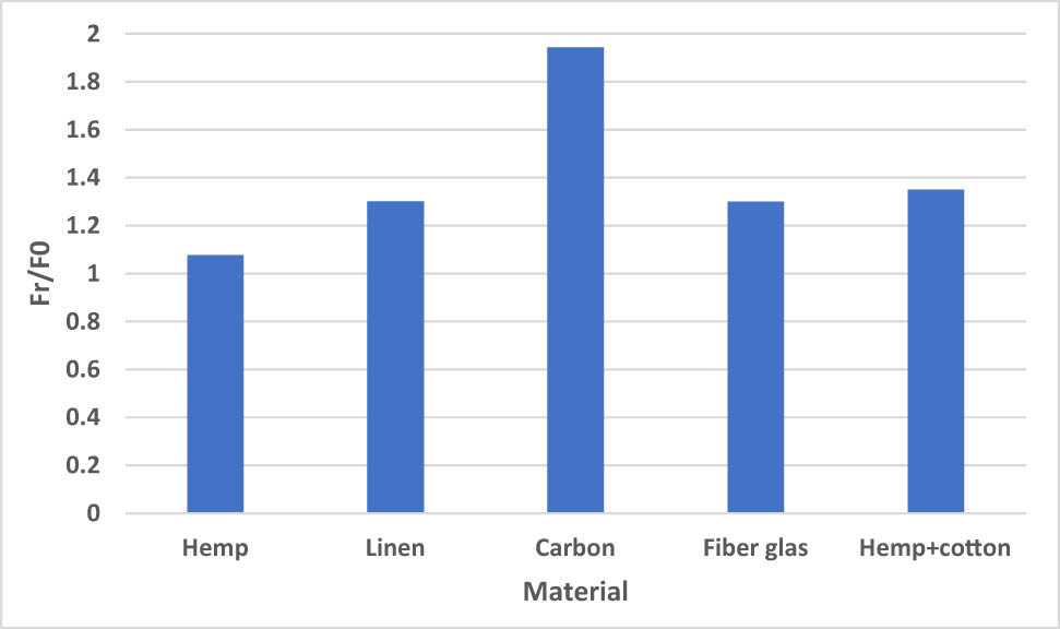
Influence of material type on ultimate load in the flexion test.
Figure 9 illustrates the bending behavior of the concrete specimens reinforced and instrumented by an LVDT displacement sensor. This result shows that the mixed linen and cotton materials provide remarkable resistance compared to the materials made with hemp or flax fibers alone.

Mechanical behavior of the strengthened concrete beams according to the different types of composite fiber fabrics using the LVDT sensor.
6 Conclusion
This paper presents another way of using natural fiber fabrics such as hemp, cotton, and linen for concrete strengthening. The advantages are numerous in terms of the environment, carbon impact, and their known physical, chemical, and thermal properties. However, this mechanical approach is novel in the reinforcement of concrete structures. This preliminary study provides interesting results on the strengthening of concrete and reinforced concrete beams using natural fiber composites. The results show an increase in the ultimate load from 5 to 35% compared to an unstrengthened concrete beam in flexural strength. The analytical study allowed us to describe the shearing and peeling stresses in the adhesive joint, plate, and concrete. The study shows a concentration of shear stresses at the ends of the adhesive joint. The same phenomenon is observed in concrete. However, the increase in shear strength changes the state of the stresses and gives rise to the development of peeling stresses. Thus, the allowable stress of the concrete will be reached, which will cause the collapse of the strengthened concrete beam bonded to the composite plate.
Acknowledgements
This research is fully supported and was financed by University Agency Francophonie, (Franch: Agence Universitaires de la Francophonie -AUF), Fund for Scientific Research (FSR) in Bulgaria through the Programs For Bilateral Cooperation 2018 - University Agency of Francophonie, within the framework of the project Study of biomaterials for strengthening reinforced concrete structures, BioRenfort, Ref. КП-06-фpaнкoфoния/4, which makes this important and effective research.
-
Conflict of interest: Authors state no conflict of interest.
References
[1] Raithby KD . External strengthening of concrete bridges with bonded steel plates. TRRL supp. Report 612. Crowthorne: Transport & Road Research Laboratory, Department of the Environment; 1980.Suche in Google Scholar
[2] Bresson J . Nouvelles recherches et application concernant l’utilisation des collages dans les structures – béton plaqué. France: Ann ITBTP; 1971 Feb. p. 278.Suche in Google Scholar
[3] Saadatmanesh H , Eshani M . Application of fiber-composites in civil engineering. Proceedings of the Sections Related to Structural Materials at Structures Congress. USA: ASCE; 1989.Suche in Google Scholar
[4] Ivanova I . Comportement mécanique de console courte en béton armé renforcée ou réparée par collage des matériaux composites [PhD thesis]. Reims: Université de Reims Champagne-Ardenne; 2013.Suche in Google Scholar
[5] Traintafillou T , Deskovic N . Innovative prestressing with FRP sheets: mechanics of short-term behavior. J Eng Mech. 1991;117(7):1652–72.10.1061/(ASCE)0733-9399(1991)117:7(1652)Suche in Google Scholar
[6] Tong FS , Chin SC , Doh SI , Gimbun J . Natural fiber composites as potential external strengthening material – a review. Indian J Sci Tech. 2017;10(2):1–5. 10.17485/ijst/2017/v10i2/110368.Suche in Google Scholar
[7] Benzarti K , Chlela R , Zombré W , Quiertant M , Curtil L . Durability of flax/bio-based epoxy composites intended for structural strengthening. MATEC Web of Conf. 2018;199:7014.10.1051/matecconf/201819907014Suche in Google Scholar
[8] Puranik PR , Vasavada DA , Patel VR . Use of woven fabrics for strengthening of reinforced concrete beams. Int J Eng Res Appl. 2014;4(3):52–8.Suche in Google Scholar
[9] Sangthongtong A . Strengthening of small concrete columns by natural fiber reinforced polymers composites (hemp FRP and sisal FRP) [Thesis for the Degree of Master of Science]. Pathum Thani: Sirindhorn International Institute of Technology Thammasat University; 2017.Suche in Google Scholar
[10] Assih J . Contribution à l’étude du renforcement et de la réparation de poutre en béton armé par collage de plaques composites en fibres de carbone [PhD thesis]. Reims: UFR Sciences de Reims; 1998.Suche in Google Scholar
[11] Kaiser H . Strengthening of reinforced concrete with epoxy bonded carbon fiber plastics [PhD thesis]. Zurich: ETH; 1986 (in German).Suche in Google Scholar
[12] Do Thi VV . Matériaux composites fibres naturelles/polymère biodégradables ou non [PhD thesis]. Grenoble: Université de Grenoble; 2011.Suche in Google Scholar
© 2021 Jules Assih and Ivelina Ivanova, published by De Gruyter
This work is licensed under the Creative Commons Attribution 4.0 International License.
Artikel in diesem Heft
- Effects of Material Constructions on Supersonic Flutter Characteristics for Composite Rectangular Plates Reinforced with Carbon Nano-structures
- Processing of Hollow Glass Microspheres (HGM) filled Epoxy Syntactic Foam Composites with improved Structural Characteristics
- Investigation on the anti-penetration performance of the steel/nylon sandwich plate
- Flexural bearing capacity and failure mechanism of CFRP-aluminum laminate beam with double-channel cross-section
- In-Plane Permeability Measurement of Biaxial Woven Fabrics by 2D-Radial Flow Method
- Regular Articles
- Real time defect detection during composite layup via Tactile Shape Sensing
- Mechanical and durability properties of GFRP bars exposed to aggressive solution environments
- Cushioning energy absorption of paper corrugation tubes with regular polygonal cross-section under axial static compression
- An investigation on the degradation behaviors of Mg wires/PLA composite for bone fixation implants: influence of wire content and load mode
- Compressive bearing capacity and failure mechanism of CFRP–aluminum laminate column with single-channel cross section
- Self-Fibers Compacting Concrete Properties Reinforced with Propylene Fibers
- Study on the fabrication of in-situ TiB2/Al composite by electroslag melting
- Characterization and Comparison Research on Composite of Alluvial Clayey Soil Modified with Fine Aggregates of Construction Waste and Fly Ash
- Axial and lateral stiffness of spherical self-balancing fiber reinforced rubber pipes under internal pressure
- Influence of technical parameters on the structure of annular axis braided preforms
- Nano titanium oxide for modifying water physical property and acid-resistance of alluvial soil in Yangtze River estuary
- Modified Halpin–Tsai equation for predicting interfacial effect in water diffusion process
- Experimental research on effect of opening configuration and reinforcement method on buckling and strength analyses of spar web made of composite material
- Photoluminescence characteristics and energy transfer phenomena in Ce3+-doped YVO4 single crystal
- Influence of fiber type on mechanical properties of lightweight cement-based composites
- Mechanical and fracture properties of steel fiber-reinforced geopolymer concrete
- Handcrafted digital light processing apparatus for additively manufacturing oral-prosthesis targeted nano-ceramic resin composites
- 3D printing path planning algorithm for thin walled and complex devices
- Material-removing machining wastes as a filler of a polymer concrete (industrial chips as a filler of a polymer concrete)
- The electrochemical performance and modification mechanism of the corrosion inhibitor on concrete
- Evaluation of the applicability of different viscoelasticity constitutive models in bamboo scrimber short-term tensile creep property research
- Experimental and microstructure analysis of the penetration resistance of composite structures
- Ultrasensitive analysis of SW-BNNT with an extra attached mass
- Active vibration suppression of wind turbine blades integrated with piezoelectric sensors
- Delamination properties and in situ damage monitoring of z-pinned carbon fiber/epoxy composites
- Analysis of the influence of asymmetric geological conditions on stability of high arch dam
- Measurement and simulation validation of numerical model parameters of fresh concrete
- Tuning the through-thickness orientation of 1D nanocarbons to enhance the electrical conductivity and ILSS of hierarchical CFRP composites
- Performance improvements of a short glass fiber-reinforced PA66 composite
- Investigation on the acoustic properties of structural gradient 316L stainless steel hollow spheres composites
- Experimental studies on the dynamic viscoelastic properties of basalt fiber-reinforced asphalt mixtures
- Hot deformation behavior of nano-Al2O3-dispersion-strengthened Cu20W composite
- Synthesize and characterization of conductive nano silver/graphene oxide composites
- Analysis and optimization of mechanical properties of recycled concrete based on aggregate characteristics
- Synthesis and characterization of polyurethane–polysiloxane block copolymers modified by α,ω-hydroxyalkyl polysiloxanes with methacrylate side chain
- Buckling analysis of thin-walled metal liner of cylindrical composite overwrapped pressure vessels with depressions after autofrettage processing
- Use of polypropylene fibres to increase the resistance of reinforcement to chloride corrosion in concretes
- Oblique penetration mechanism of hybrid composite laminates
- Comparative study between dry and wet properties of thermoplastic PA6/PP novel matrix-based carbon fibre composites
- Experimental study on the low-velocity impact failure mechanism of foam core sandwich panels with shape memory alloy hybrid face-sheets
- Preparation, optical properties, and thermal stability of polyvinyl butyral composite films containing core (lanthanum hexaboride)–shell (titanium dioxide)-structured nanoparticles
- Research on the size effect of roughness on rock uniaxial compressive strength and characteristic strength
- Research on the mechanical model of cord-reinforced air spring with winding formation
- Experimental study on the influence of mixing time on concrete performance under different mixing modes
- A continuum damage model for fatigue life prediction of 2.5D woven composites
- Investigation of the influence of recyclate content on Poisson number of composites
- A hard-core soft-shell model for vibration condition of fresh concrete based on low water-cement ratio concrete
- Retraction
- Thermal and mechanical characteristics of cement nanocomposites
- Influence of class F fly ash and silica nano-micro powder on water permeability and thermal properties of high performance cementitious composites
- Effects of fly ash and cement content on rheological, mechanical, and transport properties of high-performance self-compacting concrete
- Erratum
- Inverse analysis of concrete meso-constitutive model parameters considering aggregate size effect
- Special Issue: MDA 2020
- Comparison of the shear behavior in graphite-epoxy composites evaluated by means of biaxial test and off-axis tension test
- Photosynthetic textile biocomposites: Using laboratory testing and digital fabrication to develop flexible living building materials
- Study of gypsum composites with fine solid aggregates at elevated temperatures
- Optimization for drilling process of metal-composite aeronautical structures
- Engineering of composite materials made of epoxy resins modified with recycled fine aggregate
- Evaluation of carbon fiber reinforced polymer – CFRP – machining by applying industrial robots
- Experimental and analytical study of bio-based epoxy composite materials for strengthening reinforced concrete structures
- Environmental effects on mode II fracture toughness of unidirectional E-glass/vinyl ester laminated composites
- Special Issue: NCM4EA
- Effect and mechanism of different excitation modes on the activities of the recycled brick micropowder