Experimental study of the mechanical shear behaviour of steel rebar connectors in timber–concrete structure with leafy wood species
-
Ndjoya Rostand Mario
 and
Nkongho Anyi Joseph
and
Nkongho Anyi Joseph

Abstract
This study presents the experimental results of double shear tests obtained on timber–concrete connection systems. We evaluated the influence of factors such as the shape and diameter of the connector, grade of steel, and wood species on the mechanical shear performance of timber–concrete systems. The mechanical properties, such as the elastic shear strength, slip modulus, and failure mode of the tested specimens, are obtained from the load–slip curves of the push-out tests. The connectors tested are made from high-bond (HB) steels. The diameters used for the connectors are 10 and 12 mm and are of two shapes, straight and 90° head curved; steel grades are S400 and S500. The performance of the connectors has been tested on three species of wood, namely Iroko, Dabema, and Ayous. These solutions are chosen because they are simple to apply in a timber–concrete structure using materials available in the local market. We summarize the results of this work as follows: the systems of connection studies have the ability to respond to shear stresses; the failure mode of the connectors is ductile; and the timber species has an influence on the mechanical shear behaviour of the connectors.
1 Introduction
Constructions with timber–concrete structures are practical solution for new constructions and renovation of structures. Apart from the fact that it is considered a low-energy transformation resource, wood is an ecological and recyclable material. Its wide availability on Earth and its intrinsic physical properties make wood a competitive material for many applications in construction [1]. Timber–concrete technology constitutes a relevant alternative for using wood in construction, making it possible to save aggregate resources and optimize the mechanical properties of wooden structures [2]. Modern timber–concrete structures are inspired by the technology of mixed steel–concrete structures and are based on the background of timber–timber joints. It is since the Second World War that we have actually been discussing the construction with timber–concrete structures following a lack of steel; the idea of combining concrete with wood undoubtedly came from rehabilitation work requiring the preservation of historic existing structures [3,4]. The development of connection systems constitutes the key to the development of timber–concrete constructions (TCC). For example, the elements of timber concrete floors for buildings are composed of timber and a concrete slab, which allows each material to work in its field of preference which is tensile for timber, compression for concrete, and the connectors act in shear [5,6]. However, the effectiveness of mixed operation depends largely on the mechanical connection between the two materials; it is important to find an effective connection between the two materials in order to transfer forces without there being excessive deformation [7]. Different connection techniques between timber and concrete exist, but they constitute construction without normative rules. Their use requires specific studies in order to justify and validate their mechanical behaviour. The fundamental point of the design of a TCC is to ensure the reliability of the connectors in shear [8]. Therefore, from the viewpoint of mechanical performance, the ideal connection system must be strong enough to transmit the shear forces developed at the timber–concrete interface, sufficiently rigid to transmit the stress with limited slip to the timber–concrete interface, sufficiently ductile to allow full load distribution and avoid brittle failure of mechanism [9]. This means apart from the mechanical properties of concrete and timber, the structural response of such a composite system is heavily dependent on the shear strength, stiffness, and ductility performances of the used connection system. The elastic shear strength of the connection system is proportional to the maximum shear load transferred at the interface layer, while the stiffness is characterized by the slip modulus derived usually from the load–slip curve of experimental push-out tests. For a TCC floor, a high stiffness allows a reduction of the TCC thickness and controls the midspan deflection of the TCC floor due to an increase in bending stiffness of the TCC floor [10]. Some ductility is desirable since both timber and concrete behave relatively brittle in tension and compression, respectively, and the connection system is the only source of ductility for the TCC system [11]. The popularization of timber concrete constructions depends on the establishment of a specific standard for the verification of TCC. Several research projects related to the development of connection systems for TCC for the renovation and construction of buildings and bridges have been carried out over the last decade throughout the world.
The creep behaviour of mixed systems would be much more complex than for single-material concrete or wood structures. Connections with sufficient rigidity limit slip at the timber–concrete interface and help increase the mixed action [12]. Connectors can be classified into five families: rods connectors (studs, screws, nails, lag screws, bolts, etc.), continuous connectors, notches connectors, glues connections, and others (the combination of mentioned connectors) [13]. Ceccoti [7] classified the most commonly used shear connector into four categories according to their rigidity, ranging from the least rigid connections (pins, screws, dowels, high bond steel bars, etc.) to the most rigid connections (metal plates or steel mesh glued into wood). Different types of shear connection systems have been developed in the past, including steel rods, notches, and glue, in order to enhance the structural performance and cost-efficiency of TCC. Although they are generally considered the least rigid, rod connectors have the advantage of being inexpensive and easy to install. Gelfi and Giuriani [14] experimentally studied dowels obtained from ordinary steel rebars with diameters of 12 and 16 mm, inserted with a hammer into holes drilled in the timber. One of the objectives of the study was to evaluate the influence of the anchoring depth of the stud on the mechanical behaviour of the connection. They observed that an anchoring depth of the connector in the timber greater than 4 times the diameter of the connector did not have a great improvement in the strength and rigidity of the system. Dowel-type fasteners and metal continuous connectors can also be adopted along with the adhesive connection to withstand the brittle failure and uncertainty of adhesive behaviour in long-term performance. Piazza and Ballerini [15] tested glued-in dowel connectors and a continuous system made of steel sheet. Two types of glued-in dowel connectors were tested, including the bend dowel fastener, which was glued to the timber in one end while the other end was bent at 90° to connect with the concrete panel, and the concrete stocky connector, in which a straight dowel was adopted into the round notch connector. The results of full-scale bending tests on beams demonstrated that the composite beams exhibited linear responses up to nearly half the maximum load level, followed by a post-elastic hardening stage. Compared to the timber beam, using a glued-in bend dowel and concrete stocky could improve the bending strength approximately 2–2.5 times, as measured in the bending test. The long-term behaviour of timber concrete beams using the steel bars of diameter 18 mm inserted in the drilled holes of the timber beams and filled with epoxy adhesive was studied by Ceccotti et al. [16]. After five years of monitoring under constant load, bending tests were performed until failure. The results showed that the deflection increased significantly during the first two years of loading, with a slip observed at the ends of the beams that continued to progress after the testing period. A brittle failure in tension was observed in the timber part without significant plastic deformation in the connection. This showed that the stiffness of the connection was efficient, allowing the development of the composite action in the beams. Connectors made by curved steel bars with diameters of 8, 10, and 12.5 mm inserted into resinous timber species in the drilled holes of the timber and yield stress greater than 500 MPa were studied by Carvalho and Carrasco [17] to compare the two configurations of push-out specimens. The results showed an increase in shear resistance and stiffness with increasing connector diameter. A notch connector is an interlocking solution between concrete and timber, which is fabricated by cutting a groove in the top of the timber surface and filling it with concrete afterward; notches with rectangular and trapezoidal shapes are the most commonly adopted. To address the issue of brittle failure with notches connections, some authors study the reinforcement of additional fasteners or rod bars in the notch connection in order to improve the strength, ductility, and post-peak behaviour of the connection system. Gerber et al. [18] carried out 100 tests on the notch connections with lag screws. Many parameters were considered, such as the geometry of the notch, the direction of the lag screw (straight or inclined), and the mechanical properties of the concrete. The results showed that the inclined lag screw increases the strength of the connection in comparison with the straight one. However, the influence of the stiffness is less evident. Fragiacom and Lukaszewska [19] worked on the development of prefabricated timber–concrete floor systems by carrying out an experimental campaign of shear tests on small floor specimens and dynamic bending tests on full-size specimens; the results showed that prefabricated mixed timber–concrete structures perform satisfactorily under static and dynamic loads, and the best results were obtained by using a slotted connection reinforced with a screw, which was found to be much stiffer than the configuration of a lag screw only or steel plates nailed to the wood. Djoubissie et al. [13] have developed timber concrete connections using materials locally available in Sub-Saharan Africa. They focused on the mechanical behaviour of connectors based on high-bond steel (notably 2 families of connectors; the first consisting solely of threaded high-bond steel rods with diameters of 10 and 12 mm fixed in the timber by screwing and the second made of threaded high-bond steel rods of diameters 10 and 12 mm combined with triangular and rectangular notches in the timber on the areas around the connectors). The results showed that it is possible to achieve good mixed performance by using the connection with the combination of notch and threaded high-bond steel rods in timber concrete beams. With the facilitation of the Computer Numerical Control machine to manufacture the desired shape on the timber, various shapes of the notched connection, such as rectangle, round, dovetail, and trapezoid, have been studied. Ouch [20] studied the behaviour of the dovetail notched connector in cross-laminated timber (CLT) panel. A series of push-out tests was performed to determine the strength, stiffness, and ductility of the notched connector. The results showed that the shape of the notch is able to limit the separation between the concrete and CLT panels. Furthermore, the V-shape rebar cage inside the notch improves the uplift resistance and provides an additional dowel action to the concrete notch. It avoids the use of anchored steel screws or fasteners, thus facilitating onsite erection. Numerical models for predicting the mechanical behaviour of timber–concrete systems can be developed following the experimental results. The numerical model is based on the surrogate model, which is adequate for optimization simulation design with acceptable accuracy and reliability evaluation. The approach by Ma et al. [21] and Yang et al. [22] in their research work can be applied to the prediction of the mechanical behaviour of timber–concrete structures. Manufactured and patented connectors specially developed for timber–concrete systems exist, such as SBB connectors (these are metal lag screws with varying diameters of 20–25 mm for lengths of 150, 170, or 250 mm); Tecnaria connectors (these are connectors with lugs and studs); and SFS VB connectors (these are long screws that do not require pre-drilling the timber). The were studied by many researchers [23,24,25].
Experimental studies carried out so far by the authors on timber–concrete connection systems using high bond steel connectors do not analyse the influence of the 90° bend of the head of straight connector inserted perpendicularly to the grain of the timber as well as the influence of the leafy tropical wood species on the shear behaviour of high bond connectors. Most of the connectors studied require a high manufacturing time and do not simplify the construction process on site; therefore, they do not facilitate quality control. Moreover, manufactured connectors are only available in developed countries and remain expensive for the others. The present study is part of a dynamic of promoting the development of TCC using locally available wood species and connectors whose implementation does not require any particular skills. The aim is to obtain a technology of connection that is available and easy to use in the local context with adequate mechanical performances and reasonable costs. The local availability of different resources (timber, connectors, and concrete), the renewable nature of timber and the connector, and the time and constraints of implementation compared to most existing connection systems are assets for the development of local TCC.
An experimental campaign is carried out in the Laboratory of Mechanics and Materials of the National Higher Polytechnic School of Douala Cameroon with the aim of characterizing the mechanical shear performance of the timber–concrete system based on leafy tropical wood species and connectors made from HB steel bars used in the manufacture of reinforced concrete structures. The connectors are made of two shapes, straight and 90° head curved; the steel grades used are S400 and S500, and diameters are 10 and 12 mm. To avoid mechanical action of the thread, the connector, or the glue as it needs controlled conditions, sharpening is made at the extremity of the high bond connector to be sunk easily in the timber after a predrilling of timber (Figure 1). The mechanical shear characterization of HB connectors concerns the determination of elastic shear strength, the slip modulus, and the failure mode.
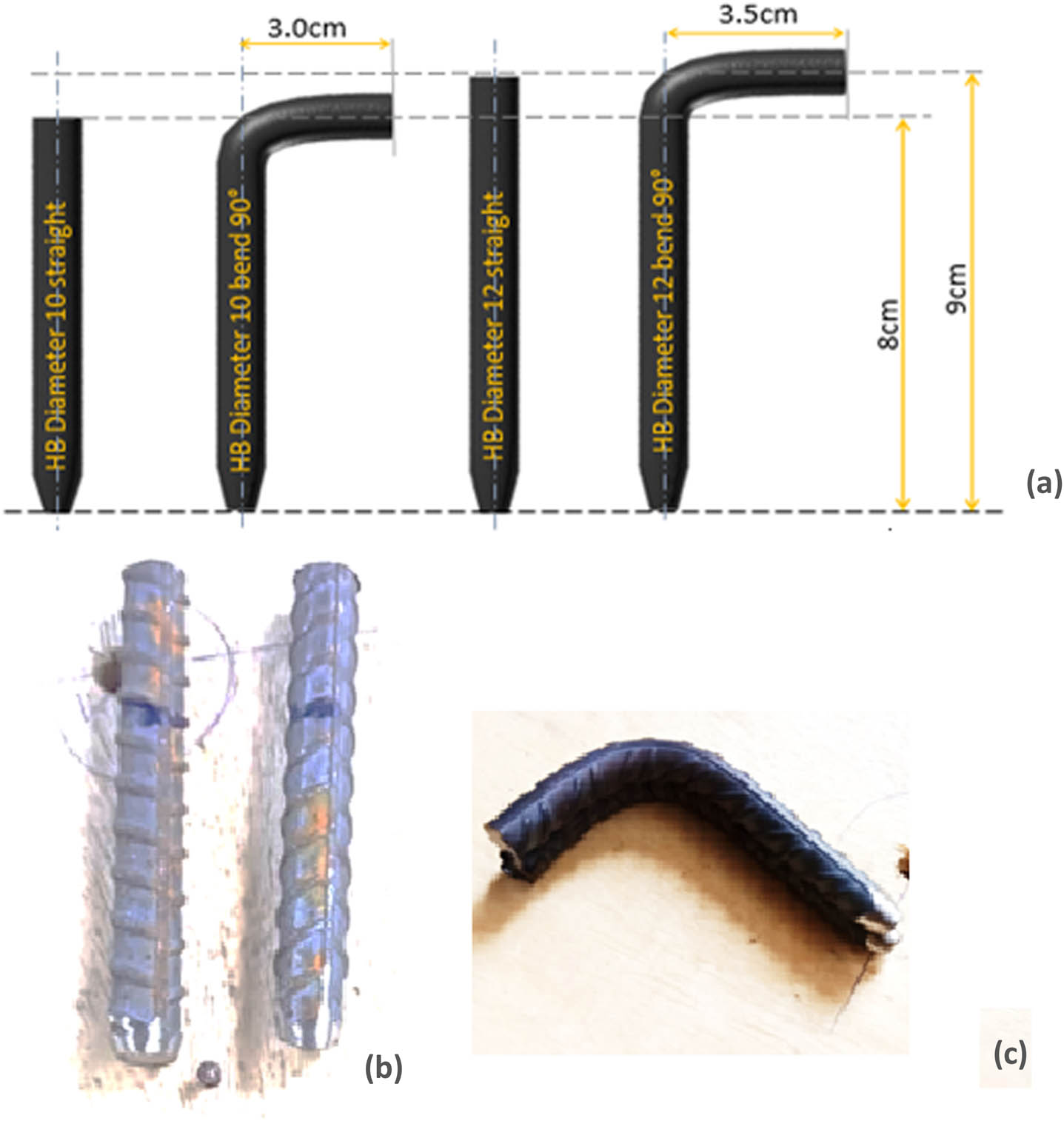
Illustration of the HB steel connectors shaped and tested: (a) shapes and dimensions of the connectors; (b) capture of straight HB connectors; and (c) capture of 90° head curved HB connectors.
The following list of tasks is pursued:
Acquisition and stocking of the different materials to be used in the experimental campaign. Wood samples acquired in the local Cameroonian market are machined and stored for drying on an above-ground wooden deck with natural ventilation for a period of 11 months (Figure 3), with a view to reaching the normative moisture content values on wood for tests [26].
Mechanical and physical characterization of different materials, wood species, steel and concrete to be used for shaped specimens for shear tests. After the evaluation of the physical characteristics of the various standardized wood, concrete, and steel samples, compression tests are carried out for wood and concrete, tensile tests for steel on a mechanical press, as well as 4-point bending tests for wood species with an electromechanical press.
Mechanical characterization of the different connectors after their shaping with double shear tests on an electromechanical press equipped with an acquisition unit and potentiometric sensors. Specimens for shear tests are composed of timber and a 5 cm-thick reinforced concrete slab (Figure 8).
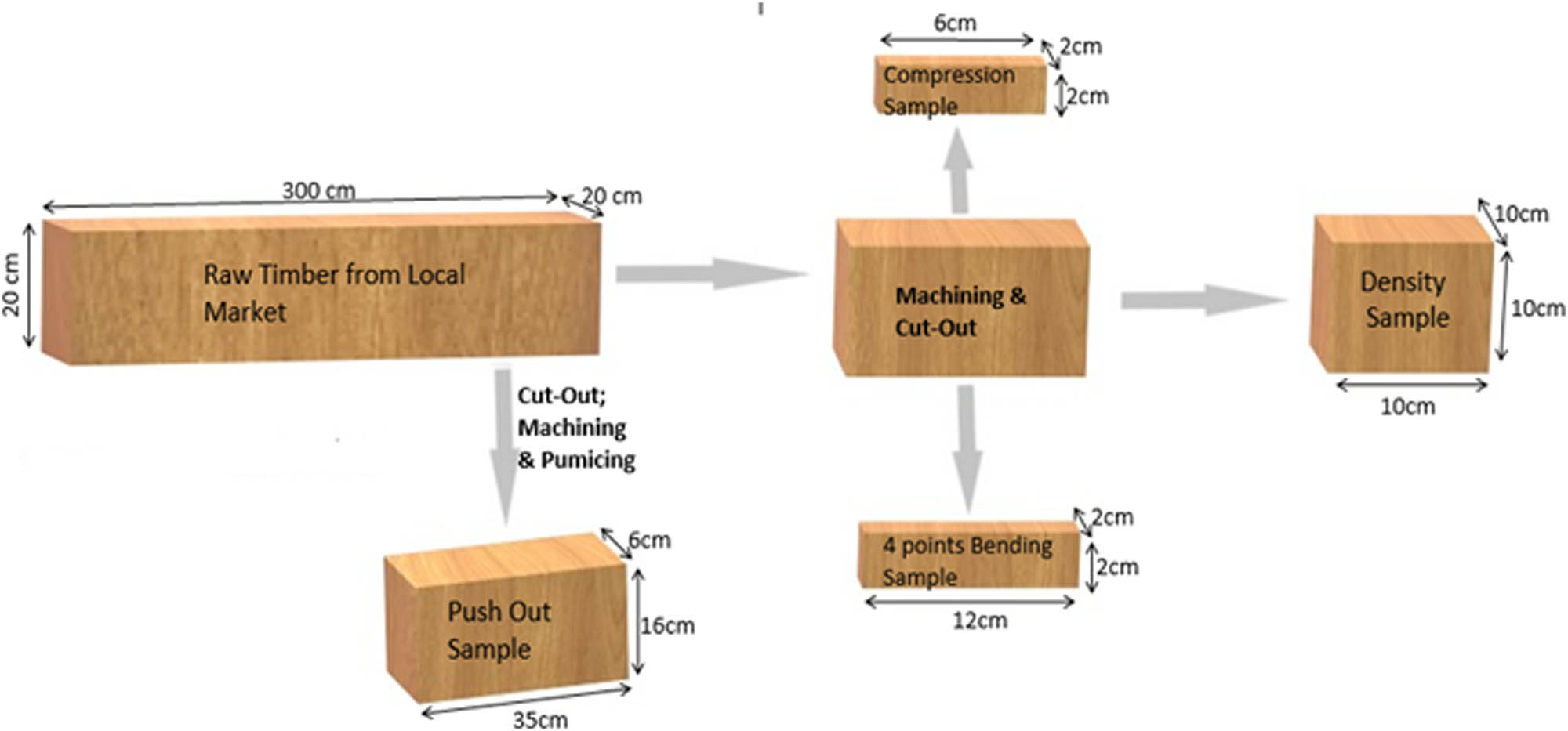
Cutting diagram of different wood samples.
2 Material characterization
2.1 Wood
As part of this work, the wood species used are two tropical leafy hardwoods, namely Iroko and Dabema, locally called Atui, and a leafy softwood Ayous [27]. The wood volumes come from three different wood deposits. They are sold in the form of wood lumber with average gross dimensions of 20 cm × 20 cm × 300 cm (Figure 2). Most of these woods come from traditionally harvested logs, without traceability of the origin of the trunks cut. The criteria for choosing species are their availability in the local market and the fact that their species are not subject to any particular restrictions. In addition to these two criteria, these woods have species called “promotional substitution species” [1].
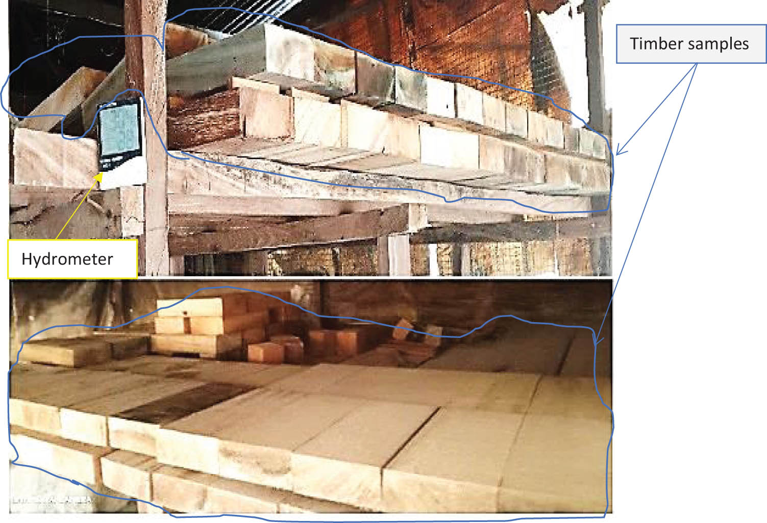
Traditional drying of wood samples.
A visual classification made it possible to classify our hardwood samples into the first category of structural timber, wood of good quality, excluding core and sapwood, and presents few defects. Three samples of each are taken from each plank after machining and cutting to determine the physical and mechanical characteristics, as well as samples for push-out tests.
The drying of the wood was carried out in an environment with relative humidity between 50 and 95% and at temperatures between 25 and 37°C (Figure 3). Monitoring woods moisture content (MC) until stabilization was carried out on samples showed that Ayous dries more quickly than Iroko and Dabema (8 months on average for the drying of Ayous samples, 10 months on average for drying of Iroko and 11 months on average for drying of Dabema).
Physical and mechanical properties of the wood are determined following the recommendations of standard NF EN 408 + A1 [28] (Figures 4 and 5). The samples used to determine the density (
![Figure 4
Determination of f
c,0 and E
m,g: (a) preparation of wooden test specimens (b) 4 points bending test on wooden specimens; (c) compression tests parallel to the grain on an electromechanical press and (d) requirements for the 4 points bending test (Standard EN408:1995 [29]).](/document/doi/10.1515/jmbm-2025-0037/asset/graphic/j_jmbm-2025-0037_fig_004.jpg)
Determination of f c,0 and E m,g: (a) preparation of wooden test specimens (b) 4 points bending test on wooden specimens; (c) compression tests parallel to the grain on an electromechanical press and (d) requirements for the 4 points bending test (Standard EN408:1995 [29]).
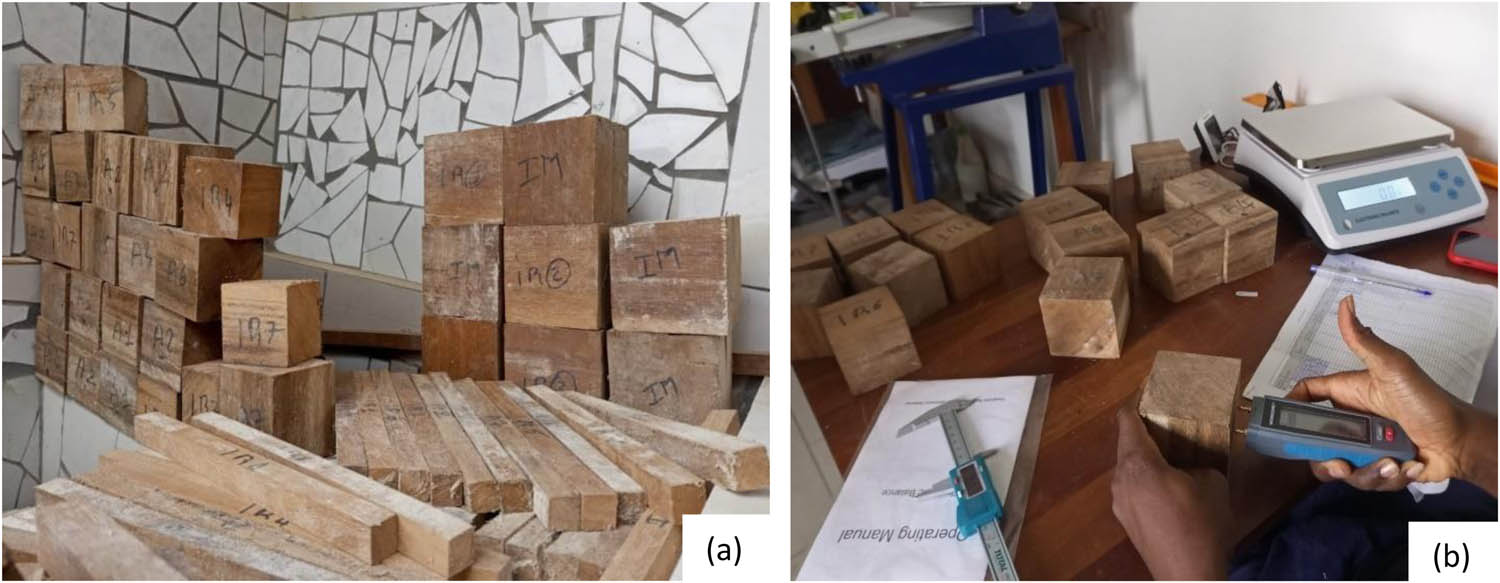
Determination of the physical properties of wood species: (a) cubic wood specimens for the determination of the density and (b) weighty for density and the moisture content evaluation of wood specimens.
The elasticity modulus of wood in bending (E m,g) is determined following the recommendations of Standard EN408:1995 [29]. The elasticity modulus is obtained with standardized wooden specimens without defects measuring 2 cm × 2 cm × 30 cm subjected to 4-point bending tests (Table 1).
Physical and mechanical properties of wood species tested
| Designation |
|
MC (%) |
|
E
m,g
|
|
|---|---|---|---|---|---|
| Ayous | Main value (CoV) | 392.0 (2%) | 12.2 (2%) | 26.6 (25.2%) | 6,998 (12.1%) |
| Dabema | 710.2 (6.2%) | 13.4 (4%) | 56.8 (15%) | 15,019 (15.2%) | |
| Iroko | 638.4 (8.1%) | 11.6 (3%) | 52.1 (17.3%) | 12,810 (14.5%) |
2.2 Steel
The connectors are made from high-bond steels for reinforced concrete steel bars commonly used in construction and available in the local market. As part of this study, two grades, S400 and S500, were used for the manufacture of the connectors, and for each grade, two diameters, namely 10 and 12 mm, were selected (Figure 6).
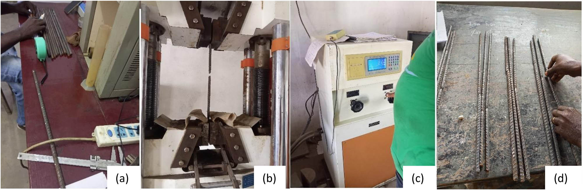
Characterization tests of HB steels for shaping connectors; (a) marking of samples before tensile tests; (b) & (c) steel fracture after tensile tests on a 1000t mechanical tensile and press data acquisition center; and (d) evaluation of the breakage of the bars after tensile tests.
The breakage load (f
r) and the elastic limit strength (f
yk) of the high bond steels used for the shaping of the different connectors were determined experimentally from tensile tests on specimens with 50 cm length for the grade S400 and 60 cm length for grade S500 following the protocol described by the standard EN 10002-1 [30]. The tests were carried out with a press loading speed in the range of 0.6–7 kN/s for specimens with a diameter of 12 mm and 0.5–6 kN/s for specimens with a diameter of 10 mm. The steel density (
Physical and mechanical properties of connector steel
| Designation | Steel grade |
|
f r (kN) | f yk (MPa) | |
|---|---|---|---|---|---|
| 10 mm | 12 mm | ||||
| Main value (CoV) | S400 | 7,297 (0.9%) | 60.5 (7%) | 75.8 (5%) | 424.7 (2%) |
| S500 | 62.4 (2%) | 80.2 (3%) | 484.6 (6%) | ||
2.3 Concrete
The compressive strength (f ck) and the density (ρ c) of the concrete were determined on the cubic samples measuring 10 cm × 10 cm × 10 cm (Figure 7). The strength class, as well as secant elasticity modulus in compression, are determined from the formulas proposed by the standard CEN NF EN 12390-13, 2014 (Tables 3 and 4) [31].
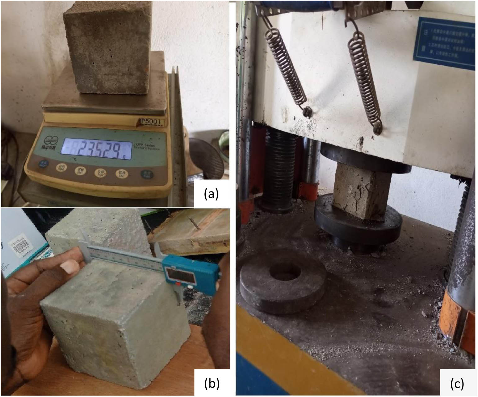
Physical and mechanical characterization of concrete; (a) weighty of cubic specimens on a precision scale; (b) reading the dimensions of the test specimens with digital caliper; and (c) compression test on cubic specimens.
Composition of the concrete used in the tests
| Sand 0/5 (kg) | Cement (kg) | Gravel 5/15 (kg) | Water (l) | Cement class |
|---|---|---|---|---|
| 432 | 400 | 1,140 | 186 | CEM II 42.5 R |
Experimental results of concrete characterization
| Designation |
|
f ck (MPa) | E cm (GPa) |
|---|---|---|---|
| Main value (CoV) | 2,321 (7.3%) | 23.05 (17%) | 28.26 |
The secant elasticity modulus of concrete is calculated from Eq. (1) [32]:
3 Push-out tests
3.1 Confection of push-out test specimens
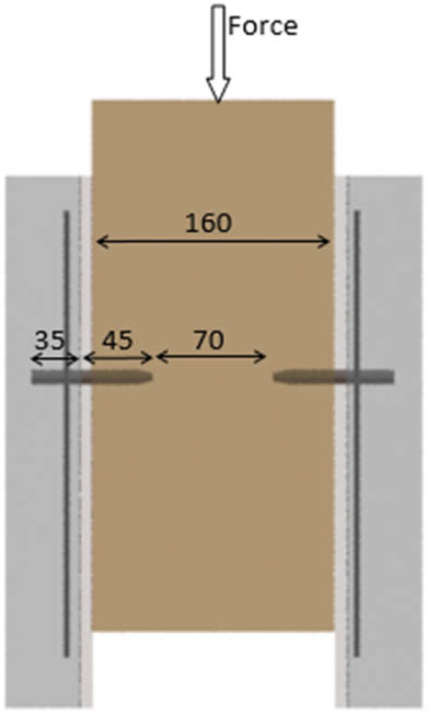
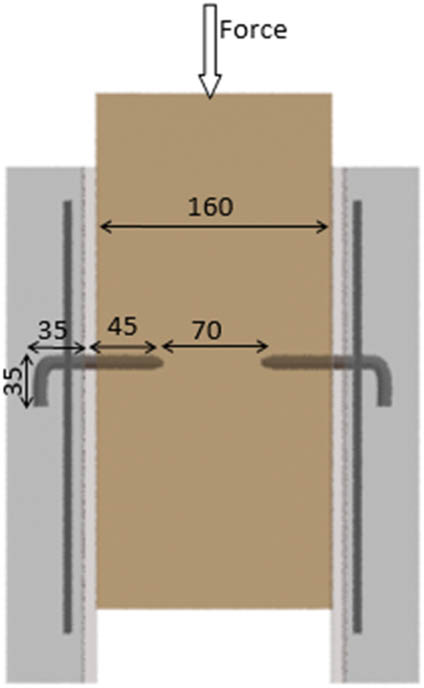
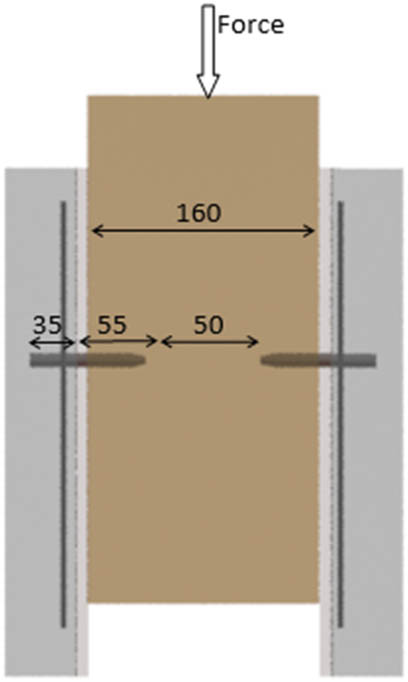
Specimens for double shear tests are characterized by a penetration depth (P) of the connectors, such as P ≥ 4d (where d is the diameter of the connector) [14]. In this study, we focused on the influence of factors such as the wood species (Iroko, Dabema, and Ayous), the grade of the steel connectors (S400 and S500), the diameter of the steel rod (10 and 12 mm), and the shape of the connectors (straight, 90° head bent) on the mechanical shear performance of connectors (Figure 1). A plywood of 10 mm thickness is used as formwork between the concrete slab and the timber (Figure 8). A total of 54 push-out specimens were shaped and tested. The notations adopted are shown in Table 5.

Principle of the specimen for the double shear test.
Codification of specimens for shear tests
| Codification | Description | Draft |
|---|---|---|
| HB10F4D | High bond (HB) steel connector with a straight shape and a diameter of 10 mm; steel grade is S400 (the timber pre-drilling diameter for inserting connector is 8 mm) |
 |
| HB10F4 | HB steel connector with 90° head bent with a diameter of 10 mm; steel grade is S400 (the timber pre-drilling diameter for inserting a connector is 8 mm) |
 |
| HB10F5 | HB steel connector with 90° head bent with a diameter of 10 mm; steel grade is S500 (the timber pre-drilling diameter for inserting a connector is 8 mm) |
 |
| HB12F4 | HB steel connector with 90° head bent with a diameter of 12 mm; steel grade is S400 (the timber pre-drilling diameter for inserting a connector is 10 mm) |
 |
| HB12F4D | HB steel connector with a straight shape and a diameter of 12 mm; steel grade is S400 (the timber pre-drilling diameter for inserting a connector is 10 mm) |
 |
| HB12F5 | HB steel connector with 90° head bent and a diameter of 12 mm; steel grade is S500 (the timber pre-drilling diameter for inserting a connector is 10 mm) |
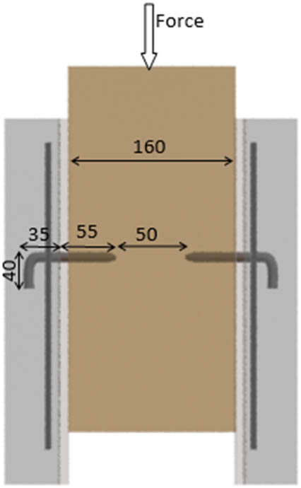 |
The connectors are fixed in the timber perpendicularly to the grain by using a 1 kg mass in pre-drilled holes made with a drill. The two forms of connectors (straight and 90° head curved) are studied mainly to evaluate the influence of the 90° curvature of the head of the straight connector on its mechanical behaviour in shear. The diameter of the pre-drilled hole is 1 mm less than the diameter of the connector to be inserted following a prescription from Eurocode 5 (CEN, 2004) [29].
After pouring the concrete, the specimens were kept in an environment where the temperature and relative humidity vary slightly, i.e. HR =
3.2 Mechanical characterization of connectors
In this work, the shear test protocol and the general principles for characterizing the performances of connectors are carried out according to Standard EN26891 [33]. Recently, the technical specification CEN/TS 19103 [34] has allowed to adoption of the loading procedure given by EN 26891 [33] in order to perform push-out tests for concrete–timber connections. Not having equipment allowing cyclical tests, all our symmetrical push-out tests are carried out at a constant speed of 3 kN/min on an electromechanical press equipped with a data acquisition unit. To monitor the relative slip between the timber and concrete during the shear test, two potentiometric sensors with a maximum shift of 25 mm are set symmetrically on the test pieces (Figure 9). The different test durations were between 10 and 15 min. All push-out tests are carried out after 28 days of concrete maturity (Figure 10).
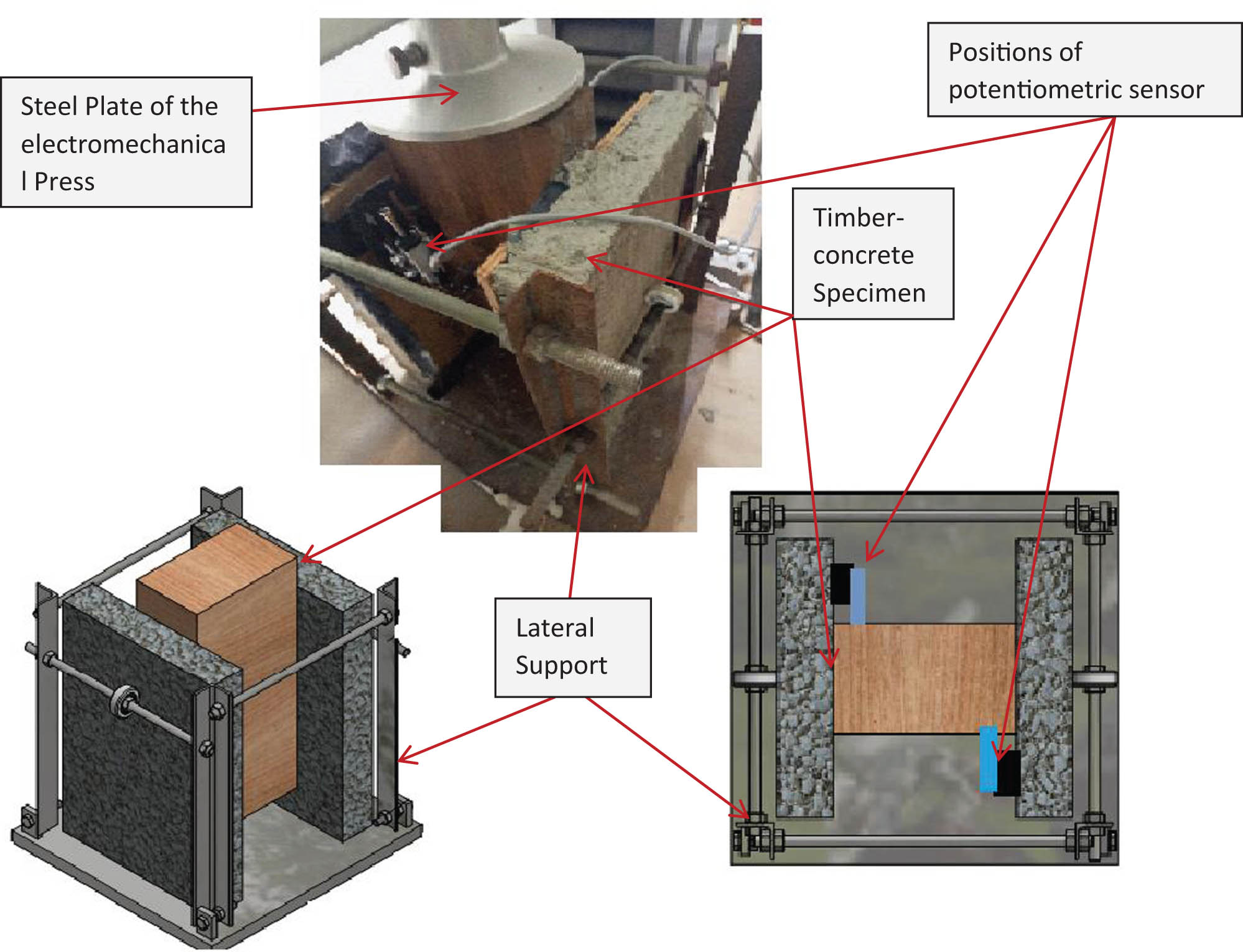
Testing setup and measurement system (push-out test).
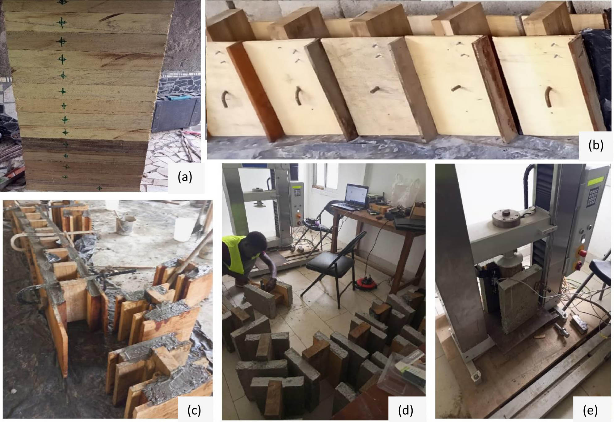
Specimens preparation for double push out tests: (a) marking and pre-drilling of timbers; (b) insertion of connectors in timbers; (c) formwork and concreting of specimens; (d) preparation of the specimens for Push Out tests, installation of potentiometric sensors; and (e) installation of specimens for push out tests on the electromechanical press.
The experimental characterization of the connector by symmetrical push-out tests concerns the theoretical evaluation of its in-service and ultimate sliding modulus (K s and K u) as well as its elastic shear strength and the failure mode following the protocol described in standard EN26891 [33]. The sliding modulus is calculated from the use of the load–slip curves obtained from the double shear tests. The shear test can be stopped when the ultimate load is reached or for a slip value of 15 mm. The load reached before or at the slip of 15 mm is considered to be F max. At each test, the use of the load–slip curves makes it possible to determine the following:
The maximum load reached F max during the shear test, as well as the corresponding average slip obtained using the potentiometric sensors
0.1F max and V 01 correspond, respectively, to 10%F max and the initial slip at 10% of the maximum load F max
0.4F max and V 04 correspond, respectively, to 40% of the maximum load F max and the initial slip at 40% of the maximum load F max
The modified slip and the subsidence of the assembly are calculated, respectively, by the following equations:
(2)(3)The in-service and ultimate sliding modulus are calculated, respectively, by
The experimental determination of the elastic shear strength of the connector, which we denote Re (in kN), is carried out using the European Committee for Standardization Method cited and used in 2008 by Muñoz et al., in their work [35]. The elastic shear strength is defined as the intersection between the initial slip slope and a tangent to the experimental load–slip curve. The initial slip slope is defined as the slope between the value at 10 and 40% of the ultimate load. This slope forms an angle α relative to the horizontal. The tangent point is defined as the point on the experimental curve where the angle β of the tangent slope K β corresponds to one-sixth of the angle α, as presented in Figure 11. The elastic shear strength is the point corresponding to the intersection between the two slopes.
![Figure 11
Diagram for determination of elastic shear strength of the connector; use of the CEN method for determination of Re (Muñoz et al [35]).](/document/doi/10.1515/jmbm-2025-0037/asset/graphic/j_jmbm-2025-0037_fig_011.jpg)
Diagram for determination of elastic shear strength of the connector; use of the CEN method for determination of Re (Muñoz et al [35]).
Concerning the failure mode of the connection for the push-out specimens, two natures can be observed: ductile or brittle. To quantify the failure mode, a ductility parameter ∇ is proposed and defined as the ratio of the difference between the maximum load F max and the load at 15 mm of the slip divided by the maximum load F max. The failure mode is considered ductile when the parameter ∇ is lower than 20%. This means the connection can reach a slip of 15 mm with a decrease of maximum load F max lower than 20%. All the other failure modes are considered brittle or quasi-brittle. This definition of the ductility is based on the fact that the standard EN 26891 [33] recommends stopping the push-out tests on the connections when a slip of 15 mm is reached and also on the fact that the slip on the timber–concrete composite beams used is less than 15 mm. A decrease of maximum load F max higher than 20% is considered as brittle if it arises with a slip lower than 15 mm, as it can create a brittle failure in the timber–concrete structure [36].
4 Results and discussion
The load–slip curves from the different tests are grouped by the type of connector tested (straight and 90° head curved) in Figure 12. Most of the tests were conducted beyond 15 mm of slip, except those for which the failure occurred before.
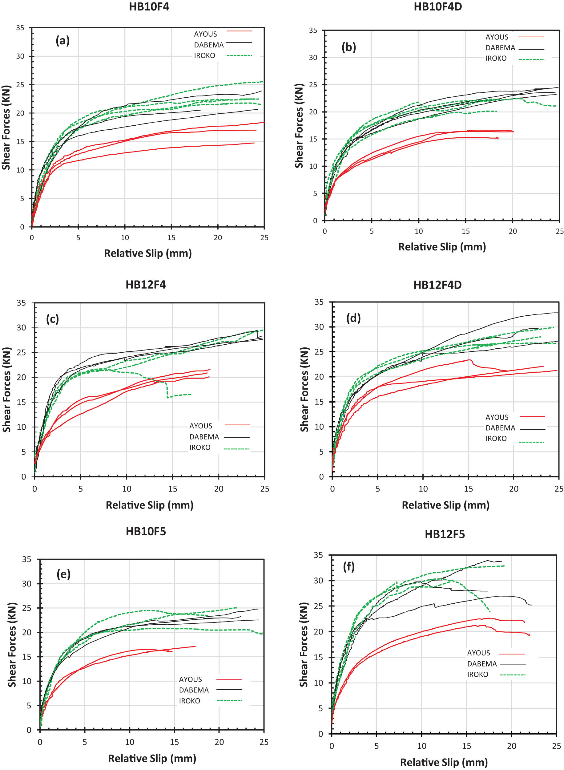
Load – Slip curves from double shear tests.
The load–slip curves obtained for the different combinations present two phases (the pseudo-elastic phase and a plastic phase).
Eqs. (2)–(5) are used to determine the shear parameters of the connectors. The slip value for each curve represents the mean value of the two potentiometric sensors. The average values of the mechanical characteristics of the tested connectors are presented in Table 6. They are the load values considering the maximum load (F max) reached before or at a slip of 15 mm; values of slips V i , V i,mod, and V s; the elastic strength for one connector Re for all tested; the initial stiffness, the stiffness at the SLS (serviceability limit state) and the ULS (ultimate limit state) (K i , K s, K u). The coefficients of variation of the parameters are also given in Table 7 to give an idea about the variability. All the connections tested show a coefficient of variation of the maximum load and slip modulus, respectively, around 7 and 5%; it is considered acceptable for the timber structure tests [18]. However, the majority of the available studies on the timber–concrete connections explain the variations of the test results by various parameters such as the method of preparation, the variability of the materials, and the nature of the connections [37].
Mains values of the mechanical characteristics of the connectors tested in shear
| Connection | Timber (number of samples) | Value | F max (N) | Average slip at F max (mm) | V i = V04 (mm) | V i,mod (mm) | V s (mm) | K i (kN/mm) | K s (kN/mm) | K u (kN/mm) | Re (N) |
|---|---|---|---|---|---|---|---|---|---|---|---|
| HB10F4 | Iroko (4) | MEAN (CoV) | 20876.80 (13.74%) | 14.99 (0.08%) | 1.25 (16.7%) | 1.51 (14.5%) | −0.28 (7.07%) | 6.71 (6.85%) | 2,768 (7.05%) | 1.85 (7.05%) | 4958.25 (13.7%) |
| Dabema (3) | 20548.84 (5.64%) | 14.96 (0.24%) | 1.12 (9.6%) | 1.45 (8.7%) | −0.32 (12.6%) | 7.32 (7.24%) | 2.84 (6.7%) | 1.89 (6.7%) | 4880.35 (5.64%) | ||
| Ayous (3) | 15772.47 (8.35%) | 14.99 (0.1%) | 1.14 (6.13%) | 1.36 (7.95%) | −0.22 (27.83%) | 5.54 (7.35%) | 2.32 (2.4%) | 1.55 (2.4%) | 3745.96 (8.35%) | ||
| HB10F4D | Iroko (3) | Mean (CoV) | 21305.00 (4.42%) | 13.78 (16.14%) | 1.17 (12.92%) | 1.51 (10.2%) | −0.33 (9.2%) | 7.34 (10.7%) | 2.84 (8.12%) | 1.89 (8.12%) | 5059.94 (4.42%) |
| Dabema (4) | 22256.42 (2.25%) | 14.95 (0.26%) | 1.12 (7.83%) | 1.47 (4.9%) | −0.35 (17.2%) | 7.96 (5.46%) | 3.03 (3.2%) | 2.02 (3.2%) | 5285.90 (2.25%) | ||
| Ayous (3) | 15997.06 (3.26%) | 14.99 (0.0%) | 1.03 (4.13%) | 1.35 (3.35%) | −0.32 (11.1%) | 6.19 (3.26%) | 2.36 (2.04%) | 1.58 (2.04%) | 3799.30 (3.26%) | ||
| HB10F5 | Iroko (3) | Mean (CoV) | 22730.60 (6.17%) | 14.97 (0.0%) | 1.12 (6.%) | 1.33 (4.%) | −0.21 (14.4%) | 8.13 (10%) | 3.39 (3%) | 2.26 (3%) | 5398.52 (6.%) |
| Dabema (3) | 22107.82 (1.54%) | 14.92 (0.8%) | 1.10 (4.%) | 1.39 (7.5%) | −0.29 (18.5%) | 8.05 (2.85%) | 3.20 (6.55%) | 2.14 (6.55%) | 5250.61 (1.54%) | ||
| Ayous (2) | 16353.48 (1.89%) | 14.85 (0.1%) | 1.00 (2.5%) | 1.29 (1.72%) | −0.29 (7.2%) | 6.56 (1.45%) | 2.54 (1.76%) | 1.70 (1.76%) | 3883.95 (1.89%) | ||
| HB12F4 | Iroko (3) | Mean (CoV) | 23744.00 (6.03%) | 12.38 (27.71%) | 0.92 (8.83%) | 1.16 (4.55%) | −0.24 (18.3%) | 10.41 (4.67%) | 4.10 (2.7%) | 2.73 (2.7%) | 5729.70 (3.7%) |
| Dabema (3) | 25909.13 (0.63%) | 14.95 (0.24%) | 1.05 (8.24%) | 1.28 (2.06%) | −0.23 (18.63%) | 9.90 (7.33%) | 4.04 (1.75%) | 2.69 (1.75%) | 6153.42 (0.6%) | ||
| Ayous (3) | 19785.66 (2.26%) | 14.85 (2.8%) | 1.01 (4.58%) | 1.35 (4.33%) | −0.34 (4.1%) | 7.81 (2.36%) | 2.93 (2.06%) | 1.95 (2.06%) | 4699.10 (2.26%) | ||
| HB12F4D | Iroko (3) | Mean (CoV) | 26479.40 (2.54%) | 15.0 (0.0%) | 1.06 (4.5%) | 1.35 (7.5%) | −0.29 (14.6%) | 9.94 (10.7%) | 3.91 (6.5%) | 2.60 (6.5%) | 6288.85 (2.54%) |
| Dabema (3) | 27034.58 (5.03%) | 14.95 (0.36%) | 1.03 (6.23%) | 1.35 (4.7%) | −0.32 (6.27%) | 10.52 (5.11%) | 4.0 (3.04%) | 2.67 (3.04%) | 6420.71 (5.03%) | ||
| Ayous (3) | 20731.09 (5.33%) | 13.93 (8.61%) | 1.03 (4.27%) | 1.36 (3.8%) | −0.33 (4.61%) | 8.06 (1.5%) | 3.04 (2.2%) | 2.03 (2.2%) | 4923.63 (5.33%) | ||
| HB12F5 | Iroko (3) | Mean (CoV) | 31196.50 (2.94%) | 14.06 (9.32%) | 1.16 (10.54%) | 1.54 (10.54%) | −0.39 (10.54%) | 10.85 (7.2%) | 4.07 (7.2%) | 2.71 (7.2%) | 7409.17 (2.94%) |
| Dabema (3) | 29425.80 (9.18%) | 13.08 (20.12%) | 1.09 (15.4%) | 1.41 (16.6%) | −0.32 (27.63%) | 10.85 (14.4%) | 4.18 (7.7%) | 2.79 (7.7%) | 6988.63 (9.18%) | ||
| Ayous (2) | 21511.14 (2.58%) | 14.95 (0.06%) | 1.07 (2.05%) | 1.39 (1.2%) | −0.33 (4.1%) | 8.07 (1.5%) | 3.10 (1.9%) | 2.07 (1.9%) | 5108.90 (2.58%) |
Ductility ∇ of connectors tested in shear
| Wood species | Values ∇ [%] | HB10F4 | HB10F4D | HB12F4 | HB12F4D | HB10F5 | HB12F5 |
|---|---|---|---|---|---|---|---|
| AYOUS | Main (CoV) | 5.4 (8.3%) | 2.1 (3.3%) | 5.8 (2.3%) | 7.2 (5.3%) | 1.5 (2.0%) | 2.2 (2.5%) |
| DABEMA | 5.6 (5.64%) | 4.6 (2.3%) | 8.6 (1.0%) | 8.9 (5.0%) | 7.9 (1.5%) | 3.0 (9.2%) | |
| IROKO | 11.2 (13.7%) | 1.7 (4.4%) | 10.1 (2.5%) | 4.3 (2.5%) | 4.0 (6.2%) | 1.0 (2.9%) |
4.1 Influence of the wood species on the mechanical behavior of connectors
The shear mechanical behaviour of various connectors showed an obvious nonlinear performance for all series. The load–slip curves of all connections, irrespective of the wood species, clearly show two phases (Figure 12): one phase of the load increases in a pseudo-elastic way with a slip of less than 5 mm, and the second phase of the load increases slowly to reach an asymptote before failure of the connection system with an average slip of 14 mm; this phase can be associated to the plastic deformation of the HB connector.
Broadly speaking, all the connectors tested show better mechanical performance in terms of elastic shear strength and slip modulus in Dabema wood species than in Ayous and Iroko species (Figure 13); it was observed that with Ayous, the mechanical performances in terms of slip modulus in service and elastic shear strength are less high compared to those obtained with Iroko and Dabema species. The density of each species tends to justify this gap. For the Dabema wood species, its density is better than that of Iroko and Ayous species, with a difference of 10 and 45%, respectively; for the Iroko wood species, its density is higher than that of Ayous wood species, with a relative gap of 38%. The elastic strength of the connectors in the Dabema wood species is higher compared to those in the Iroko and Ayous wood species, with respective differences of 4 and 24%. The shear modulus of connectors in Dabema wood species is higher than 2% compared to that in Iroko and 15% compared to that in Ayous. The elastic shear strength and the slip modulus of the connectors in the Iroko wood species are higher than in the Ayous wood species, with respective differences of 23 and 14%.
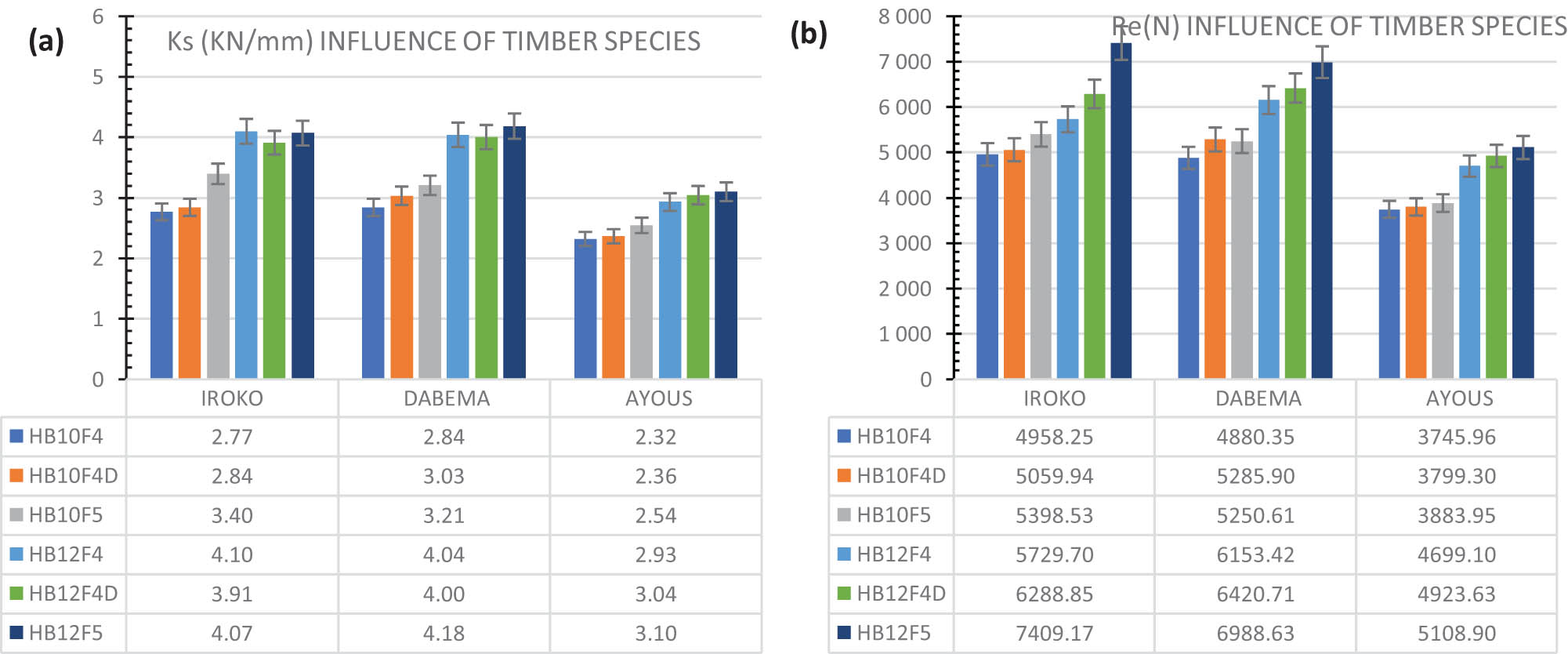
Influence of the timber species on the mechanical behavior of the connectors: (a) influence of timber species on Ks and (b) influence of timber species on Re.
4.2 Influence of the connector type (shape, diameter, and steel grade of the connector)
The load–slip curves of the HB10F5 and HB12F5 connectors (Figure 12(e) and (f)) show an increase in the maximum load for the three wood species when the connector diameter increases from 10 to 12 mm; the average maximum load for connectors in the Ayous wood species shows an increase of 5.2 kN, this increase in the Dabema species is 7.3 and 8.4 kN in the Iroko species. It is noted that the increase is not constant but remains between 5 and 10 kN for the three wood species; this could be partly explained by the intra-specific (inter-individual) variability character that wood has.
Overall, straight connectors HB10F4D and HB12F4D (Figure 12(c) and (d)) tend to have better shear mechanical performance in terms of elastic shear strength compared to 90° head curved connectors (HB10F4, HB10F5, HB12F4, andHB12F5); the relative difference of the elastic shear strength Re between straight connectors compared to 90° head curved connectors are, respectively, 2.9, 5.9, and 5.4% in Ayous, Dabema, and Iroko wood species. The sliding modulus is a little higher for 90° head curved connectors compared to that obtained with straight connectors; the relative difference of the sliding modulus K s between 90° head curved connectors compared to straight connectors are, respectively, 8.2, 2.7, and 1.4% in Ayous, Dabema, and Iroko wood species. However, we note that these differences between the values of K s and Re of the straight connectors and 90° head curved connectors are not significant enough.
For the two shapes of connectors tested (straight and 90° head curved), the steel grade has an influence on the sliding modulus K s and the elastic shear strength Re of the connectors. An overall increase of approximately 5.5% of sliding modulus K s and 11.2% for elastic shear strength Re was observed for connectors of resistance class S500 compared to connectors of grade S400.
Irrespective of the shape of the connector and its steel grade, the diameter of the connector has an influence on its mechanical performance in shear in terms of sliding modulus and elastic strength in shear. An almost constant increase was observed for the values of K s and Re in the three wood species for the connectors of diameter 12 mm compared to those of diameter 10 mm. The relative gap between K s and Re for the connectors of diameter 12 mm compared to the connectors of diameter 10 mm in the wood species Dabema are, respectively, 24.7 and 20.0%; in the Iroko wood species, these differences are, respectively, 25.4 and 20.7%; in the Ayous wood species, the differences are, respectively, 24.0 and 20.6%.
4.3 Failure mode
The failure mode of all connectors tested is ductile (Table 7); the main parameter of ductility ∇ is equal to 8.4, 3.0, 9.2, 7.0, 4.5, 2.0%, respectively, for the HB10F4, HB10F4D, HB12F4, HB12F4D, HB10F5, and HB12F5 connectors.
The failure connection system is followed for all the tested specimens. More precisely, the timber–connector connections and the concrete–connector connections.
Concerning the failure of the concrete–connector connections, concrete tearing on a few specimens with straight connectors was observed in the plastic deformation phase of the connector (6 tested specimens concerned). This difference in behaviour could be explained by the shorter anchoring length of the straight connector in the concrete than the 90° head curved connectors. The 90° head curved connectors, because of their shape, have greater anchorage in concrete, thus presenting a greater range of embedment than straight connectors. After a high level of loading, concrete cracks at the surface of the concrete slab in the direction parallel and perpendicular to that of the grain timber beam were often observed on the specimens with both connector shapes (straight and 90° head curved) during the tests (5 tested specimens affected by the 90° head curved connectors and 2 tested specimens concerned by the straight connectors) (Figure 14). Concrete cracks are more observed on specimens with the connector embedded in the concrete close to 1 cm; they generally originate around the connector anchor after the concrete has burst by the connector.
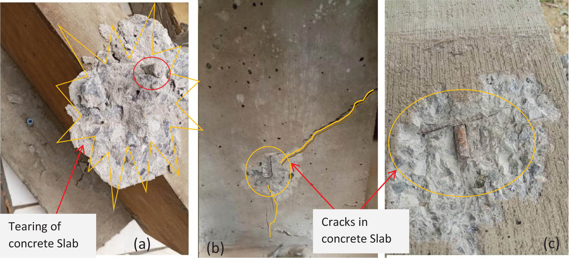
Failure of the concrete-connector: (a) tearing of the concrete by a straight connector; (b) and (c) cracks in the concrete by 90° head curved connectors.
Concerning the breakage of timber connector connections, it is characterized by internal damage to the timber-producing fiber extrusions caused by sliding stratification of the connectors (Figure 15), more pronounced on the Ayous wood species and for the connector with a diameter of 12 mm.
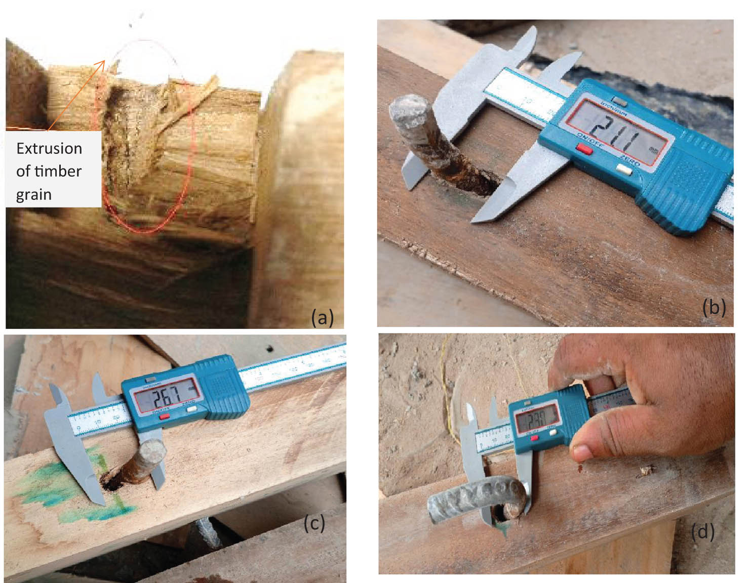
Failure of the timber-connector: (a) extrusion of timber grain by the connector; (b) embedment of straight connector on Dabema timber specie; (c) embedment of straight connector on Ayous timber specie; and (d) embedment of 90° head curved connector on Dabema timber specie.
Straight and 90° head curved connectors are deformed by presenting plastic hinges (Figure 16). No connector breakage was observed after the tests. The development of these plastic hinges seems to be proportional to the density of the wood species, the grade of the steel, and the diameter of the connector. It was observed that when the plastic deformation of the connector is less pronounced at the end of the test, the failure of the wood by extrusion of the grains at the level of the connector anchorage is more amplified. The development of plastic deformation of the connectors is less pronounced on connectors with a diameter of 12 mm, grade S500 in the Ayous wood species compared to the two hardwood species with the same diameter and grade steel; certainly because of the foundation modulus of the connector which is reduced in the softwood Ayous species compared to the Iroko and Dabema hardwood species [38].
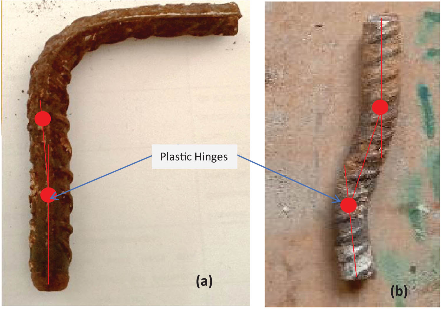
Plastic deformations of the connectors after tests: (a) example of plastic deformation of 90° head curved connector and (b) example of plastic deformation of straight connector.
4.4 Theoretical evaluation of shear capacity
Since no standard method has yet been established for evaluating the mechanical properties of connectors for timber–concrete systems, the theoretical evaluation approach for steel rod assemblies for timber–concrete structures often used by authors [39] is the one proposed on Eurocode 5 (EC5) [29] for timber–timber steel connections. EC5 [29] formulas very often tend to overestimate the mechanical values of the connectors compared to the values obtained experimentally. The theoretical value of the sliding modulus (notation K ser in EC5 [29]) is based on the connector type, timber density, and connector diameter. The equations are as follows:
Screw
Non-pre-drilled nail
where ρ m is the density of the timber element (kg/m3), and d is the outer diameter of the connector (mm).
Based on the values in Table 8, EC5 [29] tends to overestimate the in-service sliding modulus of the connectors tested with an average difference of 54.9% between the calculated values and experimental values for the timber species used in the tests. Furthermore, Djoubissie et al. [13] experimentally evaluated the sliding modulus of a high bond connector of grade S400 inserted into a tropical hardwood species Kosipo by screw. Although the fixing conditions are slightly different (our connectors, for example, are inserted into the wood by hammering, and those of Djoubissie by screw). It is a question of assessing the difference between the sliding modulus of HB connectors in shear of the same shape for the two experimental studies. The average differences in sliding modulus between HB connectors for steel grade S400 and 90° head curved threaded shape and tested by Djoubissie et al. [13] in the Kosipo wood species and our connectors with the same mechanical characteristics for the three wood species are around 24.5% for a 10 mm diameter and 21.4% for a 12 mm diameter. Our tested connectors tend to give a higher sliding modulus compared to those tested by Djoubissie.
Comparison of test results with theoretical results of EC5 [29] and experimental results of Djoubissie et al. [13]
| Connection | Experimental K s (kN/mm) | K ser according to EC5 (kN/mm) | Djoubissie K sd (kN/mm) | ΔK s/K ser | ΔK s/K sd |
|---|---|---|---|---|---|
| HB10F4 | 2.65 | 6.55 | 2 | 59.5% | 24.5% |
| HB10F4D | 2.74 | 6.55 | N.U(*) | 58.1% | N.U(*) |
| HB10F5 | 3.05 | 6.55 | 53.4% | ||
| HB12F4 | 3.69 | 7.86 | 2.9 | 53.0% | 21.4% |
| HB12F4D | 3.65 | 7.86 | N.U(*) | 53.5% | N.U(*) |
| HB12F5 | 3.78 | 7.86 | 51.9% |
5 Conclusion
In this study, experiments were performed in the Laboratory of Mechanic and Materials of the National Higher Polytechnic School of Douala Cameroon to analyse the behaviour of the timber–concrete connections using tropical leafy species from Africa and on high-bond steel connectors for reinforced concrete. The first step of the work consisted of the acquisition of the different materials to be used in the experimental campaign in the local market of Douala, Cameroon, and their storage. The second step consisted of the physical and mechanical characterization tests of the different materials on standardized wood, concrete, and steel specimens. The third phase consisted of shaping connectors, symmetrical push-out test specimens composed of timber and a 5 cm thick reinforced concrete slab, and then double shear tests to obtain the main mechanical parameters of connectors.
The main results showed the following:
Straight and 90° head curved steel connectors introduced into different species of tropical leafy wood by hammering prove their ability to respond to shearing stresses. The mechanical shear behaviour of different connectors showed a clear nonlinear performance for all series and a ductile failure mode. The load–slip curves of all connections, irrespective of the wood species, show clearly two phases: the load increases pseudo-elastically with a slip less than 5 mm in the first phase; in the second phase, the load increases slowly, characterizing a plastic deformation of the connection system.
Bending the connector at 90° compared to keeping it straight reduces the risk of breaking the connection system by tearing out the concrete. Inserting the 90° head curved connector into wood by hammering is less obvious than the straight connector. The mechanical shear performances of the two connector shapes are quite similar.
Dabema and Iroko hardwoods improve the mechanical performance of connectors in shear compared to Ayous softwood; an improvement in the values of elastic shear strength and sliding modulus of the connector of the order of 25 and 15%, respectively, is obtained when the connector is used in Dabema wood than in Ayous wood species.
The mechanical performance of HB connectors in shear improves, on the one hand, with its diameter, on the other hand, with its grade class. An average increase of 5.5% in the connector’s sliding modulus is observed for grade S500 compared to grade S400; similarly, an average increase of 24% in K s and 20% in Re is also observed when the connector of diameter 12 mm is used compared to the connector diameter of 10 mm for the three wood species tested.
These results make it possible to validate the mechanical performance of tropical leafy wood in responding to shear stresses when used in timber–concrete composites.
In this work, some aspects are not approached, in particular, the following:
The influence of the variation in time of mechanical properties, including creep, shrinkage, and moisture content of timber and concrete, on the structural behaviour of timber–concrete HB connectors in shear.
The influence of the insertion of the plywood at the timber–concrete interface on the mechanical behaviour of the HB connectors put in on tropical leafy species.
The influence of an inclination of the straight HB connectors of an angle less than 90° relative to the wood grain on the mechanical shear behaviour of the straight connector.
An application using the method γ given in annex B of Eurocode 5 [27] can be performed to compare the tested connection systems considered in a composite beam under bending.
Acknowledgments
The authors would like to thank the Laboratory team of the National Higher Polytechnic School of Douala (ENSPD) Cameroon and the engineer Pascal Boyomo for the testing facilities.
-
Funding information: Authors state no funding involved.
-
Author contributions: Ndjoya Rostand Mario and Amba Jean Chills conceived of the presented idea. Essola Dieudonne and Bodol Momha Merlin resumed the different experimental protocols and performed the computations. Zoa Ambassa and Ndjoya Rostand Mario verified and carried out the experimental studies. Nkongho Anyi Joseph encouraged Ndjoya Rostand Mario to investigate the influence of the connector shape and grade steel on the mechanical shear performance of connectors and supervised the findings of this work. All authors have accepted responsibility for the entire content of this manuscript and approved its submission.
-
Conflict of interest: Authors state no conflict of interest.
-
Data availability statement: The datasets generated during and/or analysed during the current study are available from the corresponding author on reasonable request.
References
[1] Abdou R, Habibou M, Vasseur F, Gérard J. Valorization and promotion of little or no used Cameroonian forest species. Proceedings of the 5th Scientific days Bordeaux; 2016 Nov 8–10. INRA: Wood Sciences; 2016. p. 3–6.Search in Google Scholar
[2] Gagliardini O. Wood construction according to Eurocode 5. Grenoble Alpes: L3 Génie Civil et Infrastructures; 2014. p. 15.Search in Google Scholar
[3] Van Der Linden M. Timber–concrete composite beams. Heron-English Ed. 1999;44(3):215–36.Search in Google Scholar
[4] Lukaszewska E. Development of prefabricated timber–concrete composite floors. SWE: Luleĺ Tekniska University; 2009.Search in Google Scholar
[5] Fournely E, Racher P. Multi scale behaviour of a composite floor in static and cyclic loadings. Proceedings of the 8th World Conference; 2004. Lahti, Finland: Timber Engineering, WCTE; 2004.Search in Google Scholar
[6] Van Der Linden M. Timber–concrete composite floor systems. The NLD: Faculty of Civil Engineering and Geosciences; 1999.Search in Google Scholar
[7] Ceccotti A. Timber–concrete composite structures. Timber Eng. 1995;13(2):1–12.Search in Google Scholar
[8] Lukaszewska E, Johnsson H, Friragiacomo M. Performance of connections for prefabricated timber–concrete composite floors. Mater Struct. 2008;41:1533–50.10.1617/s11527-007-9346-6Search in Google Scholar
[9] Dias AMPG. Mechanical behaviour of timber–concrete joints. Dissertation. NLD: Delft University of Technology; 2005.Search in Google Scholar
[10] Yeoh D, Fragiacomo M, De Franceschi M, Heng Boon K. State of the art on timber–concrete composite structures. Literature review. J Struct Eng. 2011;137(10):1085–95.10.1061/(ASCE)ST.1943-541X.0000353Search in Google Scholar
[11] Yeoh D. Behavior and design of timber–concrete composite floor system. Dissertation. New Zealand: University of Canterbury; 2010.Search in Google Scholar
[12] Pham H. Optimization and fatigue behavior of the wood-UHPC connection for new composite bridges. Marne-la-vallée: ENPC; 2007.Search in Google Scholar
[13] Djoubissie DD, Messan A, Fournely E, Bouchaïr A. Experimental study of the mechanical behavior of timber–concrete shear connections with threaded reinforcing bars. Eng Struct. 2018;172:997–1010. 10.1016/j.engstruct.2018.06.084.Search in Google Scholar
[14] Gelfi P, Giuriani E. Behaviour of stud connectors in wood-concrete composite beams. Proceedings of 6th International Conference on Structural Studies; 1999. Dresden, Germany: Repair Maintenance of Historical Buildings; 1999. p. 565–78.Search in Google Scholar
[15] Piazza M, Ballerini M. Experimental and numerical results on timber–concrete composite floors with different connection systems. Proceedings of 6th world conference on Timber Engineering: WCTE 2000; CD Multimediale. Whistler Resort, University of British Columbia; 2000.Search in Google Scholar
[16] Ceccotti A, Fragiacomo M, Giordano S. Behaviour of a timber–concrete composite beam with glued connection at strength limit state. Proceedings of 9th world conference on Timber Engineering: WCTE 2006. Portland Oregon, USA; 2006.Search in Google Scholar
[17] Carvalho EP, Carrasco EV. Influence of test specimen on experimental characterization of timber–concrete composite joints. Constr Build Mater. 2010;24(8):1313–22. 10.1016/j.conbuildmat.2009.12.036.Search in Google Scholar
[18] Gerber C, Crews K, Foscoliano M, Agus F. Development of timber concrete composite flooring in Australia and New Zealand. Proceedings of 11th world conference on Timber Engineering: WCTE 2010. Riva Del Garda, Trento, Italy; 2010.Search in Google Scholar
[19] Fragiacomo M, Lukaszewska E. Development of prefabricated timber–concrete composite floor systems. Proc Inst Civ Eng-Struct Build. 2011;164(2):117–29.10.1680/stbu.10.00010Search in Google Scholar
[20] Ouch V. Behavior of CLT-concrete composite floor with dovetail notched connectors. Civil Engineering: INSA de Rennes, Institut de technologie du Cambodge (Phnom Penh; 1964). HAL theses; 2023.Search in Google Scholar
[21] Ma H, Zhu SP, Luo C, Yang S, Meng D. Structural optimization design of metal rubber isolator based on an ensemble surrogate model. Structures. 2023;56:104964. 10.1016/j.istruc.2023.104964.Search in Google Scholar
[22] Yang S, Meng D, Wang H, Yang C. A novel learning function for adaptive surrogate-model-based reliability evaluation. Philos Trans R Soc A. 2024;382(2264):20220395. 10.1016/j.istruc.2023.105518.Search in Google Scholar
[23] Mungwa MS, Jullien J-F, Foudjet A, Hentges G. Experimental study of a composite wood –concrete beam with the INSA –Hilti new flexible shear connector. Constr Build Mater. 1999;13:371–82. 10.1016/S0950-0618(99)00034-3.Search in Google Scholar
[24] Fernandez-Cabo JL, Arriaga F, Majano-Majano A, Iñiguez-González G. Short-term performance of the HSB ® shear plate-type connector for timber– concrete composite beams. Constr Build Mater. 2012;30:455–62. 10.1016/j.conbuildmat.2011.12.035.Search in Google Scholar
[25] Khorsandnia N, Valipour HR, Crews K. Experimental and analytical investigation of short-term behaviour of LVL-concrete composite connections and beams. Constr Build Mater. 2012;37:229–38.10.1016/j.conbuildmat.2012.07.022Search in Google Scholar
[26] MINEPAT-RC. Guide to wooden construction in Cameroon - Taking into account the 2015 standards. On line March 18, 2024. [In French]. https://documents.banquemondiale.org/fr/publication/documents-reports/documentdetail/371151475241717103/guide-de-la-construction-en-bois-au-cameroun.Search in Google Scholar
[27] CIRAD. TROPIC 7; 1998-2011. https://tropix.cirad.fr/fiches-disponibles.Search in Google Scholar
[28] European standards, EN408 + A1. Timber structures - Structural timber and glued laminated timber; determination of some physical and mechanical properties. Saint Denis; France: AFNOR; 2012.Search in Google Scholar
[29] European standards, EN408:1995. Timber structures - Structural timber and glued laminated timber; determination of some physical and mechanical properties. Belgium: Brussels; European Committee for Standardization BSI 09-1999. 1995. http://www.concept-smart.com/gost/BS_EN_4081995.pdf. Subscription required.Search in Google Scholar
[30] European standards, EN 10002-1. Metallic materials-Tensile testing-part1; method of test at ambient temperature; July 2001. p. 5–28. https://shop.standards.ie/en-ie/Standards/EN-10002-1-2001-328398_SAIG_CEN_CEN_756108/. Subscription required.Search in Google Scholar
[31] European standards, EN 12390-13. Tests for hardened concrete - Part 1 3: determination of the secant modulus of elasticity in compression. Brussels, Belgium: European Committee for Standardization; 2014.Search in Google Scholar
[32] CEN. Eurocode 2. Design of concrete structures – Part 1-1: General rules and rules for buildings. Belgium, Brussels. European Committee for Standardization; 2005.Search in Google Scholar
[33] European standards, EN 26891. Timber structures - Joints made with mechanical fasteners; general principles for the determination of strength and deformation characteristics. Brussels, Belgium: European Committee for Standardization; August 1991.Search in Google Scholar
[34] CEN/TS 19103:2021. Eurocode 5. Design of Timber Structures - Structural design of timber–concrete composite structures – Common rules and rules for buildings. Brussels, Belgium: European Committee for Standardization; 2021.Search in Google Scholar
[35] Muñoz W, Mohammad M, Salenikovich A, Quenneville P. Determination of yield point and ductility of timber assemblies, in search for a harmonised approach. St. Andrews, Canada: Engineered Wood Products Association; 2008. p. 1–8.Search in Google Scholar
[36] Deam BL, Fragiacomo M, Buchanan AH. Connections for composite concrete slab and LVL flooring systems. Mater Struct. 2008;41:495–507.10.1617/s11527-007-9261-xSearch in Google Scholar
[37] Khorsandnia N, Valipour H, Schänzlin J, Crews K. Experimental investigations of deconstructable timber–concrete composite beams. J Struct Eng. 2016;142:4016130–1. 10.1061/(ASCE)ST.1943-541X.0001607.Search in Google Scholar
[38] Santos CL, De Jesus AMP, Morais JJL, Lousada JLPC. A comparison between the EN383 and ASTM D5764 test methods for dowel-bearing strength assessment of wood: Experimental and numerical investigations. Strain. 2010;46(2):159–74.10.1111/j.1475-1305.2008.00570.xSearch in Google Scholar
[39] Nino Di, Gregori A, Fragiacomo M. Stiffness of dowel-type fasteners in timber–concrete joints. Eng Struct. 2020;209:109993. 10.1016/j.engstruct.2019.109993.Search in Google Scholar
© 2025 the author(s), published by De Gruyter
This work is licensed under the Creative Commons Attribution 4.0 International License.
Articles in the same Issue
- Research Articles
- Probing microstructural evolution and surface hardening of AISI D3 steel after multistage heat treatment: An experimental and numerical analysis
- Activation energy of lime cement containing pozzolanic materials
- Optimizing surface quality in PMEDM using SiC powder material by combined solution response surface methodology – Adaptive neuro fuzzy inference system
- Experimental study of the mechanical shear behaviour of steel rebar connectors in timber–concrete structure with leafy wood species
- Development of structural grade lightweight geopolymer concrete using eco-friendly materials
- An experimental approach for the determination of the physical and mechanical properties of a sustainable geopolymer mortar made with Algerian ground-granulated blast furnace slag
- Effect of using different backing plate materials in autogenous TIG welding on bead geometry, microhardness, tensile strength, and fracture of 1020 low carbon steel
- Uncertainty analysis of bending response of flexoelectric nanocomposite plate
- Leveraging normal distribution and fuzzy S-function approaches for solar cell electrical characteristic optimization
- Effect of medium-density fiberboard sawdust content on the dynamic and mechanical properties of epoxy-based composite
- Mechanical properties of high-strength cement mortar including silica fume and reinforced with single and hybrid fibers
- Study the effective factors on the industrial hardfacing for low carbon steel based on Taguchi method
- Analysis of the combined effects of preheating and welding wire feed rates on the FCAW bead geometric characteristics of 1020 steel using fuzzy logic-based prediction models
- Effect of partially replacing crushed oyster shell as fine aggregate on the shear behavior of short RC beams using GFRP rebar strengthened with TRC: Experimental and numerical studies
- Micromechanic models for manufacturing quality prediction of cantula fiber-reinforced nHA/magnesium/shellac as biomaterial composites
- Numerical simulations of the influence of thermal cycling parameters on the mechanical response of SAC305 interconnects
- Impact of nanoparticles on the performance of metakaolin-based geopolymer composites
- Enhancing mechanical and thermal properties of epoxy-based polymer matrix composites through hybrid reinforcement with carbon, glass and steel
- Prevention of crack kinetic development in a damaged rod exposed to an aggressive environment
- Ideal strain gauge location for evaluating stress intensity factor in edge-cracked aluminum plates
- Experimental and multiscale numerical analysis of elastic mechanical properties and failure in woven fabric E-glass/polyester composites
- Optimizing piezoelectric patch placement for active repair of center-cracked plates
- Experimental investigation on the transverse crushing performance of 3D printed polymer composite filled aluminium tubes
- Review Articles
- Advancing asphaltic rail tracks: Bridging knowledge gaps and challenges for sustainable railway infrastructure
- Chemical stabilization techniques for clay soil: A comprehensive review
- Development and current milestone of train braking system based on failure phenomenon and accident case
- Rapid Communication
- The role of turbulence in bottom-up nanoparticle synthesis using ultrafast laser filamentation in ethanol
- Special Issue on Deformation and Fracture of Advanced High Temperature Materials - Part II
- Effect of parameters on thermal stress in transpiration cooling of leading-edge with layered gradient
- Development of a piezo actuator-based fatigue testing machine for miniature specimens and validation of size effects on fatigue properties
- Development of a 1,000°C class creep testing machine for ultraminiature specimens and feasibility verification
- Special Issue on Advances in Processing, Characterization and Sustainability of Modern Materials - Part II
- Surface integrity studies in microhole drilling of Titanium Beta-C alloy using microEDM
- Experimental investigation on bacterial concrete by using Cantabro loss and UPV
- Influence of gas nitriding on the surface layer of M50 NiL steel for aerospace-bearing applications
- Experimental investigation on the spectral, mechanical, and thermal behaviors of thermoplastic starch and de-laminated talc-filled sustainable bio-nanocomposite of polypropylene
- Synthesis and characterization of sustainable hybrid bio-nanocomposite of starch and polypropylene for electrical engineering applications
- Microstructural and mechanical characterization of Al6061-ZrB2 nanocomposites fabricated by powder metallurgy
- Effect of edge preparation on hardness and corrosion behaviour of AA6061-T651 friction stir welds
- Mechanical improvement in acetal composites reinforced with graphene nanotubes and Teflon fibers using loss functions
- Experimental investigation on the mechanical properties of aluminum-based metal matrix composites by the squeeze casting method
- Investigation on punch force–displacement and thickness changes in the shallow drawing of AA2014 aluminium alloy sheets using finite element simulations
- Influence of liquid nitriding on the surface layer of M50 NiL steel for bearing applications
- Mechanical and tribological analyses of Al6061-GO/CNT hybrid nanocomposites by combined vacuum-assisted and ultrasonicated stir casting method
- Strengthening of structures with bacterial concrete for effective crack repair and durability enhancement
- Unique approaches in developing novel nano-composites: Evaluating their mechanical and tribological characteristics
- Load-carrying capacity of highly compact rigid deployable booms
- Investigating the influence of SiC and B4C reinforcements on the mechanical and microstructural properties of stir-casted magnesium hybrid composites
- Evaluation of mechanical and performance characteristics of bitumen mixture using waste septage ash as partial substitute
- Mechanical characterization of carbon/Kevlar hybrid woven 3D composites
- Development of a 3D-printed cervical collar using biocompatible and sustainable polylactic acid
- Mechanical characterization of walnut shell powder-reinforced neem shell liquid composite
- Special Issue on Structure-energy Collaboration towards Sustainability Societies
- Effect of tunneling conductivity of CNTs on the EMI shielding effectiveness of nanocomposite in the C-band
- Evaluation of the effect of material selection and core geometry in thin-walled sandwich structures due to compressive strength using a finite element method
- Special Issue on Sustainability and Development in Civil Engineering - Part III
- The optimum reinforcement length for ring footing resting on sandy soils resisting inclined load
- Special Issue on Advanced Materials in Industry 4.0
- Cross-dataset evaluation of deep learning models for crack classification in structural surfaces
- Mechanical and antibacterial characteristics of a 3D-printed nano-titanium dioxide–hydroxyapatite dental resin-based composite