Evaluation of the effect of material selection and core geometry in thin-walled sandwich structures due to compressive strength using a finite element method
-
Muhammad Adzin Fitra
 ,
Jung Min Sohn
,
Jung Min Sohn

Abstract
Sandwich panels are widely used in various applications due to their ability to support loads while maintaining a lightweight structure. This study employs finite element analysis (FEA) to evaluate the performance and strength of sandwich panels under compressive loads. The material choices and core shape of squared sandwich structures under compression are examined by FEA. Material variants include ASTM A36, AISI 1045, and AISI 52100, while core geometry configurations, such as circular, rectangular, and hexagonal, are analyzed to determine the optimal structural performance. Compression is executed by releasing an impactor weighing 350 kg at an initial velocity of 9.68 m/s, which is directed directly into the surface of the sandwich panel. The Johnson–Cook damage model is used to characterize the behavior of materials under damage conditions. It can be observed that core geometry governs collapse behavior more strongly than material types. Hexagonal cores deliver the most balanced crash performance, where concertina-type folding develops symmetrically, producing the flattest and longest force plateau and the highest specific energy absorption in all material types tested. A circular core exhibits the same hexagonal peak load in higher-strength steels while maintaining low-strain gradients. In contrast, a square core performs well in ductile, low-strength steels but rapidly loses efficiency as metal strength increases, as early localized buckling dominates its collapse.
1 Introduction
A thin-walled structure design is considered to maximize the efficiency and effectiveness of the structure [1,2]. A thin-walled structure serves as a primary structural element due to its capacity to absorb energy upon impact, lightweight nature, high structural efficiency, ease of manufacturing, and beneficial economic value [3,4,5]. The mechanism of impact energy absorption is generally based on the plastic deformation of materials with low strength and high elasticity. This energy absorption is critical for reducing the impact damage to the main structural components [6]. Some of the methods for analyzing a thin-walled structure are the numerical analysis technique using finite element analysis (FEA) [7,8] and experimental test [9,10].
As a thin-walled structure, a sandwich panel consists of two steel plates acting as stiffeners, separated by a core that may be composed of a composite material or metal faceplate [11]. Sandwich panels have been utilized in several technical sectors, including automotive manufacturing, marine engineering, and aerospace production [12]. This structural design concept offers additional benefits compared to traditional engineering materials. Compared to monolithic composite laminates or metals, the sandwich structure significantly reduces weight while enhancing stiffness, thereby preserving strength. Numerous investigations have demonstrated that the sandwich panel structure effectively absorbs substantial impact energy through plastic deformation when subjected to compression [13,14,15,16]. Compared to conventional stiffened plate designs, sandwich panel structures offer advantages such as enhanced strength and superior impact resistance [17].
Another critical aspect of the sandwich structure that primarily influences its mechanical performance under varying loads is its core design. The selection of a core depends on the application or manufacturing method, and it is possible to identify cores in a wide range of materials, shapes, sizes, and density combinations. In the past, sandwich structures intended for impact applications frequently featured basic core topologies, such as the conventional honeycomb. Honeycomb cores are extensively studied due to their high strength-to-weight ratio. Recent technological improvements have enabled the production of sandwich structures with designed cores that exhibit enhanced mechanical properties [18]. Five common basic designs for sandwich panels are identified under different loading scenarios in the existing literature: honeycomb cores [19,20], corrugated cores [21,22,23], lattice cores [22,24,25], folded cores [26,27], and foam cores [28,29].
The impact capacity of sandwich panels is significantly influenced by the geometric parameters of the core, including thickness, height, and span length. Performance can be enhanced by optimizing these parameters [30–32]. The type of face sheet [33,34] and bonding/adhesive layer conditions [35,36] also influence the strength capacity of the sandwich. Researchers have extensively explored various core geometries in sandwich structures, including circular, triangular, rectangular, square, and rhombic shapes, to evaluate their structural behavior [37,38]. The impact performance of these configurations has been widely investigated through numerical FEA [39–41]. Vishnu Vardhan et al. [42] analyzed sandwich composites with various core shapes and face sheet materials, with a primary focus on round and rectangular cores. Their results emphasized the critical role of core material selection and core thickness in determining structural performance. Burlayenko and Sadowski [43] evaluated the dynamic response of foam and honeycomb core sandwich panels under dynamic loading, revealing that both boundary conditions and core type significantly affect their behavior. Using experimental and numerical methods, He et al. [44] fabricated honeycomb panels with carbon fiber-reinforced polymer face sheets. Additionally, Raeisi et al. [45] have shown that the Z-pin geometry and configuration can significantly enhance the structural performance.
Focused on compressive tests, FEA has been used to predict the compressive strength of sandwich panels with different structural configurations. The core geometry is crucial for determining the compressive strength and energy absorption performance of sandwich structures [46]. The influence of different core geometries has been reviewed. FEA of thermoplastic hexagonal honeycombs reveals that hybrid cores, which integrate conventional and auxetic cells, significantly enhance the mechanical performance [47]. The compressive strength is directly proportional to the number of cells in the honeycomb core subject to static compression [48] Moreover, the circle-square core demonstrated superior load-bearing capacity and structural integrity due to optimized stress distribution and enhanced energy absorption [49]. Analytical and FEA models have been developed to study the compressive response of Y-shaped cores, showing that practical designs deform in an elastic–plastic manner and are efficient energy absorbers [50]. Diamond and square core sandwich structures were tested under compression by Nath and Nilufar [51]. Diamond cores offered better compressive strength and weight efficiency, while re-entrant cores excelled in energy absorption.
Based on the above-mentioned literature, investigations into metal sandwich structures with different core geometries applied to steel-based ship structures are limited. While hexagonal honeycomb cores are renowned for their excellent strength-to-weight ratio and energy absorption, alternative geometries such as triangular, square, or irregular cores may offer superior performance for specific applications. This gap highlights the need for comprehensive research comparing the mechanical properties of alternative core designs with those of the standard honeycomb core using identical configurations. Subsequently, a series of finite element models are constructed to predict the mechanical response of these sandwich structures under compressive loads. In this case, a symmetrical cross-sectional design will evaluate core geometries of circular, square, and hexagonal shapes using ASTM A36, AISI 1045, and AISI 52100 materials. By incorporating these materials, the study aims to identify the optimal combinations of core geometry and steel grade that maximize performance parameters, such as load-bearing capacity and resistance to deformation or failure under compressive loads.
2 Benchmark study
FEA is a numerical technique extensively employed in engineering and mathematics to decompose complex problems into smaller, more controllable parts [52]. In this simulation, a benchmark test was performed using the simulation results of Tak and Iqbal [53] obtained with ABAQUS/CAE using Abaqus/Explicit. A square tube sandwich panel model with a diameter of 63.05 mm, made of mild steel, was used as the benchmark. A cylindrical impactor with a diameter of 300 mm applied axial compressive loading to the model. The benchmark simulation was performed three times at different impact velocities, ranging from 3.63 to 9.68 m/s, and drop heights, ranging from 0.67 to 4.78 m, using a blunt-headed cylindrical hammer with a diameter of 300 mm, a length of 631 mm, and a mass of 350 kg. The impactor was treated as a rigid body, while the tube was represented as a deformable three-dimensional solid. The shell structure was modeled using four-node S4R shell elements with reduced integration and five integration points across the thickness.
The results of maximum axial compression in the form of displacement data and the amount of energy absorbed by the model in the simulation were then compared between the benchmark results and the comparison study results. Based on the benchmark data comparing the current study with a previous study (Table 1), the highest error was 8.1%. This shows that the methods and parameters used between comparative research and current research are not very different. Moreover, a comparison of the stress contours from the benchmark simulation at different velocities is illustrated in Figure 1.
Benchmark result between current and previous tests
| Velocity (m/s) | Maximum axial compression (mm) | Error (%) | |
|---|---|---|---|
| Tak and Iqbal [53] | Current result | ||
| 9.68 | 200.00 | 198.12 | 1.0 |
| 6.05 | 193.04 | 185.79 | 3.7 |
| 3.63 | 95.43 | 103.11 | 8.1 |
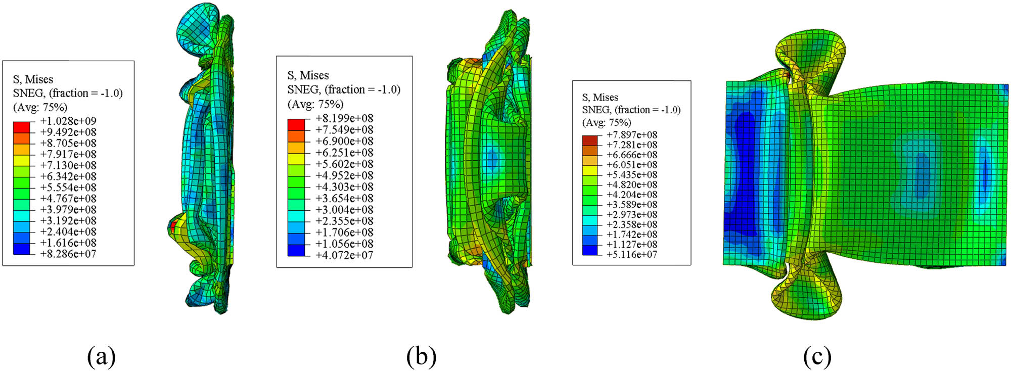
Comparison of stress value (MPa) of benchmark simulation at different velocities: (a) 9.68 m/s, (b) 6.05 m/s, and (c) 3.63 m/s.
3 Materials and methods
3.1 Sandwich geometry and material model
The panel shape design was modeled using ABAQUS/Explicit, with the geometrical parameters established in the previous study by Tak and Iqbal [53]. The thin-walled, squared, hollow sandwich panel was modeled using four-node S4R shell elements, with a thickness of 1 mm, an outer diameter of 63.05 mm, an inner diameter of 47.34 mm, and a height of 200 mm. The panel’s cross-sectional design is symmetrical, incorporating core geometries of circular, square, and hexagonal shapes. For the circular core design, the cores have a diameter of 7.855 mm, with 24 cores distributed evenly across the four sides of the cross-section. The square core design features cores with side lengths of 7.855 mm, totaling 20 cores symmetrically distributed along the four sides. The hexagonal core design adheres to the golden ratio rule (approximately 1.618), a principle commonly employed in creating hexagonal shapes. Each hexagonal core has a side length of 3.9275 mm, with 28 cores evenly distributed across the four sides of the cross-section. The spacing and dimensional aspects of all core designs are uniform and symmetrical, ensuring consistency across the cross-section. Detailed dimensions for each core shape are provided in Figure 2.
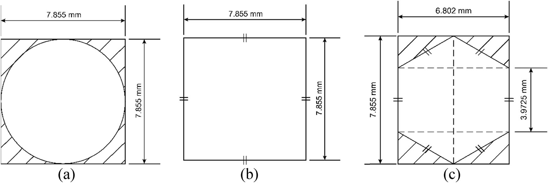
Core geometries: (a) circular core, (b) square core, and (c) hexagonal core.
The Johnson–Cook (J–C) damage model is a widely utilized phenomenological framework for predicting damage and failure in materials under various loading conditions [54]. This damage modeling is extensively employed in situations involving high strain rates, elevated temperatures, and significant deformations, such as metal forming, impact, and ballistic events. The J–C damage model defines damage initiation based on the critical threshold of the damage parameter (D) [55]. The damage parameter (D) is the accumulation of plastic strain
where D is the damage parameter,
where η is the triaxial stress, ϵ̇ is the strain rate, T is the temperature, and
J–C damage modeling also considers the effect of the carrier temperature relative to the yield temperature, which affects the material’s ductility. J–C damage modeling has an equivalent equation for von Mises stress shown in Eq. (4). The material parameters for each sandwich panel material utilized in the study are presented in Table 2.
| Parameter | ASTM A36 | AISI 1045 | AISI 52100 |
|---|---|---|---|
| Young’s modulus (E), N/m2 | 200 × 109 | 205 × 109 | 200 × 109 |
| Poisson’s ratio | 0.26 | 0.29 | 0.3 |
| Density (ρ), kg/m3 | 7,850 | 7,850 | 7,810 |
| Yield stress (A) (N/m2) | 250 × 106 | 506 × 106 | 774.48 × 10⁶ |
| Strain hardening coefficient (B), N/m2 | 477 × 106 | 320 × 106 | 134 × 106 |
| Strain hardening exponent (n) | 0.18 | 0.28 | 0.37 |
| Strain rate sensitivity coefficient (C) | 0.012 | 0.064 | 0.018 |
| Thermal softening exponent (mm) | 1 | 1.06 | 3.171 |
| Reference strain rate (
|
0.0001 | 0.0001 | 0.0001 |
| Melting temperature (T melt), K | 1,811 | 1,733 | 1,424 |
| Transition temperature (T transition), K | 300 | 300 | 300 |
| Fracture constant (D 1 ) | 0.403 | 0.1 | 0.0368 |
| Fracture constant (D 2 ) | 1.107 | 0.76 | 2.34 |
| Fracture constant (D 3 ) | −1.899 | −1.57 | −1.484 |
| Fracture constant (D 4 ) | 0.00961 | 0.005 | 0.0035 |
| Fracture constant (D 5 ) | 0.3 | −0.84 | 0.411 |
3.2 Dynamic load setting on the sandwich panel structure
The impactor is modeled as an undeformed rigid body, while the sandwich panel is modeled as a deformable body. The impactor is a solid cylinder with a diameter of 300 mm, a length of 631 mm, and a mass of 350 kg. The drop height of 4.78 m resulted in an impact velocity of 9.68 m/s, following the parameters established by Tak and Iqbal [53]. The simulation is conducted in ABAQUS Explicit with a dynamic analysis period of 0.1 s. The linear bulk viscosity parameter is set to 0.06, and the quadratic bulk viscosity parameter to 1.2. History outputs are defined for displacement changes (U2) and force magnitude (RF2). The tangential surface contact behavior between the impactor and the sandwich panel is modeled using penalty friction with an isotropic distribution and a friction coefficient of 0.03.
In contrast, normal contact is modeled as hard contact. The impactor is designated as the master surface, and the sandwich panel is defined as the slave surface, with standard discretization applied during the analysis. The displacement boundary condition allows movement only along the U2 axis for the axial surface of the sandwich panel in direct contact with the impactor. The crush boundary condition restricts motion along U1, U3, UR1, UR2, and UR3 (set to 0) for the axial face of the panel not in contact with the impactor. The boundary condition settings are illustrated in Figure 3. The initial velocity of the impactor is defined using a uniformly distributed velocity field restricted to translational motion. The velocity is assigned a value of −9.68 m/s in the U2 direction, with the negative sign indicating the downward direction of motion [58,59].
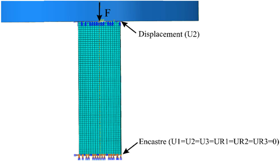
Compressive load and boundary condition settings.
3.3 Mesh convergence test
The mesh modeling settings were optimized to strike a balance between simulation processing time and accuracy [60]. Mesh elements were configured using four-point reduced integration S4R elements, which are suitable for shell modeling. Thickness was defined using a five-point integration method, applying Simpson’s rule for thickness integration. The resulting meshes for the sandwich panels with varying core shapes are depicted in Figure 4. This study analyzed the convergence of hexagonal core models made of ASTM A36 material. Maximum force values were used as the reference metric for each mesh size. The results were plotted on a mesh convergence graph, as shown in Figure 5. The mesh size range of 12–20 mm, resulting in a total number of elements ranging from 10,812 to 69,345, was observed to produce relatively consistent data, indicating an optimal mesh resolution for the simulation.
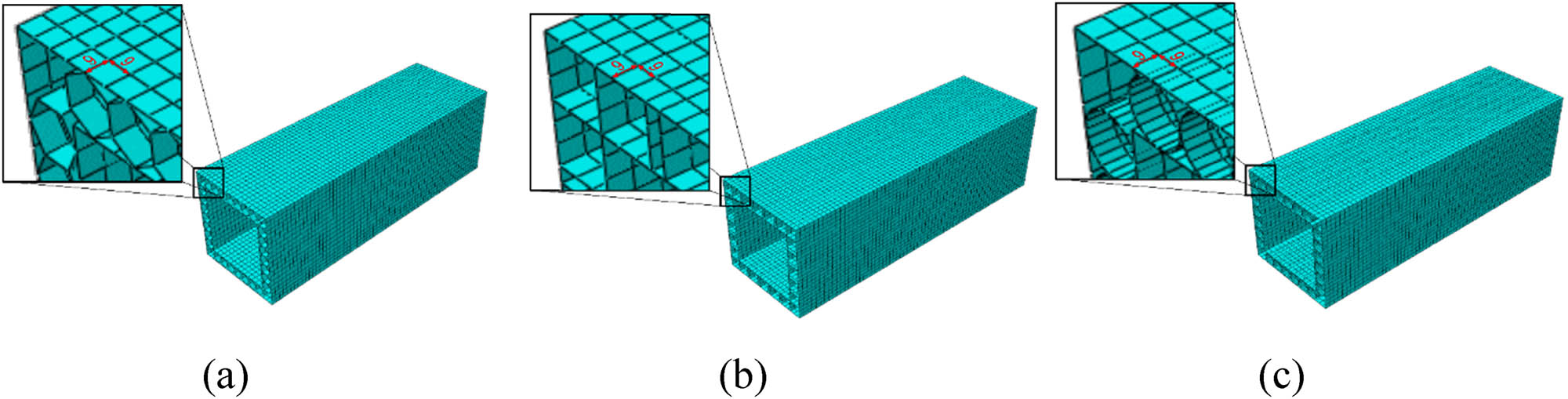
Mesh configuration in different core shapes: (a) hexagonal core, (b) square core, and (c) circular core.
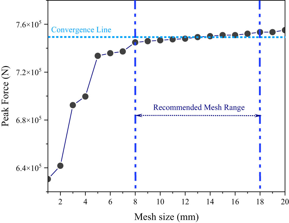
Mesh convergence results of hexagonal core models using ASTM A36 material.
4 Results and discussion
4.1 Simulation result on core shapes and material types
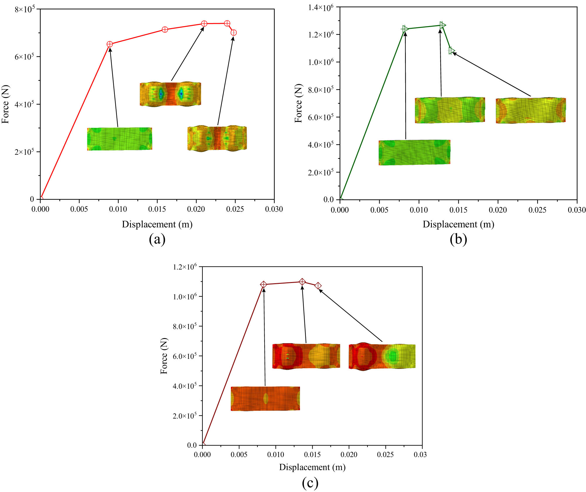
This study examines three core geometry modifications across three different material types. The forced displacement of the model under compressive load is included in the simulation results, along with progressive stress contours at specific locations for a comprehensive analysis. Contour plots are another tool used to depict strain distribution, enabling a thorough assessment of strain characteristics across various material and geometric changes. The mechanical performance of hexagonal core models made from ASTM A36, AISI 1045, and AISI 52100 under compressive stress is shown by the force–displacement curves in Figure 6. The highest strength is exhibited by AISI 1045, which suggests minimal ductility and greater load-bearing capacity due to its steep peak force and slight displacement. While AISI 52100 strikes a compromise between strength and ductility, exhibiting intermediate strength and ductility, ASTM A36 has the lowest strength but the highest ductility, deforming significantly before fracture.
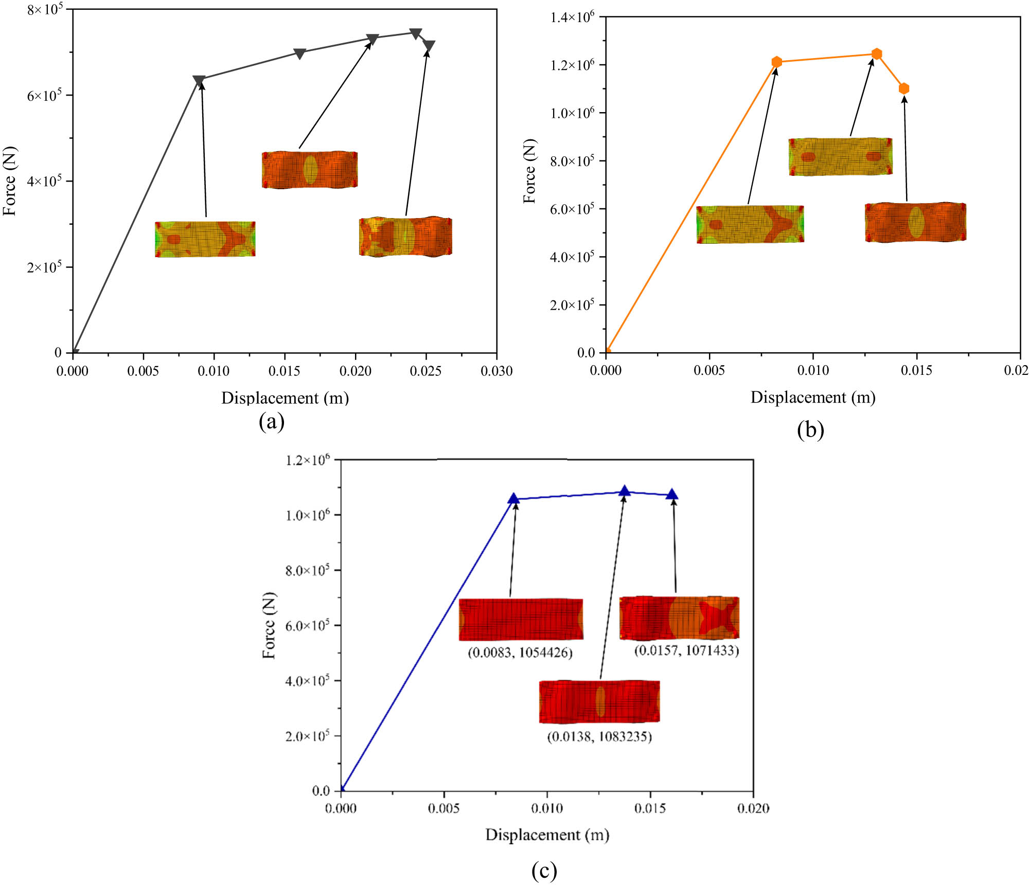
Force–displacement curves of the hexagonal core model: (a) ASTM A36, (b) AISI 1045, and (c) AISI 52100.
Furthermore, as shown in Figure 6, the stress contours throughout the force–displacement curve indicate various stages of structural behavior. Because the stress distribution throughout the elastic zone is uniform and low, with very modest localized concentrations in areas of geometric irregularity, the material remains within flat mode. As the peak force approaches, stress concentrations increase at the edges and corners of the hexagonal cells, indicating the onset of plastic deformation and localized buckling of the face plate. Deformation brought on by highly localized stress, particularly at critical locations such as the center or margins, indicates the onset of plastic collapse after the peak.
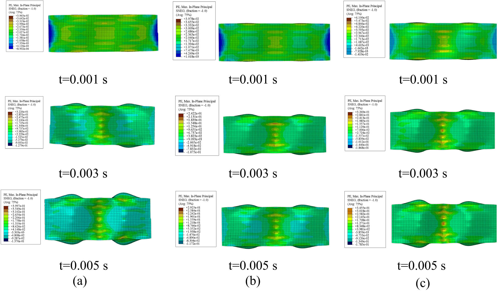
Figure 7 illustrates the strain contours of a hexagonal core model subjected to uniaxial compression over three distinct time intervals. The deformation modes include progressive folding, localized buckling, and plastic collapse, which are typical in uniaxial compression of thin-walled structures [61,62]. Each material demonstrates distinct strain distribution patterns over time, reflecting variations in mechanical properties. It can be found that strain concentration areas increase in intensity and size over time. The wider strain distribution in ASTM A36, a more ductile material, indicates energy absorption through plastic deformation. AISI 52100, a high-strength, low-ductility material, shows severe strain concentrations, indicating the possibility of brittle failure under sustained loading, whereas AISI 1045 exhibits intermediate behavior with moderate strain localization. The impact of material qualities on deformation and failure risk is highlighted by increasing strain intensities with time, especially at stress concentration places.
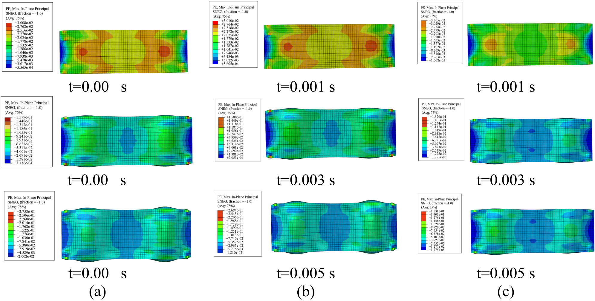
Strain contours of the hexagonal core model at different time intervals: (a) ASTM A36, (b) AISI 1045, and (c) AISI 52100.
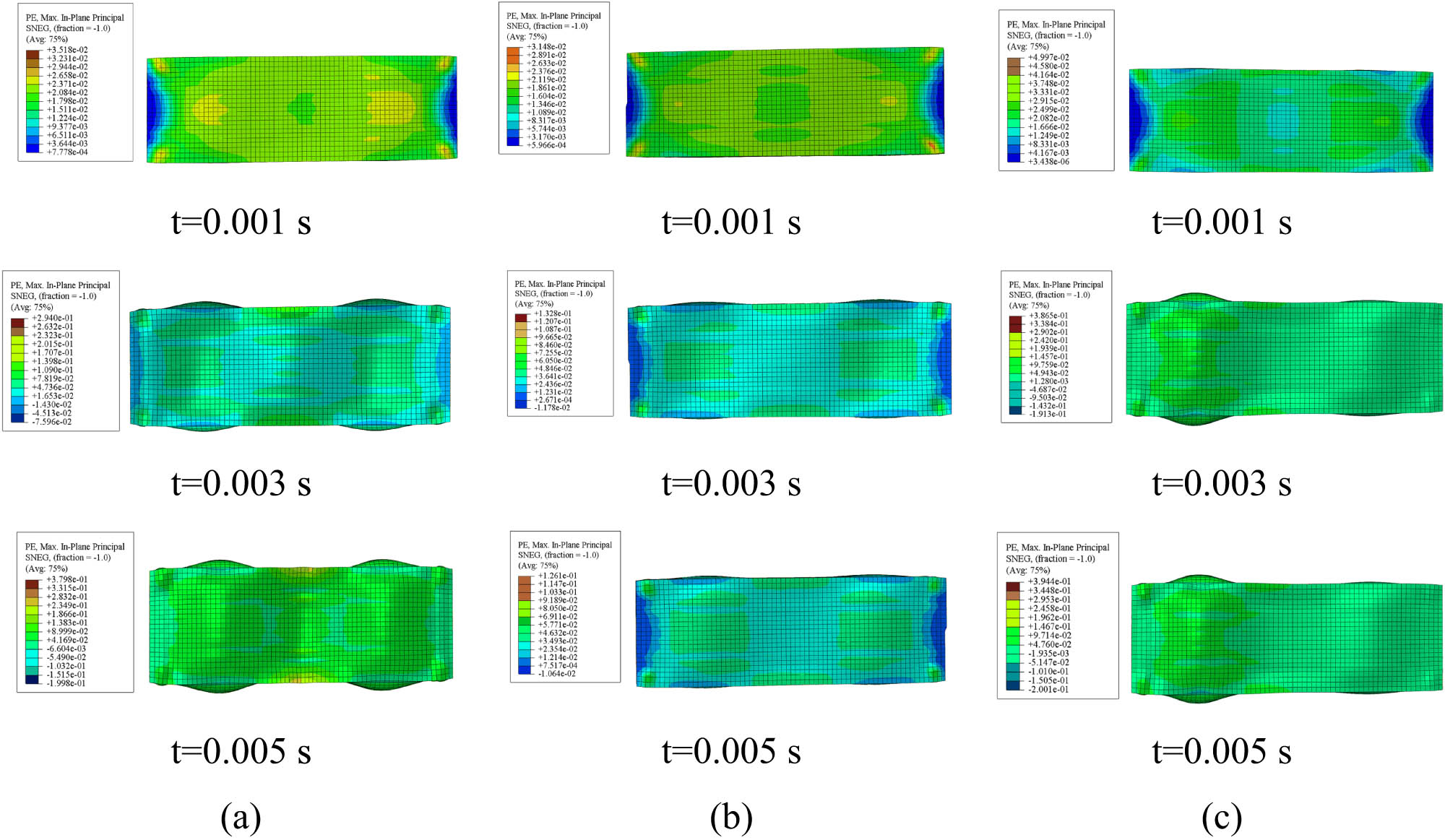
The force–displacement curves for the square core models depicted in Figure 8 demonstrate changes in mechanical behavior. ASTM A36 demonstrates a progressive increase in force with a more ductile behavior, attaining moderate force levels before exhibiting strain softening as displacement escalates. AISI 1045 exhibits a more pronounced increase in force, attaining a greater peak before softening, signifying enhanced stiffness and moderate ductility. AISI 52100 exhibits maximum strength but undergoes rapid reductions after peak loads, displaying high strength yet constrained ductility, with failure resulting from brittle characteristics. Stress contours for designated displacements indicate concentrated stress at the center and edges, highlighting material-specific deformation and potential failure modes: widespread plasticity in ASTM A36, localized yielding in AISI 1045, and brittle fractures in AISI 52100. Figure 9 illustrates that ASTM A36 exhibits extensive and increasingly distributed strain regions, with strain intensity incrementally increasing over time, indicating its ductile characteristics. AISI 1045 exhibits a more concentrated strain distribution, particularly in its central areas, indicating moderate stiffness and greater localized deformation compared to ASTM A36. AISI 52100 exhibits pronounced and concentrated strain concentrations, particularly in its center areas, attributable to its high strength and brittle characteristics, indicating restricted energy dissipation during plastic deformation. Strain intensities grow over time across all materials, although the distribution patterns vary distinctly, influenced by the specific mechanical properties of each material.
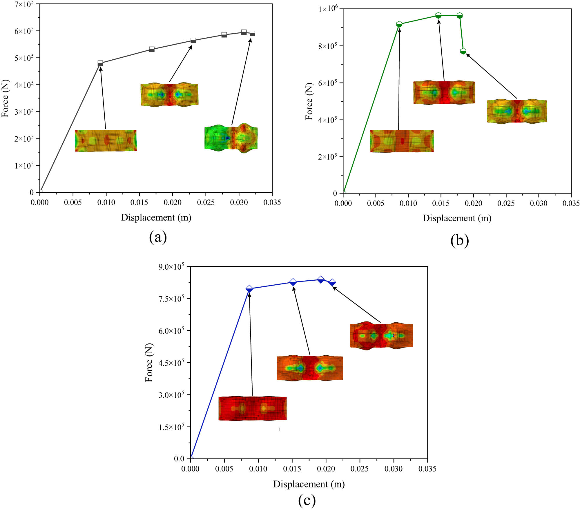
Force–displacement curve of the square core model: (a) ASTM A36, (b) AISI 1045, and (c) AISI 52100.
Strain contours of the square core model at different time intervals: (a) ASTM A36, (b) AISI 1045, and (c) AISI 52100.
The force–displacement curves for the circular core models demonstrate a similar phenomenon in the mechanical performance of various material types, as illustrated in Figure 10. ASTM A36, as depicted in Figure 10a, exhibits a consistent increase in force, reaching a moderate peak force before softening, which signifies ductile behavior characterized by significant energy absorption and delayed failure. AISI 1045, as illustrated in Figure 11b, exhibits a more pronounced force increase, reaching elevated peak forces due to its enhanced stiffness, followed by a gradual softening that indicates its intermediate ductility and strength. Conversely, AISI 52100 in Figure 10c achieves the maximum force values, exhibiting sudden decline post-peak, which indicates its considerable strength and brittle failure mode.
Force–displacement curves of the circular core model: (a) ASTM A36, (b) AISI 1045, and (c) AISI 52100.
Strain contours of the circular core model: (a) ASTM A36, (b) AISI 1045, and (c) AISI 52100.
Figure 11 illustrates a similar phenomenon, where the ASTM A36 model demonstrates a uniform strain distribution with progressive increases over time, exhibiting its ductility and capacity to absorb energy through extensive plastic deformation. The AISI 1045 model exhibits localized strain concentrations predominantly at the edge area, with increasing intensity over time, indicating its moderate ductility and elevated stiffness. The AISI 52100 model exhibits highly localized strain areas, especially at crucial stress locations, with limited dispersion, underscoring its brittleness and elevated strength. Strain intensity increases over time across all materials. However, levels and distribution patterns vary substantially due to their mechanical properties.
4.2 Overall discussion
The geometry size, shape configuration, and mechanical properties influence the mechanical behavior of the materials [63–65]. The force–displacement curves in Figure 12 compare the mechanical responses of three materials for different core shapes. Across all core shapes, AISI 52100 exhibits the highest peak forces due to its high strength, followed by AISI 1045. In contrast, ASTM A36 has the lowest peak force but demonstrates a more gradual slope, indicative of its ductility. All materials exhibit similar displacement capacities in the hexagonal core, with AISI 1045 achieving the highest force before sudden failure, reflecting its brittle behavior. In the square core, AISI 1045 leads in peak force again, but its abrupt drop highlights limited ductility, whereas ASTM A36 shows a balance of strength and moderate ductility. Overall, the circular shape yields higher peak forces than the hexagonal and square shapes, likely due to the uniform stress distribution inherent in circular geometry.
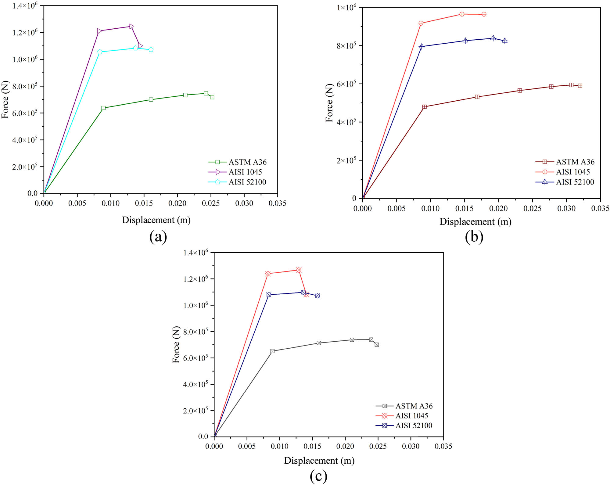
Comparison of force–displacement curves at different core shapes: (a) hexagonal, (b) square, and (c) circular.
Figure 13 highlights the force–displacement behavior of different core geometries made from ASTM A36, AISI 1045, and AISI 52100 materials. For ASTM A36, the hexagonal and circular cores exhibit the highest peak force, and the rectangular core shows the lowest strength but slightly higher ductility. In AISI 1045, all geometries achieve similar peak forces, with the rectangular core showing a marginal advantage in displacement capacity. For AISI 52100, the hexagonal and circular cores exhibit the highest peak forces, while the rectangular core demonstrates slightly lower strength with better ductility. Across all materials, circular and hexagonal cores generally show superior load-bearing capacity, while rectangular cores provide greater ductility. Table 3 presents a summary of failure modes across different core types. It can be observed that collapse response is primarily dictated by the core shape rather than the material types. While all three steels undergo the same sequence of events (initial yielding, core compaction, and overall folding), the way each stage develops differs according to whether the core cells are hexagonal, square, or circular.
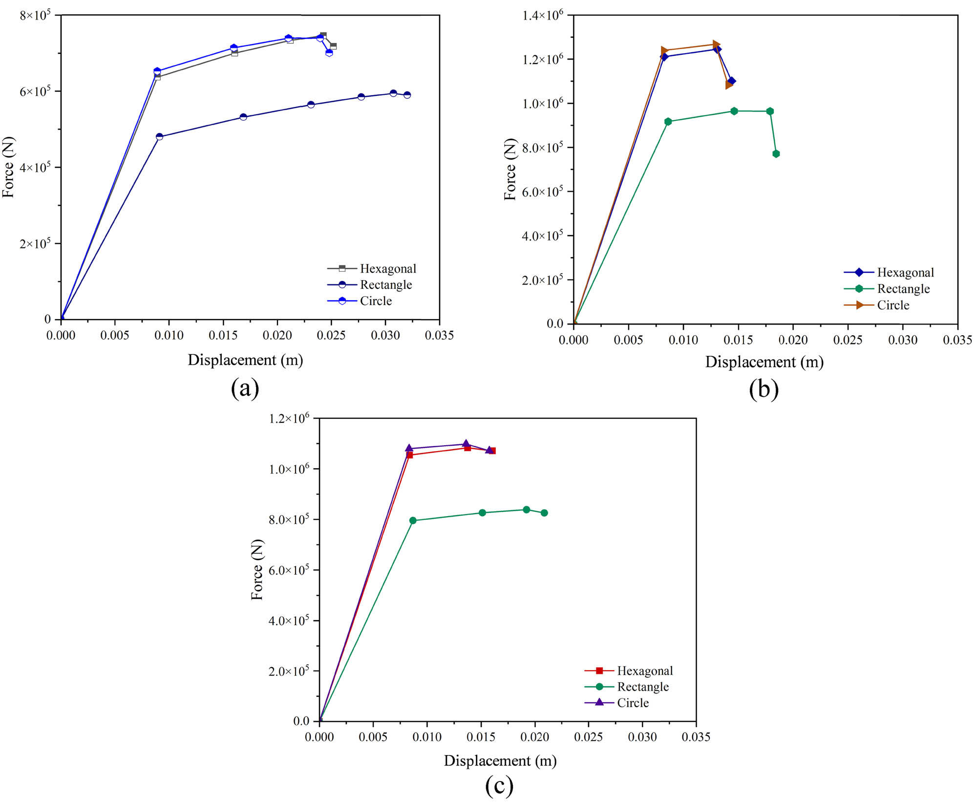
Force–displacement curves of different core types: (a) ASTM A36, (b) AISI 1045, and (c) AISI 52100.
Summary of failure modes between different core types
| Criterion | Hexagonal | Square | Circular |
|---|---|---|---|
| Onset of yielding | Simultaneous at cell-corner joints and evenly distributed plastic zone | Highly localized vertical bands along interior webs; ends stay mostly elastic | Two discrete circular patches near mid-width |
| Principal local-failure feature | Progressive bending/crushing of hexagon walls; plastic hinges form symmetrically | Buckling of square webs in a chess-board pattern; central indentation dominates | Uniform flattening of ring walls; the core densifies smoothly |
| Global collapse mode | Concertina-type folding with two to three regular plastic hinges | Diamond/asymmetric folding; one dominant hinge at mid-height and secondary hinges near ends | Barrel-type global bowing; diffuse hinges, gradual shortening, and smooth but lower-energy collapse |
| Energy-absorption efficiency | Highest – largest plateau area, thanks to uniform strain and sustained folding | Moderate to high local plastic strain, but with a shorter plateau and earlier densification | Moderately smoother curve; slightly lower specific energy absorption in ASTM A36 |
| Stability of post-peak response | Very stable (flat plateau and minimal load drop) | Less stable (pronounced oscillations after peak) | Stable but with a gently declining plateau |
5 Conclusions
A series of FEA results were conducted to investigate the impact of material selection and core shape on the structural performance of steel sandwich plates under uniaxial compressive loads. Three different materials, including ASTM A36, AISI 1045, and AISI 52100, and core types such as hexagonal, square, and circular cores were investigated using ABAQUS/Explicit. The results show that the same three-stage collapse progression, including local yielding, core crushing, and global folding, is observed for each material, where higher-strength steels merely delay each stage of collapse. Hexagonal cores deliver the most balanced compressive performance, producing the flattest and longest force plateau. In contrast, square cores experience the highest local strains, which can be beneficial for peak-load capacity but may lead to premature wall tearing if ductility is limited.
Future studies should expand this investigation to examine the behavioral influence of steel sandwich plates with various core designs, particularly in dynamic or collision contexts. Investigating enlarged core geometries, including truss-like or lattice structures, may yield more insights into their efficacy in energy absorption, impact resistance, and structural recovery. The impact of core-to-face sheet bonding and hybrid materials on improving the overall structural resilience requires investigation.
-
Funding information: This work was supported by the “Rencana Anggaran dan Kerja Tahunan” (RKAT) – Universitas Sebelas Maret Year 2025, under the Research Scheme of “Riset Kolaborasi Indonesia” (RKI), with a research grant/contract no. 431/UN27.22/PT.01.04/2025. Scientific collaboration with the Laboratory of Ship Safety Design at Pukyong National University, South Korea, is highly acknowledged for completing this work.
-
Author contributions: All authors have accepted responsibility for the entire content of this manuscript, consented to its submission to the journal, reviewed all the results, and approved the final version of the manuscript. Conceptualization: A.R.P., Q.T.D., and T.M.; methodology: T.T. and I.I.; formal analysis: A.A.P., M.A.F., and T.T.; resources: A.R.P., E.P.B., and T.T.; data curation: A.A.P. and M.A.F.; writing – original draft preparation: T.T. and A.R.P.; writing – review and editing: I.I. and J.M.S.; visualization: M.A.F. and I.I.; supervision: R.R., A.R.P., Q.T.D., and T.M.
-
Conflict of interest: The authors declare no conflict of interest.
-
Data availability statement: The datasets generated and/or analyzed during the current study are available from the corresponding author upon reasonable request.
References
[1] Pflug J, Verpoest I. Sandwich materials selection charts. J Sandwich Struct Mater. 2006;8:407–21. 10.1177/1099636206065521.Search in Google Scholar
[2] Bin Kamarudin MN, Mohamed Ali JS, Aabid A, Ibrahim YE. Buckling analysis of a thin-walled structure using finite element method and design of experiments. Aerospace. 2022;9:541. 10.3390/aerospace9100541.Search in Google Scholar
[3] Feng J, Fu J, Shang C, Lin Z, Li B. Sandwich panel design and performance optimization based on triply periodic minimal surfaces. Comput Des. 2019;115:307–22. 10.1016/j.cad.2019.06.007.Search in Google Scholar
[4] Nikkhah H, Baroutaji A, Kazancı Z, Arjunan A. Evaluation of crushing and energy absorption characteristics of bio-inspired nested structures. Thin-Walled Struct. 2020;148:106615. 10.1016/j.tws.2020.106615.Search in Google Scholar
[5] Teixeira P, Pina L, Rocha R, Sadek S. Parametric analysis of energy absorption capacity of thin aluminum plates impacted by rigid spherical projectiles. Thin-Walled Struct. 2021;159:107240. 10.1016/j.tws.2020.107240.Search in Google Scholar
[6] Tao Q, Ren P, Shi L, Zhao Z, Tang Y, Ye R, et al. Energy absorption and impact behavior of composite sandwich panels under high-velocity spherical projectile. Int J Impact Eng. 2022;162:104143. 10.1016/j.ijimpeng.2021.104143.Search in Google Scholar
[7] Kusuma Sarwoko AR, Prabowo AR, Ghanbari-Ghazijahani T, Thang Do Q, Ridwan R, Hanif MI. Buckling of thin-walled stiffened panels in transportation structures: benchmarking and parametric study. Eng Sci. 2024;30:1137. 10.30919/es1137.Search in Google Scholar
[8] Prabowo AR, Bae DM, Sohn JM, Cao B. Energy behavior on side structure in event of ship collision subjected to external parameters. Heliyon. 2016;2:e00192. 10.1016/j.heliyon.2016.e00192.Search in Google Scholar PubMed PubMed Central
[9] Ismail A, Zubaydi A, Piscesa B, Tuswan T. A novel fiberglass-reinforced polyurethane elastomer as the core sandwich material of the ship–plate system. J Mech Behav Mater. 2023;32:20220288. 10.1515/jmbm-2022-0288.Search in Google Scholar
[10] Tuswan T, Sari EN, Ismail A, Prabowo AR. Experimental evaluation on palm oil and sesame oil-based resin properties as core sandwich material for lightweight ship structure. Int J Eng. 2022;35:1690–8. 10.5829/IJE.2022.35.09C.03.Search in Google Scholar
[11] Kumar R, Patel S. Failure analysis on octagonal honeycomb sandwich panel under air blast loading. Mater Today Proc. 2021;46:9667–72. 10.1016/j.matpr.2020.07.525.Search in Google Scholar
[12] Santosa SP, Arifurrahman F, Izzudin MohH, Widagdo D, Gunawan L, Response analysis of blast impact loading of metal-foam sandwich panels. Procedia Eng. 2017;173:495–502. 10.1016/j.proeng.2016.12.073.Search in Google Scholar
[13] Alderliesten R, Rans C, Benedictus R. The applicability of magnesium based fibre metal laminates in aerospace structures. Compos Sci Technol. 2008;68:2983–93. 10.1016/j.compscitech.2008.06.017.Search in Google Scholar
[14] Easton M, Beer A, Barnett M, Davies C, Dunlop G, Durandet Y, et al. Magnesium alloy applications in automotive structures. JOM. 2008;60:57–62. 10.1007/s11837-008-0150-8.Search in Google Scholar
[15] Kananen M, Mäntyjärvi K, Keskitalo M, Hietala M, Järvenpää A, Holappa K, et al. Laser welded corrugated steel panels in industrial applications. Phys Procedia. 2015;78:202–9. 10.1016/j.phpro.2015.11.044.Search in Google Scholar
[16] McShane GJ, Radford DD, Deshpande VS, Fleck NA. The response of clamped sandwich plates with lattice cores subjected to shock loading. Eur J Mech - A/Solids. 2006;25:215–29. 10.1016/j.euromechsol.2005.08.001.Search in Google Scholar
[17] Wadley HNG. Multifunctional periodic cellular metals. Philos Trans R Soc A: Math, Phys Eng Sci. 2006;364:31–68. 10.1098/rsta.2005.1697.Search in Google Scholar PubMed
[18] Feng Y, Qiu H, Gao Y, Zheng H, Tan J. Creative design for sandwich structures: A review. Int J Adv Robot Syst. 2020;17:1–24. 10.1177/1729881420921327.Search in Google Scholar
[19] Mertani BMB, Keskes B, Tarfaoui M. Experimental analysis of the crushing of honeycomb cores under compression. J Mater Eng Perform. 2019;28:1628–38. 10.1007/s11665-018-3852-2.Search in Google Scholar
[20] Evans KE. The design of doubly curved sandwich panels with honeycomb cores. Compos Struct. 1991;17:95–111. 10.1016/0263-8223(91)90064-6.Search in Google Scholar
[21] Rokaya A, Kim J. An accurate analysis for sandwich steel beams with graded corrugated core under dynamic impulse. Int J Steel Struct. 2018;18:1541–59. 10.1007/s13296-018-0062-6.Search in Google Scholar
[22] Liu K, Zong S, Li Y, Wang Z, Hu Z, Wang Z. Structural response of the U-type corrugated core sandwich panel used in ship structures under the lateral quasi-static compression load. Mar Struct. 2022;84:103198. 10.1016/j.marstruc.2022.103198.Search in Google Scholar
[23] Haldar AK, Managuli V, Munshi R, Agarwal RS, Guan ZW. Compressive behaviour of 3D printed sandwich structures based on corrugated core design. Mater Today Commun. 2021;26:101725. 10.1016/j.mtcomm.2020.101725.Search in Google Scholar
[24] Sadikbasha S, Pandurangan V. High velocity impact response of sandwich structures with auxetic tetrachiral cores: Analytical model, finite element simulations and experiments. Compos Struct. 2023;317:117064. 10.1016/j.compstruct.2023.117064.Search in Google Scholar
[25] Wang Y, Zhao W, Zhou G, Wang C. Analysis and parametric optimization of a novel sandwich panel with double-V auxetic structure core under air blast loading. Int J Mech Sci. 2018;142–143:245–54. 10.1016/j.ijmecsci.2018.05.001.Search in Google Scholar
[26] Kintscher M, Kärger L, Wetzel A, Hartung D. Stiffness and failure behaviour of folded sandwich cores under combined transverse shear and compression. Compos Part A Appl Sci Manuf. 2007;38:1288–95. 10.1016/j.compositesa.2006.11.008.Search in Google Scholar
[27] Heimbs S, Cichosz J, Klaus M, Kilchert S, Johnson AF. Sandwich structures with textile-reinforced composite foldcores under impact loads. Compos Struct. 2010;92:1485–97. 10.1016/j.compstruct.2009.11.001.Search in Google Scholar
[28] Zarei Mahmoudabadi M, Sadighi M. Experimental investigation on the energy absorption characteristics of honeycomb sandwich panels under quasi-static punch loading. Aerosp Sci Technol. 2019;88:273–86. 10.1016/j.ast.2019.02.035.Search in Google Scholar
[29] Aydincak İ, Kayran A. An approach for the evaluation of effective elastic properties of honeycomb cores by finite element analysis of sandwich panels. J Sandw Struct & Mater. 2009;11:385–408. 10.1177/1099636209102891.Search in Google Scholar
[30] Zhou X, Jing L. Large deflection response of sandwich beams with layered-gradient foam cores subjected to low-velocity impact. Int J Impact Eng. 2023;172:104429. 10.1016/j.ijimpeng.2022.104429.Search in Google Scholar
[31] Chen L, Xie XZ, Li Z, Jin YQ. Research on crushing performance of sandwich panel with V-type corrugated core under shock load. Adv Mat Res. 2013;694–697:216–20. 10.4028/www.scientific.net/AMR.694-697.216.Search in Google Scholar
[32] Zangana S, Epaarachchi J, Ferdous W, Leng J, Schubel P. Behaviour of continuous fibre composite sandwich core under low-velocity impact. Thin-Walled Struct. 2021;158:107157. 10.1016/j.tws.2020.107157.Search in Google Scholar
[33] Giglio M, Gilioli A, Manes A. Numerical investigation of a three point bending test on sandwich panels with aluminum skins and NomexTM honeycomb core. Comput Mater Sci. 2012;56:69–78. 10.1016/j.commatsci.2012.01.007.Search in Google Scholar
[34] Ma Q, Rejab M, Siregar J, Guan Z. A review of the recent trends on core structures and impact response of sandwich panels. J Compos Mater. 2021;55:2513–55. 10.1177/0021998321990734.Search in Google Scholar
[35] Pascual C, Montali J, Overend M. Adhesively-bonded GFRP-glass sandwich components for structurally efficient glazing applications. Compos Struct. 2017;160:560–73. 10.1016/j.compstruct.2016.10.059.Search in Google Scholar
[36] Yu Y, Ying L, Hou W, Hu P, Jia X, Akhmet G. Failure analysis of adhesively bonded steel corrugated sandwich structures under three-point bending. Compos Struct. 2018;184:256–68. 10.1016/j.compstruct.2017.10.011.Search in Google Scholar
[37] Ghongade G, Kalyan KP, Vaira Vignesh R, Govindaraju M. Design, fabrication, and analysis of cost effective steel honeycomb structures. Mater Today Proc. 2021;46:4520–6. 10.1016/j.matpr.2020.09.694.Search in Google Scholar
[38] Dutra JR, Moni Ribeiro Filho SL, Christoforo AL, Panzera TH, Scarpa F. Investigations on sustainable honeycomb sandwich panels containing eucalyptus sawdust, Piassava and cement particles. Thin-Walled Struct. 2019;143:106191. 10.1016/j.tws.2019.106191.Search in Google Scholar
[39] Guo H, Yuan H, Zhang J, Ruan D. Review of sandwich structures under impact loadings: Experimental, numerical and theoretical analysis. Thin-Walled Struct. 2024;196:111541. 10.1016/j.tws.2023.111541.Search in Google Scholar
[40] Al Ali A, Arhore E, Ghasemnejad H, Yasaee M. Experimental and numerical investigation of multi-layered honeycomb sandwich composites for impact mechanics applications. Results Eng. 2024;21:101817. 10.1016/j.rineng.2024.101817.Search in Google Scholar
[41] Karsandik Y, Sabuncuoglu B, Yildirim B, Silberschmidt VV. Impact behavior of sandwich composites for aviation applications: A review. Compos Struct. 2023;314:116941. 10.1016/j.compstruct.2023.116941.Search in Google Scholar
[42] Vishnu Vardhan M, Venkata Prudhvi K, Srikanth U. Design and analysis of sandwich panel for different core shapes. Mater Today Proc. 2023;92:465–70. 10.1016/j.matpr.2023.03.594.Search in Google Scholar
[43] Burlayenko VN, Sadowski T. Influence of skin/core debonding on free vibration behavior of foam and honeycomb cored sandwich plates. Int J Non Linear Mech. 2010;45:959–68. 10.1016/j.ijnonlinmec.2009.07.002.Search in Google Scholar
[44] He W, Yao L, Meng X, Sun G, Xie D, Liu J. Effect of structural parameters on low-velocity impact behavior of aluminum honeycomb sandwich structures with CFRP face sheets. Thin-Walled Struct. 2019;137:411–32. 10.1016/j.tws.2019.01.022.Search in Google Scholar
[45] Raeisi S, Kadkhodapour J, Tovar A. Mechanical properties and energy absorbing capabilities of Z-pinned aluminum foam sandwich. Compos Struct. 2019;214:34–46. 10.1016/j.compstruct.2019.01.095.Search in Google Scholar
[46] Pingle SM, Fleck NA, Deshpande VS, Wadley HNG. Collapse mechanism maps for a hollow pyramidal lattice. Proc R Soc A Math Phys Eng Sci. 2011;467:985–1011. 10.1098/rspa.2010.0329.Search in Google Scholar
[47] Raeisi S, Tapkir P, Ansari F, Tovar A. Design of a hybrid honeycomb unit cell with enhanced in-plane mechanical properties. WCX SAE World congress experience, Detroit, Michigan, USA, 2019. p. 1–8. 10.4271/2019-01-0710.Search in Google Scholar
[48] Costanza G, Ferrigno S, Tata ME. Static compression study of honeycomb panel | Studio a compressione statica di pannelli honeycomb. Metall Ital. 2021;113:13–21.Search in Google Scholar
[49] Achache H, Kaci DA, Zahi R, Boughedaoui R. Mechanical behavior of sandwich panels with different core geometries under three-point bending. Struct Eng Mech. 2025;93:353–63. 10.12989/sem.2025.93.5.353.Search in Google Scholar
[50] Pedersen CBW, Deshpande VS, Fleck NA. Compressive response of the Y-shaped sandwich core. Eur J Mech A Solids. 2006;25:125–41. 10.1016/j.euromechsol.2005.06.001.Search in Google Scholar
[51] Nath SD, Nilufar S. Performance evaluation of sandwich structures printed by vat photopolymerization. Polymers. 2022;14:1513. 10.3390/polym14081513.Search in Google Scholar PubMed PubMed Central
[52] Zienkiewicz OC, Taylor RL, Zhu JZ. Field problems: a multidimensional finite element method. The finite element method: its basis and fundamentals. Oxford: Elsevier; 2013. p. 115–49. 10.1016/B978-1-85617-633-0.00005-8.Search in Google Scholar
[53] Tak SK, Iqbal MA. Axial compression behaviour of thin-walled metallic tubes under quasi-static and dynamic loading. Thin-Walled Struct. 2021;159:107261. 10.1016/j.tws.2020.107261.Search in Google Scholar
[54] Shutov AV, Klyuchantsev VS. Integral-based non-local approach to ductile damage and mixed-mode fracture. Eng Fract Mech. 2023;292:109656. 10.1016/j.engfracmech.2023.109656.Search in Google Scholar
[55] Kumar Reddy Sirigiri V, Yadav Gudiga V, Shankar Gattu U, Suneesh G, Mohan Buddaraju K. A review on Johnson Cook material model. Mater Today Proc. 2022;62:3450–6. 10.1016/j.matpr.2022.04.279.Search in Google Scholar
[56] Akbar Al Kautsar H, Pratama AA, Suryanto S, Prabowo AR, Adiputra R, Sukanto H, et al. Structural analysis of designed tubes under axial compression: variations of applied temperature, material type, and geometry design. Commun - Sci Lett Univ Zilina. 2024;26:B199–215. 10.26552/com.C.2024.036.Search in Google Scholar
[57] Al Kautsar HA, Adiputra R, Prabowo AR, Djordjevic B, Jurkovič M. Structural integrity of tapered cylindrical shell: Study case of tower wind turbine. E3S Web Conf. 2024;563:02033. 10.1051/e3sconf/202456302033.Search in Google Scholar
[58] Fu D, Wang L, Lv G, Shen Z, Zhu H, Zhu WD. Advances in dynamic load identification based on data-driven techniques. Eng Appl Artif Intell. 2023;126:106871. 10.1016/j.engappai.2023.106871.Search in Google Scholar
[59] Saba N, Jawaid M, Sultan MTH. An overview of mechanical and physical testing of composite materials. Mechanical and physical testing of biocomposites, fibre-reinforced composites and hybrid composites. Elsevier; 2019. p. 1–12. 10.1016/B978-0-08-102292-4.00001-1.Search in Google Scholar
[60] Zienkiewicz OC, Taylor RL, Zhu JZ. Automatic mesh generation. The Finite Element Method: its Basis and Fundamentals. Oxford, UK: Butterworth-Heinemann; 2013. p. 573–640. 10.1016/B978-1-85617-633-0.00017-4.Search in Google Scholar
[61] Zhang J, Yuan H, Qin Q, Ye Y, Wang T. Dynamic in-plane compression of asymmetric metal corrugated sandwich columns. Adv Eng Mater. 2020;22(3):1901159. 10.1002/adem.201901159.Search in Google Scholar
[62] Wang S, Li S, He J. Buckling behavior of sandwich hemispherical structure considering deformation modes under axial compression. Compos Struct. 2017;163:312–24. 10.1016/j.compstruct.2016.12.050.Search in Google Scholar
[63] Trong DN, Long VC, Ţălu S. The influence of shape and matrix size on the mechanical properties of the 2D epoxy thin film by Monte Carlo simulation method. AIP Adv. 2023;13:015209. 10.1063/5.0138329.Search in Google Scholar
[64] Hoc NQ, Trong DN, Cuong NC, Tinh BD, Long VC, Hien ND, et al. Determination of Young modulus and stress-strain curve for metal Fe and interstitial alloy FeC. J Compos Sci. 2022;6:250. 10.3390/jcs6090250.Search in Google Scholar
[65] Nguyen-Trong D. Z-AXIS deformation method to investigate the influence of system size, structure phase transition on mechanical properties of bulk nickel. Mater Chem Phys. 2020;252:123275. 10.1016/j.matchemphys.2020.123275.Search in Google Scholar
© 2025 the author(s), published by De Gruyter
This work is licensed under the Creative Commons Attribution 4.0 International License.
Articles in the same Issue
- Research Articles
- Probing microstructural evolution and surface hardening of AISI D3 steel after multistage heat treatment: An experimental and numerical analysis
- Activation energy of lime cement containing pozzolanic materials
- Optimizing surface quality in PMEDM using SiC powder material by combined solution response surface methodology – Adaptive neuro fuzzy inference system
- Experimental study of the mechanical shear behaviour of steel rebar connectors in timber–concrete structure with leafy wood species
- Development of structural grade lightweight geopolymer concrete using eco-friendly materials
- An experimental approach for the determination of the physical and mechanical properties of a sustainable geopolymer mortar made with Algerian ground-granulated blast furnace slag
- Effect of using different backing plate materials in autogenous TIG welding on bead geometry, microhardness, tensile strength, and fracture of 1020 low carbon steel
- Uncertainty analysis of bending response of flexoelectric nanocomposite plate
- Leveraging normal distribution and fuzzy S-function approaches for solar cell electrical characteristic optimization
- Effect of medium-density fiberboard sawdust content on the dynamic and mechanical properties of epoxy-based composite
- Mechanical properties of high-strength cement mortar including silica fume and reinforced with single and hybrid fibers
- Study the effective factors on the industrial hardfacing for low carbon steel based on Taguchi method
- Analysis of the combined effects of preheating and welding wire feed rates on the FCAW bead geometric characteristics of 1020 steel using fuzzy logic-based prediction models
- Effect of partially replacing crushed oyster shell as fine aggregate on the shear behavior of short RC beams using GFRP rebar strengthened with TRC: Experimental and numerical studies
- Micromechanic models for manufacturing quality prediction of cantula fiber-reinforced nHA/magnesium/shellac as biomaterial composites
- Numerical simulations of the influence of thermal cycling parameters on the mechanical response of SAC305 interconnects
- Impact of nanoparticles on the performance of metakaolin-based geopolymer composites
- Enhancing mechanical and thermal properties of epoxy-based polymer matrix composites through hybrid reinforcement with carbon, glass and steel
- Prevention of crack kinetic development in a damaged rod exposed to an aggressive environment
- Ideal strain gauge location for evaluating stress intensity factor in edge-cracked aluminum plates
- Experimental and multiscale numerical analysis of elastic mechanical properties and failure in woven fabric E-glass/polyester composites
- Optimizing piezoelectric patch placement for active repair of center-cracked plates
- Experimental investigation on the transverse crushing performance of 3D printed polymer composite filled aluminium tubes
- Review Articles
- Advancing asphaltic rail tracks: Bridging knowledge gaps and challenges for sustainable railway infrastructure
- Chemical stabilization techniques for clay soil: A comprehensive review
- Development and current milestone of train braking system based on failure phenomenon and accident case
- Rapid Communication
- The role of turbulence in bottom-up nanoparticle synthesis using ultrafast laser filamentation in ethanol
- Special Issue on Deformation and Fracture of Advanced High Temperature Materials - Part II
- Effect of parameters on thermal stress in transpiration cooling of leading-edge with layered gradient
- Development of a piezo actuator-based fatigue testing machine for miniature specimens and validation of size effects on fatigue properties
- Development of a 1,000°C class creep testing machine for ultraminiature specimens and feasibility verification
- Special Issue on Advances in Processing, Characterization and Sustainability of Modern Materials - Part II
- Surface integrity studies in microhole drilling of Titanium Beta-C alloy using microEDM
- Experimental investigation on bacterial concrete by using Cantabro loss and UPV
- Influence of gas nitriding on the surface layer of M50 NiL steel for aerospace-bearing applications
- Experimental investigation on the spectral, mechanical, and thermal behaviors of thermoplastic starch and de-laminated talc-filled sustainable bio-nanocomposite of polypropylene
- Synthesis and characterization of sustainable hybrid bio-nanocomposite of starch and polypropylene for electrical engineering applications
- Microstructural and mechanical characterization of Al6061-ZrB2 nanocomposites fabricated by powder metallurgy
- Effect of edge preparation on hardness and corrosion behaviour of AA6061-T651 friction stir welds
- Mechanical improvement in acetal composites reinforced with graphene nanotubes and Teflon fibers using loss functions
- Experimental investigation on the mechanical properties of aluminum-based metal matrix composites by the squeeze casting method
- Investigation on punch force–displacement and thickness changes in the shallow drawing of AA2014 aluminium alloy sheets using finite element simulations
- Influence of liquid nitriding on the surface layer of M50 NiL steel for bearing applications
- Mechanical and tribological analyses of Al6061-GO/CNT hybrid nanocomposites by combined vacuum-assisted and ultrasonicated stir casting method
- Strengthening of structures with bacterial concrete for effective crack repair and durability enhancement
- Unique approaches in developing novel nano-composites: Evaluating their mechanical and tribological characteristics
- Load-carrying capacity of highly compact rigid deployable booms
- Investigating the influence of SiC and B4C reinforcements on the mechanical and microstructural properties of stir-casted magnesium hybrid composites
- Evaluation of mechanical and performance characteristics of bitumen mixture using waste septage ash as partial substitute
- Mechanical characterization of carbon/Kevlar hybrid woven 3D composites
- Development of a 3D-printed cervical collar using biocompatible and sustainable polylactic acid
- Mechanical characterization of walnut shell powder-reinforced neem shell liquid composite
- Special Issue on Structure-energy Collaboration towards Sustainability Societies
- Effect of tunneling conductivity of CNTs on the EMI shielding effectiveness of nanocomposite in the C-band
- Evaluation of the effect of material selection and core geometry in thin-walled sandwich structures due to compressive strength using a finite element method
- Special Issue on Sustainability and Development in Civil Engineering - Part III
- The optimum reinforcement length for ring footing resting on sandy soils resisting inclined load
- Special Issue on Advanced Materials in Industry 4.0
- Cross-dataset evaluation of deep learning models for crack classification in structural surfaces
- Mechanical and antibacterial characteristics of a 3D-printed nano-titanium dioxide–hydroxyapatite dental resin-based composite