Microwave properties of natural rubber based composites containing carbon black-magnetite hybrid fillers
-
Ahmed A. Al-Ghamdi
 ,
Petrunka Malinova
,
Petrunka Malinova

Abstract
The paper presents the synthesis and characterization of a carbon black-magnetite hybrid filler. The complex study on the structure of the filler has shown the magnetite phase to be distributed both over the surface (inter-aggregately) and inside (intra-aggregately) the carbon black particles, thus forming a true hybrid material. The results from the investigations on the mechanical and microwave properties of natural rubber-based composites filled with the new hybrid filler have been also reported. They have been compared to those of a composite comprising the physical mixture of carbon black and magnetite (at the same ratio as in the hybrid filler). The determined microwave characteristics of the composite comprising the hybrid filler obtained reveal the possibility for its use in manufacturing elastomer-based microwave absorbers.
1 Introduction
Microwave absorbing composites find the following important applications: antenna techniques and production – for improving the antenna parameters; to protect humans and other biological objects from the harmful electromagnetic waves; military purposes – for anti-radar camouflage to reduce the radar cross section of objects; to improve the electromagnetic compatibility between different electronic devices to reduce undesirable reflections from objects and devices; to improve the shielding of enclosures and containers acting as gasket materials; and to cover the inside of test rooms (anechoic chambers) in order to achieve “free space” conditions for measurements of components and systems.
The main principles for developing microwave absorbing composites involve [1] the following: (i) finding a suitable dielectric matrix and a suitable conductive filler or a system of fillers, (ii) ensuring interaction between the composite and microwaves in the entire volume of the composite, (iii) ensuring that the matrix insulates completely the filler particles from each other, and (iv) using functional fillers with high dielectric and magnetic loss values.
The main requirements for such kind of composites are that they reflect minimum and absorb maximum electromagnetic energy. The ideal absorber has a broad frequency range of the absorbing energy, excellent weather stability characteristics, reliability, and capability to perform in a large temperature diapason. Most of the present-day microwave absorbing composites are produced with the use of a dielectric rubber matrix and specific functional fillers. Those fillers – carbon black, graphite, active carbon, short carbon or metal fibers, micro- and nanosized metal powders – possess high values of the imaginary part of the complex dielectric permittivity and/or magnetic permeability and absorb high-frequency energy [2], [3], [4], [5], [6], [7], [8], [9], [10], [11]. For the past few years, the composites containing both dielectric and magnetic fillers have been a well-considered topic in the field of electromagnetic interference (EMI) shielding and radar absorbing materials [12], [13], [14], [15], [16], [17]. As the electromagnetic radiation has both a dielectric and a magnetic component, it is obvious that both dielectric and magnetic materials absorb effectively microwave radiation. Therefore, it has been of interest to combine components of high dielectric and magnetic losses into a hybrid filler, which opens new opportunities of preparing modern microwave absorbers of specific properties.
Meng et al. [18] reported a hybrid microsphere, Fe-phthalocyanine oligomer/Fe3O4, that showed the maximum reflection loss of −31.1 dB at 8.6 GHz. Che et al. [19] also reported a maximum reflection loss of −18 dB at 9 GHz for nanocomposites containing CNT-CoFe2O4 hybrids, whereas the maximum reflection loss for CNT and CoFe2O4 was −6 dB and −8.3 dB, respectively. Obviously, the combination of a dielectric material with the hybrid filler comprising dielectric and magnetic components is a better microwave absorber than the filler comprising any of the particular components.
Our hypothesis has been that a hybrid carbon black-magnetite filler would facilitate the preparation of a composite possessing suitable microwave properties better than those of composites filled with an ordinary mixture of carbon black and magnetite. The latter two components have been chosen as carbon black, being a material of high dielectric losses, is a filler often used in manufacturing microwave absorbers [6], [8], [9] and because magnetite crystal structure follows an inverse spinel pattern with alternating octahedral and tetrahedral-octahedra layers. It is known that the octahedral sites in the magnetite structure contain ferrous and ferric species. The electrons coordinated with these iron species are thermally delocalized and migrate within the magnetite structure causing high conductivity exchange constants that range from −28 J·K to 3 J·K between tetrahedral/octahedral sites and octahedral/octahedral sites, respectively [20]. Resultant conductivities range from 104 to 105 Ω−1m−1. Magnetite’s Curie temperature is observed at 850 K. Below the Curie temperature, magnetic moments on tetrahedral sites, occupied by ferric species, are ferromagnetically aligned, while magnetic moments on octahedral sites, occupied by ferrous and ferric species, are antiferromagnetic and cancel each other; such combined behavior is termed ferrimagnetic [20]. The abovementioned allows the conclusion that the carbon black-magnetite hybrid filler will exhibit both high dielectric and high magnetic losses, which will ensure good microwave properties of the composites comprising it.
The paper presents the synthesis and characterization of a carbon black-magnetite hybrid filler. The results from the investigations on the mechanical and microwave properties of elastomer-based composites filled with the new combination have been also reported. The mechanical and microwave parameters of a composite filled with the physical mixture of carbon black and magnetite (at the same ratio as in the hybrid filler) have been also given for comparison.
2 Materials and methods
2.1 Materials
Natural rubber (NR) (SMR 10) was purchased from North Special Rubber Corporation of Hengshui, Hebei Province, China. Other ingredients such as zinc oxide (ZnO), stearic acid (SA), N-tert-butyl-2-benzothiazyl sulfenamide (TBBS) (Vulkacit NZ/EG, produced by Lanxess), and sulphur (S) were commercial grades and used without further purification.
Carbon black (Corax N 330, produced by Evonik) had particle diameter of 38–42 nm, specific surface area of 75–85 m2/g, oil absorption number of 95–105 ml/100 g, and density of 1.86 g/cm3. Magnetite containing 95–100% of Fe3O4 and 0–5% of silica, with particle size of −50 microns, was purchased from Inoxia, UK.
2.2 Carbon black-magnetite hybrid filler preparation
Fifty grams of carbon black and 50 of magnetite were loaded into a ball mill, and 500 ml of ethyl alcohol was poured over it. The mixture was homogenized for 2 h. The suspension thus obtained was dried at 50°C for 1 h. Then the temperature was raised to 200°C, and the drying continued for 2 more hours. The yield was ground in a ball mill for 2 h. After that, the grind was loaded into the reactor (shown in Figure 1) and heated at 440°C under 10−2 mm Hg vacuum for 2 h. If necessary, the product was ground once more in a ball mill.
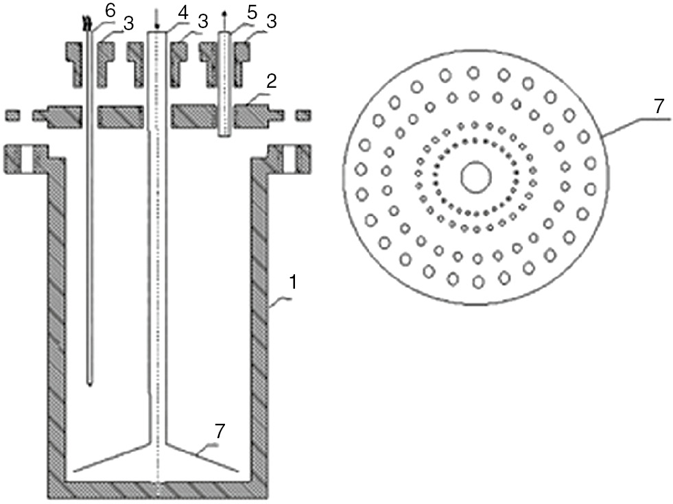
Design of the reactor used: 1 – reactor vessel, 2 – top (sealing flange), 3 – sealing nuts, 4 – gas inlet, 5 – gas outlet, 6 – thermocouple, 7 – Buchner funnel.
2.3 Carbon black-magnetite hybrid filler characterization
The following methods were used to characterize the filler:
iodine adsorption number – in correspondence to that of Ref. [21],
oil absorption number – in correspondence to that of Ref. [22],
specific surface area – calculated according to BET method [23], and
The average diameter of the mesopores and their size distribution were determined by the method of Barett-Joyner-Halenda (BJH) [27]. The texture characteristics were determined by low-temperature (77.4 K) nitrogen adsorption on a Quanta chrome Instruments NOVA 1200e (USA) apparatus. The nitrogen adsorption-desorption isotherms were analyzed to evaluate the following parameters: the specific surface areas (SBET) were determined on the basis of the BET equation, and the total pore volume (Vt) was estimated in accordance with the Gurvich rule at a relative pressure close to 0.99. Pore size distribution was calculated using the BJH method. The ash content of the carbon-magnetite filler was determined according to Ref. [28]. The ash from the filler was studied by complete silicate analysis, weight analysis, atomic absorption spectroscopy (AAS) (Perkin Elmer 5000, Perkin Elmer, Waltham, MA, USA), and inductively coupled plasma-optical emission spectroscopy (ICP-OES) (“Prodigy” High Dispersion ICP-OES, Teledyne Lemas Labs). Powder X-ray diffraction (XRD) patterns were collected at room temperature on a Bruker D8 (Billerica, MA, USA) Advance diffractometer using CuKα radiation and a LynxEye position sensitive detector (PSD) within the 5.3–80° 2θ range, step 0.04° 2θ, and 0.1 s/strip (total of 17.5 s/step) counting time. To improve the statistics, sample rotating speed of 30 rpm was used. Crystalline phases were identified by a DiffracPlus EVA 12 program (Bruker software) and International Center for Diffraction Data (ICDD) PDF-2 (2009) database. For ascertaining the distribution of carbon black and magnetite, the hybrid products were also investigated by scanning transmission electron microscope (STEM). Transmission electron microscope (TEM) investigations were performed on a TEM JEOL 2100 (Jeol USA, Inc.) instrument at accelerating voltage of 200 kV. The specimens were prepared by grinding and dispersing them in ethanol via ultrasonic treatment for 6 min. The suspensions were dripped on standard holey carbon/Cu grids (TED PELLA, Inc., USA). The measurements of lattice-fringe spacing recorded in high-resolution transmission electron microscopy (HRTEM) micrographs were made using digital image analysis of reciprocal space parameters. The analysis was carried out by Digital Micrograph software: TEM JEOL 2100; energy-dispersive X-ray spectroscopy (XEDS): Oxford Instruments, X-MaxN 80T; charge coupled device (CCD) Camera Orius 1000, 11 Mp, Gatan Inc. The ratio of magnetite to carbon counts was used as an estimate of the relative ranking of the amount of the two components in certain domains in the filler aggregates.
2.4 Preparation of composites containing carbon black-magnetite hybrid filler
The formulations of the NR-based compounds, containing a carbon-magnetite hybrid filler or the physical mixture of the same components, are shown in Table 1.
Formulation of the studied NR based compounds (in parts per 100 parts of rubber).
| Ingredients | ||
|---|---|---|
| 1. | NR (SMR-10) | 100 |
| 2. | Stearic acid | 2 |
| 3. | Zinc oxide | 3 |
| 4. | Carbon-magnetite filler/physical mixture | 70 |
| 5. | TBBSa | 1.5 |
| 6. | Sulphur | 2 |
aN-tert-butyl-2- benzothiazolesulfenamide.
Elastomer compounds were prepared on an open laboratory two rolls mill with rolls dimensions of L/D 320×160 and 1.27 friction. The turns of slowly rotating roll were 25 min−1. Test samples were vulcanized to plates with dimensions of 6 and 8 cm in vulcanization optimum, determined according to their vulcanization isotherms (ISO 3417:2010) at 160°C in an electrically heated vulcanization hydraulic press at 10 MPa on a steel made press form.
2.5 Characterization of the rubber based composites containing hybrid fillers
2.5.1 Mechanical properties
The mechanical properties of the vulcanized rubber composites were determined according to Ref. [29]. The Shore A hardness of the investigated rubber composites was determined according to Ref. [30].
2.5.2 Resistivity measurement
Volume resistivity (ρv, Ω·m) of the obtained flat rubber-based samples was measured using two electrodes (two-terminal method) and calculated by the equation:
where:
Rv – measured ohmic resistance between the electrodes, Ω;
S – cross sectional area of the measuring electrode, m2;
h – sample thickness between the electrodes, m.
The resistance was measured on a teraohmmeter Teralin III (produced in Germany), using direct current (Figure 2).

Scheme of the laboratory equipment for volume resistivity measurements.
The current voltage was 100 V. The resistance values were measured 1 min after switching on the current, when the resistance values were already stabilized. The measurements were carried out at ambient temperature. The samples used were circles with a diameter of 90 mm and thickness of 2 mm.
2.6 Microwave properties measurement
2.6.1 Reflection and attenuation
Measurements of reflection and attenuation were carried out using the measurement of output (adopted) power Pa in the output of a measuring line without losses, where samples of materials may be included. Because of the wide frequency measurement, a coaxial line was used. Samples of the materials were shaped into discs with an external diameter D=20.6 mm, equal to the outer diameter of the coaxial line and thickness of Δ≈2 mm. The internal diameter depended on the relative dielectric permittivity of the material.
The sample reflected a part of the incident electromagnetic wave with power Pin. The rest of the wave with power Pp penetrated the material, so that the attenuation L depended on the coefficient of reflection |Γ|. Its module was determined by a reflect meter.
Thus, the attenuation was determined by
where
The following scheme presents the equipment used for testing both parameters (Figure 3).

Scheme of the equipment for measuring the microwave properties. 1 – A set of generators for the whole range: HP686A and G4 – 79 to 82; 2 – coaxial section of the deck E2M Orion, with samples of material; 3 – power meter HP432A; 4 – scalar reflectance meter HP416A; R – reflect meter, including two directional couplers Narda 4222.16; two crystal detectors Narda 4503-N.
2.6.2 Shielding effectiveness (SE)
This parameter is defined as the sum of the reflection losses R, dB and attenuation L, dB in the material. It can be directly measured or calculated from the measured reflectance and attenuation in the material. In the first case, as measured, incident power on the sample Pin and adopted after the sample Pa, SE is determined by
In the second, if known, reflection and absorption in the material, SE, is determined by a definition as
where R, dB is the attenuation due to the reflection of power at the interfaces.
In the present work, the shielding effectiveness was determined by equation (5).
3 Results and discussion
3.1 Carbon black-magnetite hybrid filler characterization
Table 2 summarizes some properties of the obtained hybrid filler characterizing its specific features.
Properties of the carbon black-magnetite hybrid filler.
| Iodine adsorption (IA), mg/g | 44 |
| Oil absorption number (OAN), ml/100 g | 64 |
| Specific surface area (BET), m2/g | 42 |
| Ash content, % | 50.15 |
| Mesopore volume, cm3 (STPa)/g | 0.25 |
| Diameter of mesopores, nm | 2.4 |
aSTP-Standard temperature and pressure.
Noteworthy is that the oil absorption number of the hybrid filler is lower if compared to the one of neat carbon black used as a substrate (95–105 ml/100 g). This evidences that the distribution of magnetite phase over the carbon one is what lessens its proneness to form secondary structures (aggregates and agglomerates). As it will be shown below, the effect benefits the microwave properties of the composite. The results from the analyses (silicate analysis, AAS, and ICP-OES) of the filler ashes are presented in Table 3.
Silicate analysis, AAS, and ICP-OES (in %) of the carbon black-magnetite hybrid filler ashes.
| Fe3O4 | 72.60 ±0.001 |
| SiO2 | 22.29±0.10 |
| Al2O3 | 1.00±0.003 |
| CaO | 0.54±0.001 |
| MgO | 0.06±0.001 |
| BaO | 1.24±0.001 |
| Na2O | 0.08±0.01 |
| K2O | 0.08±0.001 |
| TiO2 | 0.08±0.0001 |
| ZnO | 0.47±0.0001 |
| MnO | 0.36±0.001 |
| NiO | 0.05±0.001 |
| Cr2O3 | 0.04±0.001 |
| CuO | 0.04±0.001 |
| PbO | <0.01 |
| Bi2O3 | 0.19±0.001 |
| Heat losses, 1000°C | 0.84±0.10 |
As expected, the ashes contain mostly magnetite and silica, which have not undergone changes because of the temperature at which the ash content is determined. It is also seen that the initial carbon-magnetite ratio has not changed (Table 2). That fact is also important.
The texture analysis and texture characteristics of the obtained hybrid filler are plotted in Figures 4 and 5.

Dependence of adsorbed gas volume on cm3/g, on relative pressure p/p0 (black line – adsorption branch of the sorption isotherm; red line – desorption branch).

Dependence of derivative volume dV on pore size, nm.
The broad hysteresis in the saturation zone (Figure 4) shows that the pores in the hybrid filler are a secondary formation resultant from the aggregation of the two phases. On the other hand, the narrow hysteresis allows the supposition that the pores are intra-aggregate ones and quite few. That is also confirmed by the reversible desorption branch of the sorption isotherm. The mesopore size distribution curve in Figure 5 shows that the size of the intra-aggregate pores varies in a large range (except for those up to 7 nm). They result from the interpenetration and aggregation of magnetite and carbon black, while the pores of smaller diameter are most probably entirely carbon black aggregates.
It is doubtless that energy dispersive X-ray (EDX) spectroscopy using a STEM or STEM-EDX is the most appropriate research approach to the characterization of hybrid fillers phase. The high angle annular dark field (HAADF) in STEM imaging displays the compositional contrast resulting from elements of different atomic number and their distribution. EDX allows identifying the particular elements and their relative proportions. Initial EDX analysis usually involves the generation of an X-ray spectrum from the entire scan area of the STEM image. The Y-axis shows the counts (number of X-rays received and processed by the detector), and the X-axis shows the energy of those X-rays. In addition, EDX software can:
keep the electron beam stationary on a spot or on a series of spots and generate spectra that will provide more localized elemental information,
have the electron beam follow a line drawn on the sample image and generate a plot of the relative proportions of different elements along that line (one-dimensional line scanning), and
map the distribution and relative proportion (intensity) of different elements over the scanned area (two-dimensional mapping).
Modern software now collects entire cumulative spectra from each point, so element choices can be made post-acquisition.
The representative HAADF image and compositional maps of the carbon black-magnetite hybrid filler are shown in Figure 6. The bright field TEM images of the same sample are shown in Figure 7.

HAADF image (A) and compositional maps (B, C, D) of the carbon black-magnetite hybrid filler.

Bright field TEM images at different magnifications (A–D). (A) ×10,000; (B) ×25,000; (C) ×250,000; (D) ×500,000.
As the images in Figures 6 and 7 show, the magnetite phase is evenly distributed among the carbon black agglomerates, in some cases, penetrating them. The latter fact is proven by the high-resolution TEM micrographs (Figure 7C and D), which picture how the magnetite phase penetration had disturbed the structural orderliness and homogeneity of the layers building the elemental particles of carbon black.
The areas where energy dispersive spectra on STEM of the carbon black-magnetite filler were scanned are shown in Figures 8 and 9. Table 4 presents the content of elements carbon, oxygen, and iron in atom percents.

EDS on STEM of carbon-magnetite hybrid filler: spectra positions (136–144).

EDS on STEM of carbon-magnetite hybrid filler: spectra positions (145–148).
Content of the elements carbon, oxygen and iron in the areas where spectra nos. 136–148 were scanned.
| Spectrum no. | C, at. % | O, at. % | Fe, at. % |
|---|---|---|---|
| 136 | 84.50 | 9.02 | 1.77 |
| 137 | 74.67 | 15.82 | 7.69 |
| 138 | 86.79 | 7.85 | 2.70 |
| 139 | 99.47 | 0.10 | – |
| 140 | 90.00 | 6.18 | 1.84 |
| 141 | 84.40 | 9.52 | 4.52 |
| 142 | 96.38 | 2.05 | 0.40 |
| 143 | 85.83 | 8.92 | 2.34 |
| 144 | 99.34 | 0.21 | – |
| 145 | 69.89 | 19.08 | 8.53 |
| 146 | 69.18 | 17.37 | 10.57 |
| 147 | 88.33 | 6.25 | 3.28 |
| 148 | 97.88 | 1.14 | – |
The analysis in Figures 8 and 9 and the comparison of the spectral data in Table 4 confirm that the magnetite phase (the darker one) is distributed both among the carbon particles and in the carbon aggregates. With some exceptions (spectra nos. 139, 142, 144, 148), the carbon phase is evenly distributed and is visibly present in the spectra.
It has been also important to establish the difference between the behavior of the hybrid filler and physical mixture of its components upon X-ray irradiation. The X-ray diffractograms of the fillers (Figures 10 and 11, respectively) indicate such a difference in the form of texture changes in the hybrid filler caused by thermal activation during its synthesis. The thermal treatment yields a more pronounced texture, but new phases are not formed.

X-ray diffraction pattern of the obtained hybrid filler.

X-ray diffraction pattern of the physical mixture carbon black-magnetite.
3.2 Mechanical properties
The mechanical properties of the investigated NR composites are summarized in Table 5. The vulcanizates comprising hybrid filler have Modulus 100 (M100) and tensile strength values higher than those of the vulcanizates comprising the physical mixture of carbon black and magnetite. Elongation at break of NR composites containing the hybrid filler is lower than that for the composites containing physical mixture of carbon black and magnetite.
Mechanical Properties of composites comprising the hybrid carbon black-magnetite filler and of composites filled with the physical mixture of carbon black and magnetite.
| NR composites containing hybrid filler | NR composites containing physical mixture of carbon black and magnetite | |
|---|---|---|
| M100, MPa | 3.9 | 3.0 |
| Tensile strength, MPa | 13.8 | 12.1 |
| Elongation at break, % | 275 | 290 |
| Residual elongation, % | 7 | 8 |
| Shore A hardness | 67 | 67 |
The table also shows the advantage of the dual-phase filler to the physical mixture of the components at the same ratio. Obviously, the thermal treatment at 440°C under vacuum to which the hybrid filler has been subjected favors its texture characteristics, mainly its micropores/mesopores ration and its mesopores size. The larger mesopores of the hybrid filler (Figure 5) facilitate enhanced elastomer-filler interaction, which in turn explains the achieved better physicomechanical properties.
3.3 Resistivity measurement
The data from the measurements on the specific volume resistance and surface resistance of composites comprising the hybrid carbon black-magnetite filler and of composites filled with the physical mixture of carbon black and magnetite are presented in Table 6.
Specific volume resistance and surface resistance of composites comprising the hybrid carbon black-magnetite filler and of composites filled with the physical mixture of carbon black and magnetite.
| Filler | Specific volume resistance, ρv, Ω·m | Specific surface resistance, ρs, Ω |
|---|---|---|
| Physical mixture | 1.1×10⁵ | 5.2×10⁸ |
| Hybrid filler | 4.2×10⁶ | 1.2×10⁹ |
The considerable difference in the specific volume resistance and surface resistance of the composites is obvious in Table 6. Carbon black conductivity is higher than that of magnetite [20], and the data in the table confirm the supposition that the latter is distributed intra-aggregately and inter-aggregately with regard to the carbon phase and limits the contacts between its electroconductive structures. As a result, the total electrical conductivity of the hybrid filler decreases and the specific surface resistance increases, respectively.
3.4 Microwave properties measurement
Figures 12–14 summarize the microwave properties of the composites studied within the 1–12-GHz frequency range.
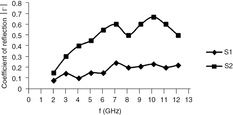
Frequency dependence of reflection coefficients |Γ| of a composite containing a carbon black-magnetite hybrid filler (S 1) and a composite containing a physical mixture (S 2).

Frequency dependence of attenuation coefficients of electromagnetic waves α of a composite containing carbon black-magnetite hybrid filler (S 1) and of a composite containing the physical mixture (S 2).

Frequency dependence of shielding effectiveness, SE, of a composite containing carbon black-magnetite hybrid filler (S 1) and a composite containing their physical mixture (S 2).
The coefficients of reflection of a composite containing carbon black-magnetite hybrid filler (denoted as S 1) and of a composite containing the physical mixture (denoted as S 2) depending on frequency are shown in Figure 12.
The attenuation coefficients of a composite containing carbon black-magnetite hybrid filler (S1) and of a composite containing the physical mixture (S 2) depending on frequency are shown in Figure 13.
As seen in Figure 12, the values of the reflection coefficient of both composites increase with the increasing frequency. The increase in the values of composite S 1 is from 0.075 to 0.22, while in those of composite S 2, it is from 0.15 to 0.65. The increase in the values of the attenuation coefficient (Figure 13) with the increasing frequency is more pronounced. That concerns a rather large frequency range (1–12 GHz) and, first of all, frequencies over 6 GHz. The attenuation coefficient values over 30 dB/cm in the 8–12-GHz frequency range allow the statement that the NR-based composite we have prepared and the hybrid carbon black-magnetite filler do possess microwave absorption properties.
The EMI of a composite containing carbon black-magnetite hybrid filler and a composite containing physical mixture depending on frequency is shown in Figure 14.
The composite containing the physical mixture has rather low SE values (between 1.02 and 6.32), while the one containing the hybrid filler having SE values between 10 and 22 dB facilitates effective shielding. The results show that the composite containing carbon black-magnetite hybrid filler exhibits exceptional broadband properties (practically throughout the entire investigated range) in terms of the effectiveness of electromagnetic shielding.
4 Conclusions
A hybrid carbon black-magnetite filler comprising components both of high dielectric and magnetic losses has been synthesized.
The number of parameters determined and the complex study on the structure of the filler have shown that the magnetite phase is distributed both over the carbon black particles (inter-aggregately) and inside (intra-aggregately) forming a true hybrid material.
The determined microwave characteristics of a composite comprising the hybrid filler obtained – coefficients of reflection, coefficient of attenuation, and shielding effectiveness – reveal the perceptiveness of the filler and its possible use for manufacturing elastomer-based microwave absorbers. The newly synthesized hybrid filler surpasses the physical mixture of the components it comprises in terms of microwave shielding effectiveness.
Acknowledgments
The work is a part of a project funded by King Abdulaziz University, Saudi Arabia, under grant number MB/11/12/436. The authors acknowledge the provided technical and financial support.
References
[1] Dishovsky N. J. Univ. Chem. Technol. Metal. 2009, 44, 115–122.Search in Google Scholar
[2] ECCOSORB Principles. Available at: http://www.eccosorb.com/notes-eccosorb-principles.htm.Search in Google Scholar
[3] Dual-band flexible rubber sheet absorber. Available at: http://www.eccosorb.eu/sites/default/files/techbulletins/rfp-ds-slj_112515.pdf.Search in Google Scholar
[4] FerroSorb EMC Absorbers. Available at: http://www.ets-lindgren.com/emcabsorbers.Search in Google Scholar
[5] Shtarkova R, Dishovsky N. J. Elastom Plast. 2009, 41, 163–174.10.1177/0095244308092439Search in Google Scholar
[6] Dishovsky N, Grigorova M. Mater. Res. Bull. 2000, 35, 403–409.10.1016/S0025-5408(00)00230-0Search in Google Scholar
[7] Zhang CS, Ni QQ, Fu SY, Kurashiki K. Compos. Sci. Technol. 2007, 67, 2973–2980.10.1016/j.compscitech.2007.05.011Search in Google Scholar
[8] Attharangsan S, Ismail H, Baka MA, Ismail J. Polym. Plast. Technol. Eng. 2012, 51, 655–662.10.1080/03602559.2012.662256Search in Google Scholar
[9] Ling Q, Sun J, Zhao Q, Zhou Q. Polym. Plast. Technol. Eng. 2011, 50, 89–94.10.1080/03602559.2010.531416Search in Google Scholar
[10] Das TK, Prusty S, Polym. Plast. Technol. Eng. 2012, 51, 1487–1500.10.1080/03602559.2012.710697Search in Google Scholar
[11] Chandran SA, Narayanankutty SK, Mohanan P. Polym. Plast. Technol. Eng. 2011, 50, 453–458.10.1080/03602559.2010.543229Search in Google Scholar
[12] Liu XG, Li B, Geng DY, Cui WB, Yang F, Xie ZG, Kang DJ, Zhang ZD. Carbon 2009, 47, 470–474.10.1016/j.carbon.2008.10.028Search in Google Scholar
[13] Kim JH, Kim SS. J. Alloys Comp. 2011, 509, 4399–4403.10.1016/j.jallcom.2011.01.050Search in Google Scholar
[14] Shi GM, Zhang JB, Yu DW, Chen LS. Adv. Mat. Research 2011, 299–300, 739–742.10.4028/www.scientific.net/AMR.299-300.739Search in Google Scholar
[15] Kavanloui M, Hashemi B. Mat. Design 2011, 32, 4257–4261.10.1016/j.matdes.2011.04.019Search in Google Scholar
[16] Liu Z, Bai G, Huang Y, Ma Y, Du F, Li F, Guo T, Chen Y. Carbon 2007, 45, 821–827.10.1016/j.carbon.2006.11.020Search in Google Scholar
[17] Li N, Huang Y, Du F, He X, Lin X, Gao H, Ma Y, Li F, Chen Y, Eklund PC. Nano Lett. 2006, 6, 1141–1145.10.1021/nl0602589Search in Google Scholar PubMed
[18] Meng F, Zhao R, Zhan Y, Lei Y, Zhong J, Liu X. Appl. Surf. Sci. 2011, 257, 5000–5006.10.1016/j.apsusc.2011.01.010Search in Google Scholar
[19] Che RC, Zhi CY, Liang CY, Zhou XG. Appl. Phys. Lett. 2006, 88, 033105/1–033105/3.10.1063/1.2165276Search in Google Scholar
[20] Cornell RM, U. Schwertmann, The Iron Oxides. VCH Press: Weinheim, Germany, 1996.Search in Google Scholar
[21] ISO 15651/1-91.Search in Google Scholar
[22] Bulgarian State Standard 9665:1176.Search in Google Scholar
[23] Brunauer S, Emmett PH, Teller E. J. Am. Chem. Soc. 1938, 60, 309–319.10.1021/ja01269a023Search in Google Scholar
[24] Gurvich LJ. Zh. Russ. Fiz-Khim. Obshchestva Chem. 1915, 47, 805–827.Search in Google Scholar
[25] Rouquerol F, Rouquerol J, Sing KSW. Adsorption by Powders and Porous Solids, Academic Press: London, UK, 1999.Search in Google Scholar
[26] Lowell S, Shields J, Thomas MA, Thommes M. Characterization of Porous Solids and Powders: Surface Area, Pore Size and Density, Springer: Netherlands, 2004.10.1007/978-1-4020-2303-3Search in Google Scholar
[27] Barrett EP, Joyner LG, Halenda PP. J. Am. Chem. Soc. 1951, 73, 373–380.10.1021/ja01145a126Search in Google Scholar
[28] ISO 1125:1999.Search in Google Scholar
[29] ISO 37: 2011.Search in Google Scholar
[30] ISO 7619-1:2010.Search in Google Scholar
©2018 Walter de Gruyter GmbH, Berlin/Boston
This article is distributed under the terms of the Creative Commons Attribution Non-Commercial License, which permits unrestricted non-commercial use, distribution, and reproduction in any medium, provided the original work is properly cited.
Articles in the same Issue
- Frontmatter
- Original articles
- Review of the mechanical performance of variable stiffness design fiber-reinforced composites
- Exact solution for bending analysis of functionally graded micro-plates based on strain gradient theory
- Synthesis, microstructure, and mechanical properties of in situ TiB2/Al-4.5Cu composites
- Microstructure and properties of W-Cu/1Cr18Ni9 steel brazed joint with different Ni-based filler metals
- Drilling studies on the prepared aluminum metal matrix composite from wet grinder stone dust particles
- Studies on mechanical properties of thermoplastic composites prepared from flax-polypropylene needle punched nonwovens
- Design of and with thin-ply non-crimp fabric as building blocks for composites
- Effect of coir fiber reinforcement on mechanical properties of vulcanized natural rubber composites
- Investigation and analysis of glass fabric/PVC composite laminates processing parameters
- Abrasive wear behavior of silane treated nanoalumina filled dental composite under food slurry and distilled water condition
- Finite element study into the effects of fiber orientations and stacking sequence on drilling induced delamination in CFRP/Al stack
- Preparation of PAA/WO3 composite films with enhanced electrochromism via layer-by-layer method
- Effect of alkali treatment on hair fiber as reinforcement of HDPE composites: mechanical properties and water absorption behavior
- Integration of nano-Al with one-step synthesis of MoO3 nanobelts to realize high exothermic nanothermite
- A time-of-flight revising approach to improve the image quality of Lamb wave tomography for the detection of defects in composite panels
- The simulation of the warpage rule of the thin-walled part of polypropylene composite based on the coupling effect of mold deformation and injection molding process
- Novel preparation method and the characterization of polyurethane-acrylate/ nano-SiO2 emulsions
- Microwave properties of natural rubber based composites containing carbon black-magnetite hybrid fillers
- Simulation on impact response of FMLs: effect of fiber stacking sequence, thickness, and incident angle