Mechanical characterization of carbon/Kevlar hybrid woven 3D composites
-
Gandham Ram Vishal
 ,
Ramraj Santhanakrishnan
,
Ramraj Santhanakrishnan

Abstract
This research work focuses on the experimental analysis for mechanical characterization of 3D woven carbon, Kevlar, and their hybrid composite laminates. According to the research, in 3D weaving, weft, warp, and binder fibers meet along and through the fabrics within the X, Y, and Z directions, respectively. The effect of different combinations of weft, warp, and binder with respect to 3D woven composites in terms of tensile strength, flexure strength, fracture toughness, and impact energy is analyzed in this study. The primary objective of this research is to fabricate four combinations of 3D woven composite fabrics from carbon and Kevlar fibers using hand weaving and a vacuum bagging method, keeping the weaving of the binder at 45°, with respect to weft and warp. On testing the combinations, the CCK specimen provided a higher tensile modulus and peak stress with a medium strength to weight ratio. It reflects the ability of the CCC combination under bending to compress or stretch less when experiencing deformation (strain), while the maximum values (stress) indicate that the CCC can support a larger load. KKC shows the synergistic effect of the fibers, excellent interfacial bond strength, and good material properties. The double cantilever beam test is used to experimentally determine the crack mode opening displacement and energy release rate of laminated composites in mode-I crack type. Linear elastic fracture mechanics is also used to investigate the energy release rate. The KKK combination exhibits very high impact resistance and energy absorption properties in the free fall impact test.
1 Introduction
Recently, woven fabric composites are receiving great attention because of their excellent mechanical properties compared to laminated composites, increased production rates, and formability characteristics. It also provides good dimensional stability over a range of temperatures [1]. Plane woven fabrics are produced by weaving the weft and warp yarns orthogonal to each other. These yarns are, in general, continuous fibers with diameter in the order of microns [2]. However, the 2D woven fabric has limitations toward industrial applications because of its poor out-of-plane properties. Wind turbine blades, pressure vessels, and aircraft stringers are some examples of applications where the out-of-plane properties are demanded. To improve the mechanical properties in the thickness direction, 3D woven composites are developed through different manufacturing techniques such as weaving, knitting, braiding, and stitching [3]. Not only the out-of-plane properties, 3D woven composites also result in increased delamination resistance and impact characteristics [4]. The manufacturing technique directly influences the fiber orientation, fiber volume fraction, and the behavior of the resultant composite [5]. Among the stated manufacturing techniques used to produce 3D woven fabrics, weaving techniques appear to be promising by imparting the composite with better mechanical and interlaminar response [6].
3D woven fabric will have a binder yarn in the thickness direction of plane fabric. 3D fabrics will have intertwined, interlaced, or intermeshed yarns in three mutually perpendicular directions [7]. There are many classifications of 3D woven composites, and based on how deep the binder yarn penetrates the thickness direction, the fabrics will be classified into two categories of through the thickness interlock and layer-to-layer interlock. In through the thickness interlock pattern, the binder yarn goes from the top layer of fabric to the bottom layer of fabric, and in the layer-to-layer interlock architecture the binder yarn will hold only part of the fabric in the thickness direction. Furthermore, if the binder yarn remains perpendicular to both weft and warp yarns, then it is called orthogonal interlock, and for any other angle, it will be called angle interlock [8].
Although 3D woven composites have been used in various applications over the years, understanding the response of the woven composite under load is still complex [9]. The influence of parameters, such as constituent materials of yarns, direction of the binder yarn with respect to weft and warp yarns, penetration depth of the binder yarn, angle of the binder yarn in the fabric plane, inclusion of resin in the composite, etc., makes the understanding of 3D woven composite mechanics a more difficult one. Further, the frequency of binder interweaves which defines the unit cell of fabric will alter the load response of the woven fabric composite [10]. Also, the undulation caused by the interlacement between weft, warp, and binder yarns results in poor in-plane response of the composite [11]. Even though so many studies have been carried out regarding the mechanical characterization of 3D woven composites, every change in material composition, architecture pattern, and process parameters results in a large variation in mechanical properties leading to unique characterization results [12].
Tan et al. studied the tensile response of a 3D woven carbon/epoxy composite in weft and warp directions and stated that the average Young’s modulus and failure strength are higher in the weft direction than in the warp direction. But the failure strain in the warp direction is higher than that in the weft direction [13]. Quinn et al. found that the modulus and tensile stress magnitudes are proportional to the binder density, and Yu stated that the contribution of weft density is higher than the contribution of warp density [14,15]. Gu and Zhili found that the curvature of yarns in woven architecture plays a major role in the tensile strength, stiffness, and failure strain of the resultant composite [16]. Brandt et al. compared the tensile properties of through the thickness orthogonal, layer-by-layer orthogonal, and through the thickness angle 3D woven carbon/epoxy composites and found that the stiffness of all three architectures is nearly the same. However, the stresses in the layer-by-layer orthogonal composite are higher than the other two configurations [17]. The effect of binder yarn size on tensile behavior was investigated by Gu and Zhili, they stated that increasing the binder yarn size increases the tensile modulus in thickness direction and reduces in the other two in-plane directions [16].
Cai-yun et al. showed that the addition of binder yarns increases the flexural stress and decreases the flexural modulus because of the increase in weft density [18]. Chen et al. observed that the addition of layers increases the bending stiffness in weft as well as warp directions, and the rate of increase is high in the weft direction when compared to the warp direction [19]. Sun et al. conducted a three-point bending quasi static flexural test and concluded that the binder volume fraction increases the flexural strength where the binder yarn size influences the flexural modulus [20]. Jin et al. showed in their study that the 3D orthogonal composites have higher flexural load carrying capability and bending stresses than angle interlock composites [21]. Dai et al. found that the binder yarn angle increases the flexural properties and induces delamination cracks [22].
Earlier, Guenon showed in his paper that the fracture toughness of the 3D orthogonal carbon/epoxy composite is 15 times higher than the traditional 2D laminated composite [23]. Tanzawa et al. found that the addition of binder to the 3D woven orthogonal composite increases the energy release rate in mode-I condition [24]. Mouritz et al. observed that the mode-I energy release rate is the same for glass/vinyl ester composites in layer-by-layer and orthogonal architectures [25]. Fishpool in his study compared the fracture toughness of 3D composites through the thickness orthogonal, through the thickness angle, and layer-by-layer angle architectures in mode-I and mode-II conditions. Fishpool observed that through the thickness orthogonal interlock showed higher resistance toward mode-I fracture than others, and in mode-II the resistance was approximately equal to the layer-by-layer composite [26].
3D composites will absorb higher energy and result in a smaller damage area compared to 2D composites under impact loading [27]. 3D orthogonal woven composites improve the impact resistance than the plane woven and laminated composites because of their delamination resistance [28]. Under low velocity loading, the impact strength and energy absorption are primarily influenced by in-plane fracture and binder yarns, respectively [29]. It is also noticed by researchers that binder yarns in 3D woven composites can effectively restrain the delamination propagation [30]. Further, the shape of the impactor plays a crucial role in the low velocity impact response of 3D woven composites [31].
The compliance equation was used to determine the energy release rate for an angle ply laminated double cantilever composite beam specimen [32]. Instead of the conventional technique of a beam on an elastic basis, a second order shear thickness deformation beam theory (SSTDBT) was examined. Fiber-reinforced composite materials are widely employed in all types of engineering constructions due to their high strengths and low densities. Laminated composite structures are composed of layers of orthotropic materials that are glued together [33]. The layers can be made of various materials or the same orthotropic material, with each layer’s major material directions orientated at a different angle to the reference axis [34]. A structural designer can customize a laminate’s strength and other attributes to the needs of a specific application by changing the material or orientation of each layer, or both. Because of the low stiffness in the transverse direction, when out-of-plane force occurs, the plies separate, resulting in delamination. In any engineering design of laminated composite structures, the delamination mechanism of failure should be considered. Delamination modes in composite laminates typically include mode-I (opening), mode-II (in-plane shearing), and mode-III (out-of-plane tearing) fractures. As a result, characterization of these fracture modes is critical to preventing delamination damage. Most of the research on delamination focuses on unidirectional and 3D woven composites [35].
There is a lack of clarity regarding how binder yarns woven at 45° affect the tensile strength, flexural strength, fracture toughness, impact resistance, and overall mechanical behavior of hybrid 3D woven composites. More research is needed on the binder yarn’s effect on load transfer between fibers, as well as its interaction with both carbon and Kevlar fibers in 3D woven structures. In this research work, the composites were fabricated by binding the weft and warp yarn with binder yarn at an angle 45° to both weft and warp yarns in the plane of a woven plate throughout the thickness. This angled binding alters the mechanical response of the woven plate from the conventional woven plates where the binder is kept in the direction of weft or warp yarns. Carbon and Kevlar are the two types of yarns considered here for investigation. Further, hybrid woven composites are woven and laminated by choosing the binder yarn from a different material than the weft and warp yarns. The prepared specimens are subjected to tensile, flexural, fracture, and impact loadings to evaluate their response.
2 Materials and methods
The specimens which are fabricated for the study are listed in Table 1 along with their reinforcement composition in X, Y, and Z directions.
Specimens and their composition
| Specimen | X Direction | Y Direction | Z Direction |
|---|---|---|---|
| Weft | Warp | Binder | |
| CCC | Carbon | Carbon | Carbon |
| CCK | Carbon | Carbon | Kevlar |
| KKK | Kevlar | Kevlar | Kevlar |
| KKC | Kevlar | Kevlar | Carbon |
Square wooden frames are made with dimensions of 35 × 35 mm2 for initiating the weaving process. Then, 2D fabrics with weft and warp yarns, as shown in Table 1, were cut into required dimensions to match with the wooden frame. Five layers of 2D fabrics were stacked one over another in the wooden frame and taped on all four edges to avoid pulling of fibers. Binder yarns are placed on the woven 2D fabric diagonally in the frame throughout the thickness. During weaving, the spacing between the binder yarns is kept uniform. Figure 1 shows the manufacturing process of the woven fabric in steps, and Figure 2 shows the woven 3D fabrics.
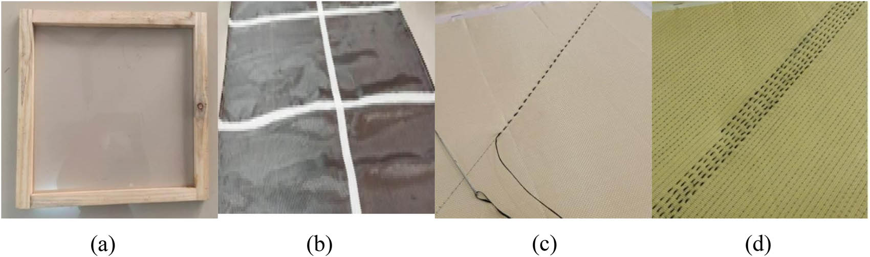
(a) Wooden frame. (b) 2D fabric marked to cut for the dimensions of wooden frame. (c) Woven binder yarn in the diagonal direction. (d) Uniformly spaced binder yarn in the fabric.
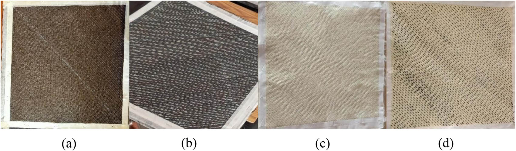
Woven (a) CCC, (b) CCK, (c) KKK, and (d) KKC fabrics.
A mixture of Araldite LY 556 resin and HY 951 hardener was prepared by carefully maintaining the weight ratio as ten parts of resin to one part of hardener. The prepared mixture was then applied over the woven fabric to attain the uniform wetting of fibers. The matrix applied woven fabric was then vacuum bagged under a vacuum pressure of 25 mmHg to get a quality laminate. During vacuum bagging, the vacuum pump was turned on for 6 h, after which the pump was turned off and left for 48 h to remove the excess resin and air bubbles.
The prepared laminates were cut into specimens as per ASTM standards and tested for tensile strength, flexural strength, and impact loadings. Further, fracture response was also determined through mode-I loading.
2.1 Specimens and experimentation
Tensile coupons were prepared as per the ASTM standard D3039, which determines the in-plane tensile properties of polymer matrix composites. The specimen had dimensions of 25 mm in width, 250 mm in length, and constant thickness. The total length was equal to the combination of total gripping length (100 mm) and gauge length (150 mm) as per the standard. The grips were aligned properly to reduce the bending effects.
Flexural specimens were prepared as per the ASTM standard D790 with rectangular cross-sectional dimensions of 25 mm in width, 150 mm in length, and constant thickness. The total length was equal to the combination of total gripping length (20 mm) and gauge length (130 mm) as per the standard.
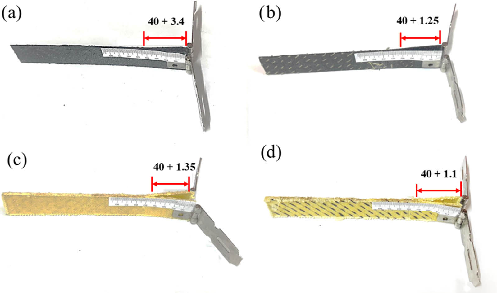
In the fracture toughness test, the objective was to determine the material’s resistance to fracture and its ability to withstand crack propagation. The geometry of a typical DCB specimen used in this work was according to ASTM D5528, in which h is the specimen thickness (which was varied), a 0 is the initial crack if any, a is the length of any propagating crack, d is the crack opening as forced by the wedge forces applied at P, and δ* is the crack opening at the tip of the original notch. Details of the loading and measurement methods are that the total length of the pre-cracked specimen was 150 mm. During the test, a pre-cracked (a 0 = 40) specimen was subjected to a controlled loading, typically in a tension or bending configuration. The applied load gradually increased and allowed the crack to propagate. The displacement ‘δ’ is the full opening point due to the application of load P. The critical strain energy release rate (G IC) was calculated from the fracture data of composite DCB specimens following Eq. (2).
Details of the loading and measurement method are provided in Section 2. The beam was loaded at the end with a force perpendicular to the longitudinal axis of the specimen, which is the standard configuration of the DCB test. The relationship between the load P, opening displacement δ, and crack length was determined using the simple beam theory (SBT), which is expressed as follows:
The energy release rate is derived as follows:
Evaluation of the critical load and the associated critical deflection of the cantilever section was done by Eqs. (3) and (4).
Here, P
cr and
The maximum load applied during the DCB test of a material with a known modulus E and applied value of G IC may be evaluated as follows:
For mode-I interlaminar fracture toughness, four distinct composite laminates were considered: CCC, KKK, CCK, and KKC with a pre crack length of a 0 = 40 mm. The pre-crack length value was used to evaluate the last stage of delamination of the laminates, allowing for the determination of the maximum energy absorbed during the fracture. Load–deflection curves were obtained by testing.
The impact test was conducted to evaluate the material’s ability to withstand sudden impact. It measures the material’s resistance to fracture and deformation under high-energy impact conditions. This test provides important information about the material’s impact strength. In an impact test, a standardized specimen was subjected to a sudden impact from a falling weight. The impact energy was transferred to the specimen, causing deformation, damage, and sometimes fracture. The dimensions of the test specimen were 150 mm (length) × 100 mm (width) × 4.5 mm (thickness). The prepared specimens for tensile, flexure, fracture toughness, and impact testing using the vacuum bagging process are shown in Figure 3.
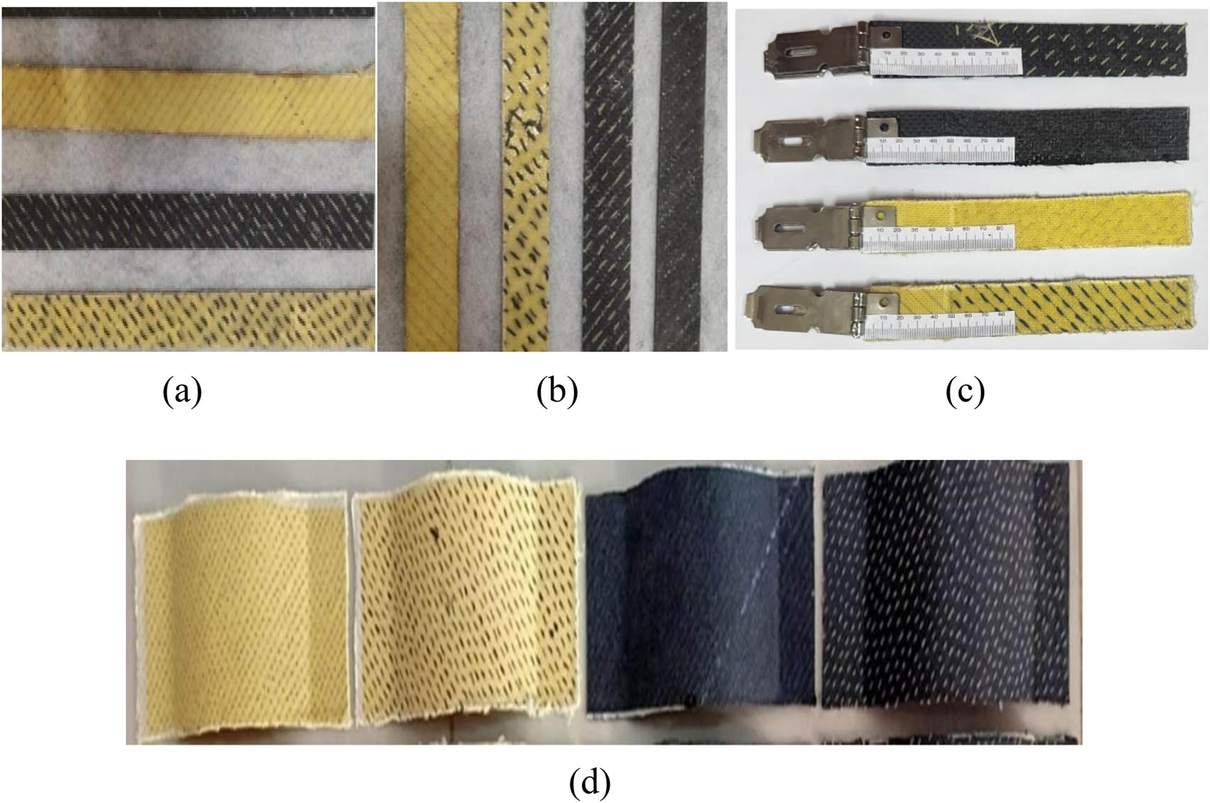
Prepared specimens for the (a) tensile test, (b) flexural test, (c) fracture toughness test, and (d) impact test.
The experimental setup for tensile, flexure, impact, and fracture toughness testing is shown in Figure 4, and the correspondingly tested specimens for tensile, flexure, and impact tests are shown in Figure 5.
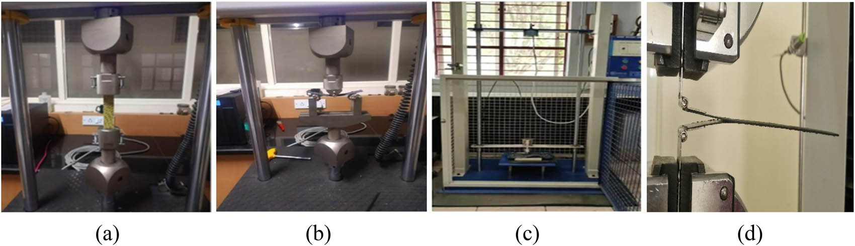
Experimental setup for the (a) tensile test, (b) flexural test, (c) impact rest, and (d) fracture toughness test.
Tested specimens of the (a) tensile test, (b) flexural test, and (c) impact test.
3 Results and discussion
3.1 Tensile testing
Testing was conducted at room temperature with a constant rate of 1.2 mm/min, as shown in Figure 5(a). Five specimens were tested for each case, and the average response is shown in Figure 6. From the engineering stress–strain curve, it is clear that the presence of Kevlar increased the strain, and the increment was higher when the Kevlar fibers were placed in the in-plane loading direction. It is noticed that the failure strain of the KKK specimen was 153, 115, and 31% higher than those of CCC, CCK, and KKC specimens, respectively. Failure stress is noticed to be superior in the case of CCK and KKK composites compared to KKC and CCC composites. The presence of Kevlar yarns as a binder increased the peak stress, and a greater response is noticed in the hybrid composites than others with the same binder. The peak stress of the CCK composite is 1.1, 20.5, and 46.6% higher than those of KKK, KKC, and CCC composites, respectively. The stiffness of the specimens improved by the presence of carbon yarns except in the case of CCC composite, and it is higher in the hybrid specimens. CCK showed stiffness that is 22, 82.8, and 105% higher than those of CCC, KKC, and KKK specimens, respectively. It is also noticed that the presence of Kevlar contributes to higher specific strength, and the effect is higher when the Kevlar yarns are placed as a binder. KKK specimens resulted in 28.8, 45, and 86% higher strength to weight ratio than CCK, KKC, and CCC specimens, respectively. Among the combinations provided, the CCK specimen results in better tensile modulus and peak stress with a moderate strength to weight ratio, as given in Table 2.
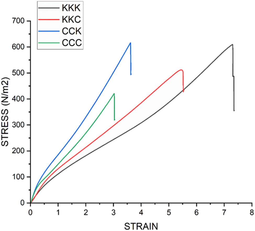
Tensile response of woven composites.
Tensile behavior of woven composites
| Specimen | Tensile modulus in GPa | Peak stress in MPa | Strength to weight ratio |
|---|---|---|---|
| CCC | 139.157 | 420.899 | 50.347 |
| CCK | 170.509 | 616.482 | 72.784 |
| KKC | 93.359 | 511.104 | 64.615 |
| KKK | 83.477 | 609.679 | 93.797 |
3.2 Flexural testing
The loading test was done in a universal testing machine with a crosshead movement of 1.0 mm/min, and the three-point bending setup and tested specimens are shown in Figures 4(b) and 5(b), respectively. The stress–strain responses for four distinct combinations of 3D woven carbon and Kevlar materials were recorded. Each combination underwent five separate flexural tests, and the resulting data from these tests were averaged for each combination, as shown in Figure 7 and Table 3. The objective of this graph is to facilitate a comparative analysis of the combinations and determine which exhibits the best flexural strength among them.
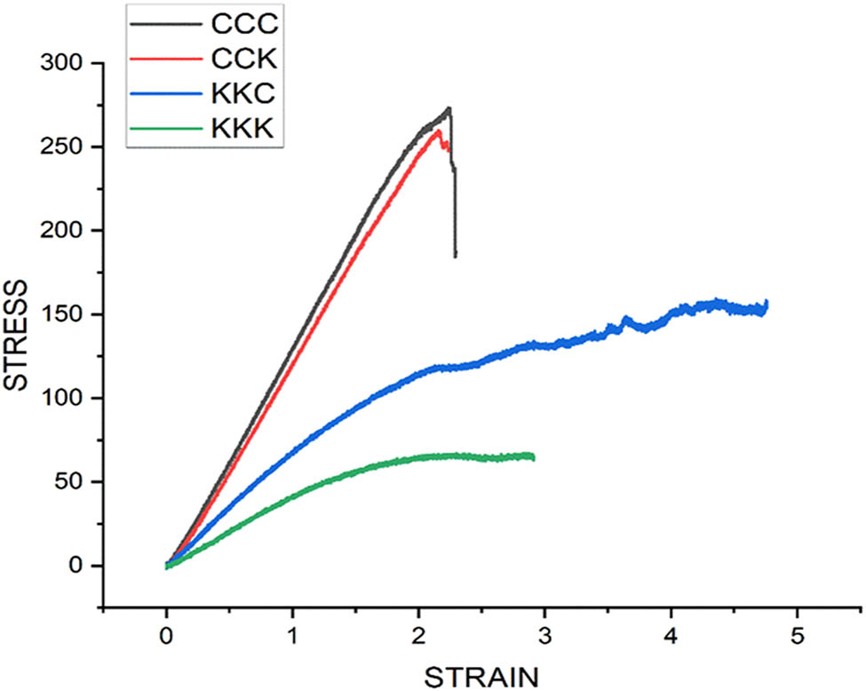
Flexural response of woven composites.
Flexural test strength to weight ratio
| Specimen | Average peak stress (MPa) | Weight (g) | Strength to weight ratio |
|---|---|---|---|
| CCC | 273.443 | 8.36 | 32.708 |
| CCK | 259.777 | 8.47 | 30.670 |
| KKC | 144.183 | 7.91 | 18.228 |
| KKK | 67.244 | 6.50 | 10.345 |
From the analysis of the provided graph and data concerning Young’s modulus, it can be concluded that the CCC combination exhibits the most favorable characteristics among the tested combinations in terms of strain reduction and stress levels. Specifically, the CCC combination experiences the least amount of strain while demonstrating higher stress levels compared to other combinations. This conclusion is drawn by examining the stress–strain curves and considering the Young’s modulus values associated with each combination. The observed lower strain values in the CCC combination suggest its ability to withstand deformation or elongation to a lesser extent, while the higher stress values indicate its capacity to handle greater applied forces.
3.3 Fracture toughness testing
Fracture toughness testing is a mechanical test method used to determine the energy needed to initiate and cause failure within a material. The tested specimens and obtained graphs are depicted in Figures 8 and 9, respectively. Figure 9 illustrates the load–displacement curves for four distinct combinations of 3D woven carbon and Kevlar materials. Each combination underwent five separate fracture toughness tests.
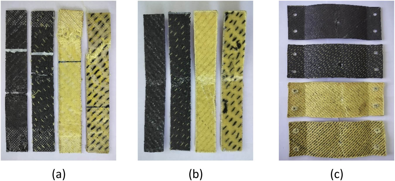
Tested specimens of the fracture toughness test: (a) CCC, (b) CCK, (c) KKK, and (d) KKC.
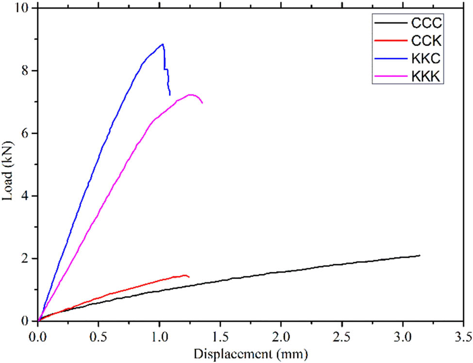
Mode-I delamination response of woven composites.
The mode-I critical strain energy release rates are determined by using the double cantilever beam method. It is found that GIC dramatically increases due to stitching. We could conclude that the 3D woven KKC hybrid laminate has greater fracture toughness than CCK, KKK, and CCC because carbon has a higher tensile strength than Kevlar. Figure 10 shows the variation of critical strain energy release rate with crack length.
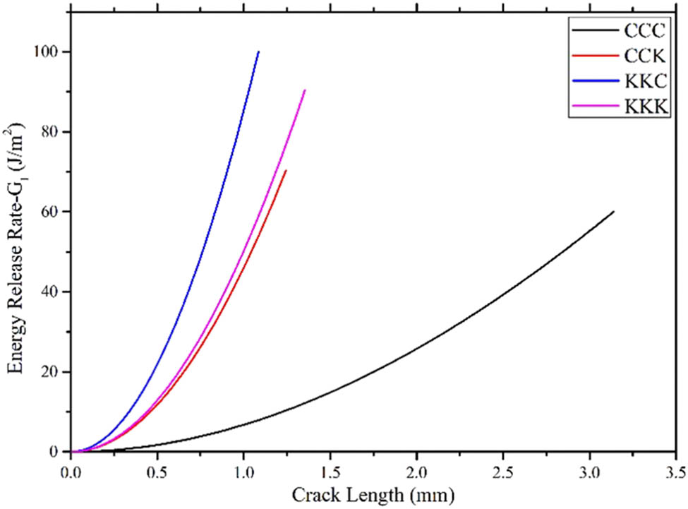
Mode-I critical strain energy release rate of 3D woven composites.
The load and deflection at specific crack lengths for CCC, CCK, KKK, and KKC samples are tabulated in Table 4. The synergistic effect of fibers, effective interfacial bonding, and favorable material properties for KKC combination is shown in Figure 10. These factors contribute to the enhanced ability of the composite to withstand crack propagation, making it the best combination in terms of fracture toughness.
Crack length, load, and deflection for different samples
| CCC | CCK | KKK | KKC | ||||||||
|---|---|---|---|---|---|---|---|---|---|---|---|
| Crack length, a 0 + a 1 (mm) | Load (kN) | Deflec-tion, δ (mm) | Crack length, a 0 + a 1 (mm) | Load (kN) | Deflec-tion, δ (mm) | Crack length, a 0 + a 1 (mm) | Load (kN) | Deflec-tion, δ (mm) | Crack length, a 0 + a 1 (mm) | Load (kN) | Deflec-tion, δ (mm) |
| 40 | 0 | 4.8 | 40 | 0 | 6.45 | 40 | 0 | 8.4 | 40 | 0 | 7.2 |
| 40.5 | 0.592 | 5.1 | 40.25 | 0.395 | 6.9 | 40.25 | 2.723 | 8.7 | 40.2 | 1.405 | 7.6 |
| 41 | 0.971 | 5.4 | 40.5 | 0.761 | 7.5 | 40.5 | 5.212 | 9.3 | 40.5 | 3.455 | 8.1 |
| 41.5 | 1.36 | 5.7 | 40.75 | 1.039 | 7.9 | 40.75 | 7.408 | 9.8 | 40.9 | 6.163 | 8.6 |
| 42 | 1.572 | 6.2 | 41 | 1.317 | 8.4 | 41.15 | 8.579 | 10.3 | 41 | 6.617 | 9.08 |
| 42.5 | 1.827 | 68 | 41.15 | 1.42 | 8.7 | 41.25 | 8.038 | 10.5 | 41.08 | 6.852 | 9.6 |
| 43 | 2.041 | 7.3 | 41.25 | 1.405 | 9.12 | 41.35 | 7.218 | 10.9 | 41.1 | 7.086 | 10.5 |
The obtained average results for the peak stress and strength to weight ratio of fracture toughness test are shown in Table 5. Up to the maximum load point, when fracture development propagation is steady, load variations are seen to be linear. Following this, there is a sharp decline in load until it reaches a certain amount, at which time it starts to drop as quickly as an unstable fracture, where critical load and deflection are obtained. The average maximum load values for various composites are shown in Figure 9, which displays the resistance to the fracture curve (R-curve) for mode-I. The fiber bridging phenomena, matrix cracking, tow breaking, multiple delamination, and tow bridging in the case of woven fiber composites have an impact on the R-curve’s form. Consistent crack development is observed, although only a little load drop is seen right after the first crack commencement as the displacement is increased.
Fracture toughness strength to weight ratio
| Specimen | Average peak stress (MPa) | Weight (g) | Strength to weight ratio |
|---|---|---|---|
| CCC | 2.110 | 6.17 | 0.342 |
| CCK | 2.397 | 6.38 | 0.376 |
| KKC | 8.855 | 6.22 | 1.424 |
| KKK | 7.228 | 5.84 | 1.238 |
3.4 Impact testing
The impact test was conducted to study the ability of a material to withstand impact. The obtained results for average absorbed energy, displacement, and impact force of different specimens are shown in Table 6.
Average of absorbed energy, displacement, and impact force of CCC, CCK, KKC, and KKK samples
| Samples | Absorbed energy (J) | Displacement (mm) | Impact force (N) |
|---|---|---|---|
| CCC | 19.98 | 10.038 | 1.99 |
| CCK | 15.52 | 10.204 | 1.522 |
| KKC | 20.1 | 11.04 | 1.828 |
| KKK | 22.22 | 9.426 | 2.444 |
In the impact test, the KKK combination emerges as the most favorable choice among the tested combinations, displaying the highest absorbed energy (22.22 J), during the impact test, and this combination offers excellent impact resistance and energy absorption capabilities.
4 Conclusions
The CCK combination stands out as the optimal choice among the tested combinations in terms of tensile modulus, making it well suited for aeronautical applications that require high tensile strength and stiffness. In the CCK combination, the presence of Kevlar fibers in the Z direction plays a crucial role in distributing stress and helps to prevent the formation and propagation of cracks or fractures within the material. The CCC combination emerges as the most favorable choice among the tested combinations, demonstrating the highest Young’s modulus for flexural strength for excellent resistance to bending.
The KKC combination emerges as the most favorable choice among the tested combinations, with the highest fracture toughness, and this combination exhibits exceptional resistance to crack propagation and improved durability. In the KKC combination, the presence of carbon fibers in the Z direction plays a crucial role in enhancing the fracture toughness and preventing crack propagation when the material is under tensile load during the fracture toughness test.
The presence of Kevlar fibers in all layers of the composite structure contributes to its remarkable impact resistance. When subjected to an impact, the Kevlar fibers effectively distribute and absorb the energy generated by the impact, preventing it from propagating and causing significant damage to the structure. This ability to absorb and dissipate impact energy ensures the integrity and durability of the aeronautical components, even under high-stress conditions.
In future, the researchers can extend this work to analyze the effect of different binder yarn angles and material variation on the fracture toughness and impact resistance.
Acknowledgments
The authors would like to express their gratitude to Hindustan Institute of Technology and Science for providing the resources and facilities necessary for conducting this research. Additionally, they extend their sincere thanks to the research center at NITTE Institute of Technology for their invaluable support and expertise throughout the experiment. Their contributions played a crucial role in successful completion of this study.
-
Funding information: The authors state that no funding was involved.
-
Author contributions: Ram Vishal: writing – original draft, investigation, and editing; Shubha: review; Sambhaji: methodology. All authors have accepted responsibility for the entire content of this manuscript and approved its submission.
-
Conflict of interest: The authors declare that they have no conflicts of interest.
-
Data availability statement: Data sharing is not applicable to this article as no datasets were generated or analyzed during the current study.
References
[1] Samouh Z, Abed A, Cherkaoui O, Soulat D, Labanieh AR, Boussu F, et al. Investigation on the properties of 3D warp interlock fabrics based on Moroccan sisal yarns as reinforcement for composite materials. J Nat Fibers. 2022;19:6822–40.10.1080/15440478.2021.1932679Search in Google Scholar
[2] Patti A, Acierno D. Materials, weaving parameters, and tensile responses of woven textiles. Macromol. 2023;3(3):665–80.10.3390/macromol3030037Search in Google Scholar
[3] Abtew MA, Boussu F, Bruniaux P, Liu H. Fabrication and mechanical characterization of dry three-dimensional warp interlock para-aramid woven fabrics: Experimental methods toward applications in composite reinforcement and soft body armor. Materials (Basel). 2020;13(19):4233.10.3390/ma13194233Search in Google Scholar PubMed PubMed Central
[4] McClain M, Goering J. Overview of recent developments in 3D structures. Albany Eng Compos. 2012;4(2):1–12.Search in Google Scholar
[5] Shi X, Sun Y, Xu J, Chen L, Zhang C, Zhang G. Effect of fiber fraction on ballistic impact behavior of 3D woven composites. Polymers. 2023;15(5):1170.10.3390/polym15051170Search in Google Scholar PubMed PubMed Central
[6] Perera YS, Muwanwella RMHW, Fernando PR, Fernando SK, Jayawardana TSS. Evolution of 3D weaving and 3D woven fabric structures. Fash Text. 2021;8(11):1–11.10.1186/s40691-020-00240-7Search in Google Scholar
[7] El-Dessouky HM, Saleh MN. 3D woven composites: From weaving to manufacturing Recent Developments in the Field of Carbon Fibers. London, United Kingdom: IntechOpen; 2018. p. 51–66.10.5772/intechopen.74311Search in Google Scholar
[8] Jayan VR, Tripathi L, Behera PK, Petru M, Behera B. Prediction of internal geometry and tensile behavior of 3D woven solid structures by mathematical coding. J Ind Text. 2022;51(4):7034–55.10.1177/15280837211001348Search in Google Scholar
[9] Sun J, Dai Y, Huang L, Zhao J. Failure assessment of 3D woven composites under compression after low-velocity impact. Mater Res Express. 2022;9(10):105301.10.1088/2053-1591/ac94b7Search in Google Scholar
[10] Saleh MN, Yudhanto A, Potluri P, Lubineau G, Soutis C. Characterising the loading direction sensitivity of 3D woven composites: Effect of z-binder architecture. Compos Part A: Appl Sci Manuf. 2016;90:577–88.10.1016/j.compositesa.2016.08.028Search in Google Scholar
[11] Stig F, Hallström S. Influence of crimp on 3D-woven fiber reinforced composites. Compos Struct. 2013;95:114–22.10.1016/j.compstruct.2012.07.022Search in Google Scholar
[12] Saleh MN, Soutis C. Recent advancements in mechanical characterisation of 3D woven composites. Mech Adv Mater Mod Process. 2017;3:1–7.10.1186/s40759-017-0027-zSearch in Google Scholar
[13] Tan P, Tong L, Steven GP, Ishikawa T. Behavior of 3D orthogonal woven CFRP composites. Part I. Experimental investigation. Compos Part A: Appl Sci Manuf. 2000;31(3):259–71.10.1016/S1359-835X(99)00070-6Search in Google Scholar
[14] Quinn JP, McIlhagger AT, McIlhagger R. Examination of the failure of 3D woven composites. Compos Part A: Appl Sci Manuf. 2008;39(2):273–83.10.1016/j.compositesa.2007.10.012Search in Google Scholar
[15] Yu YM, Wang XJ, Lim CW. Ballistic impact of 3D orthogonal woven composite by a spherical bullet: experimental study and numerical simulation. Int J Eng Appl Sci. 2009;1(1):1–8.Search in Google Scholar
[16] Gu H, Zhili Z. Tensile behavior of 3D woven composites by using different fabric structures. Mater & Des. 2002;23(7):671–4.10.1016/S0261-3069(02)00053-5Search in Google Scholar
[17] Brandt J, Drechsler K, Arendts FJ. Mechanical performance of composites based on various three-dimensional woven-fiber preforms. Compos Sci Technol. 1996;56(3):381–6.10.1016/0266-3538(95)00135-2Search in Google Scholar
[18] Cai-yun YA, Jia-lu LI, Guo-li ZH. Study of relationship between structures and mechanical properties of three-dimensional angle-interlock woven carbon/resin composites. J Aeronaut Mater. 2006;26(5):51–5.Search in Google Scholar
[19] Chen X, Spola M, Paya JG, Sellabona1 PM. Experimental studies on the structure and mechanical properties of multi-layer and angle-interlock woven structures. J Text Inst. 1999;90(1):91–9.10.1080/00405009908658693Search in Google Scholar
[20] Sun F, Sun Y, Zhang Q, Zhang D, Chen L. Experimental investigation on bending behavior of 3D non-crimp orthogonal composite. J Rein Plast Compos. 2014;33(20):1869–78.10.1177/0731684414548609Search in Google Scholar
[21] Jin L, Niu Z, Jin BC, Sun B, Gu B. Comparisons of static bending and fatigue damage between 3D angle-interlock and 3D orthogonal woven composites. J Rein Plast Compos. 2012;31(14):935–45.10.1177/0731684412450626Search in Google Scholar
[22] Dai S, Cunningham PR, Marshall S, Silva C. Influence of fiber architecture on the tensile, compressive and flexural behaviour of 3D woven composites. Compos Part A: Appl Sci Manuf. 2015;69:195–207.10.1016/j.compositesa.2014.11.012Search in Google Scholar
[23] Guenon VAF. Interlaminar fracture toughness of a three-dimensional composite. Master Thesis of Applied Science in Mechanical Engineering. Newark: University of Delaware; 1987.Search in Google Scholar
[24] Tanzawa Y, Watanabe N, Ishikawa T. Interlaminar fracture toughness of 3-D orthogonal interlocked fabric composites. Compos Sci Technol. 1999;59(8):1261–70.10.1016/S0266-3538(98)00167-5Search in Google Scholar
[25] Mouritz AP, Baini C, Herszberg I. Mode I interlaminar fracture toughness properties of advanced textile fibreglass composites. Compos Part A: Appl Sci Manuf. 1999;30(7):859–70.10.1016/S1359-835X(98)00197-3Search in Google Scholar
[26] Fishpool DT, Rezai A, Baker D, Ogin SL, Smith PA. Interlaminar toughness characterisation of 3D woven carbon fiber composites. Plastics Rubber Compos. 2013;42(3):108–14.10.1179/1743289812Y.0000000036Search in Google Scholar
[27] Saleh MN, El-Dessouky HM, Saeedifar M, De Freitas ST, Scaife RJ, Zarouchas D. Compression after multiple low velocity impacts of NCF, 2D and 3D woven composites. Compos Part A: Appl Sci Manuf. 2019;125:105576.10.1016/j.compositesa.2019.105576Search in Google Scholar
[28] Kazemianfar B, Esmaeeli M, Nami MR. Experimental investigation on response and failure modes of 2D and 3D woven composites under low velocity impact. J Mater Sci. 2020;55(3):1069–91.10.1007/s10853-019-04096-1Search in Google Scholar
[29] Seltzer R, González C, Muñoz R, Llorca J, Blanco-Varela T. X-ray microtomography analysis of the damage micromechanisms in 3D woven composites under low-velocity impact. Compos Part A: Appl Sci Manuf. 2013;45:49–60.10.1016/j.compositesa.2012.09.017Search in Google Scholar
[30] Hart KR, Chia PX, Sheridan LE, Wetzel ED, Sottos NR, White SR. Mechanisms and characterization of impact damage in 2D and 3D woven fiber-reinforced composites. Compos Part A: Appl Sci Manuf. 2017;101:432–43.10.1016/j.compositesa.2017.07.004Search in Google Scholar
[31] Kazemianfar B, Esmaeeli M, Nami MR. Response of 3D woven composites under low velocity impact with different impactor geometries. Aerosp Sci Technol. 2020;102:105849.10.1016/j.ast.2020.105849Search in Google Scholar
[32] Nicholls DJ, Gallagher JP. Determination of GIC in angle-ply composites using a cantilever beam test method. J Reinf Plast Compos. 1983;2:2–17.10.1177/073168448300200101Search in Google Scholar
[33] Chai H. The characterization of mode I delamination failure in nonwoven, multidirectional laminates. Composites. 1984;15:277–90.10.1016/0010-4361(84)90708-0Search in Google Scholar
[34] Laksimi A, Benzeggagh ML, Jing G, Hecini M, Roelandt JM. Mode I inter-laminar fracture of symmetrical cross-ply composites. Compos Sci Technol. 1991;41:147–64.10.1016/0266-3538(91)90025-KSearch in Google Scholar
[35] Robinson P, Song DQ. A modified DCB specimen for mode-I testing of multidirectional laminates. J Compos Mater. 1992;26:1554–77.10.1177/002199839202601101Search in Google Scholar
© 2025 the author(s), published by De Gruyter
This work is licensed under the Creative Commons Attribution 4.0 International License.
Articles in the same Issue
- Research Articles
- Probing microstructural evolution and surface hardening of AISI D3 steel after multistage heat treatment: An experimental and numerical analysis
- Activation energy of lime cement containing pozzolanic materials
- Optimizing surface quality in PMEDM using SiC powder material by combined solution response surface methodology – Adaptive neuro fuzzy inference system
- Experimental study of the mechanical shear behaviour of steel rebar connectors in timber–concrete structure with leafy wood species
- Development of structural grade lightweight geopolymer concrete using eco-friendly materials
- An experimental approach for the determination of the physical and mechanical properties of a sustainable geopolymer mortar made with Algerian ground-granulated blast furnace slag
- Effect of using different backing plate materials in autogenous TIG welding on bead geometry, microhardness, tensile strength, and fracture of 1020 low carbon steel
- Uncertainty analysis of bending response of flexoelectric nanocomposite plate
- Leveraging normal distribution and fuzzy S-function approaches for solar cell electrical characteristic optimization
- Effect of medium-density fiberboard sawdust content on the dynamic and mechanical properties of epoxy-based composite
- Mechanical properties of high-strength cement mortar including silica fume and reinforced with single and hybrid fibers
- Study the effective factors on the industrial hardfacing for low carbon steel based on Taguchi method
- Analysis of the combined effects of preheating and welding wire feed rates on the FCAW bead geometric characteristics of 1020 steel using fuzzy logic-based prediction models
- Effect of partially replacing crushed oyster shell as fine aggregate on the shear behavior of short RC beams using GFRP rebar strengthened with TRC: Experimental and numerical studies
- Micromechanic models for manufacturing quality prediction of cantula fiber-reinforced nHA/magnesium/shellac as biomaterial composites
- Numerical simulations of the influence of thermal cycling parameters on the mechanical response of SAC305 interconnects
- Impact of nanoparticles on the performance of metakaolin-based geopolymer composites
- Enhancing mechanical and thermal properties of epoxy-based polymer matrix composites through hybrid reinforcement with carbon, glass and steel
- Prevention of crack kinetic development in a damaged rod exposed to an aggressive environment
- Ideal strain gauge location for evaluating stress intensity factor in edge-cracked aluminum plates
- Experimental and multiscale numerical analysis of elastic mechanical properties and failure in woven fabric E-glass/polyester composites
- Optimizing piezoelectric patch placement for active repair of center-cracked plates
- Experimental investigation on the transverse crushing performance of 3D printed polymer composite filled aluminium tubes
- Review Articles
- Advancing asphaltic rail tracks: Bridging knowledge gaps and challenges for sustainable railway infrastructure
- Chemical stabilization techniques for clay soil: A comprehensive review
- Development and current milestone of train braking system based on failure phenomenon and accident case
- Rapid Communication
- The role of turbulence in bottom-up nanoparticle synthesis using ultrafast laser filamentation in ethanol
- Special Issue on Deformation and Fracture of Advanced High Temperature Materials - Part II
- Effect of parameters on thermal stress in transpiration cooling of leading-edge with layered gradient
- Development of a piezo actuator-based fatigue testing machine for miniature specimens and validation of size effects on fatigue properties
- Development of a 1,000°C class creep testing machine for ultraminiature specimens and feasibility verification
- Special Issue on Advances in Processing, Characterization and Sustainability of Modern Materials - Part II
- Surface integrity studies in microhole drilling of Titanium Beta-C alloy using microEDM
- Experimental investigation on bacterial concrete by using Cantabro loss and UPV
- Influence of gas nitriding on the surface layer of M50 NiL steel for aerospace-bearing applications
- Experimental investigation on the spectral, mechanical, and thermal behaviors of thermoplastic starch and de-laminated talc-filled sustainable bio-nanocomposite of polypropylene
- Synthesis and characterization of sustainable hybrid bio-nanocomposite of starch and polypropylene for electrical engineering applications
- Microstructural and mechanical characterization of Al6061-ZrB2 nanocomposites fabricated by powder metallurgy
- Effect of edge preparation on hardness and corrosion behaviour of AA6061-T651 friction stir welds
- Mechanical improvement in acetal composites reinforced with graphene nanotubes and Teflon fibers using loss functions
- Experimental investigation on the mechanical properties of aluminum-based metal matrix composites by the squeeze casting method
- Investigation on punch force–displacement and thickness changes in the shallow drawing of AA2014 aluminium alloy sheets using finite element simulations
- Influence of liquid nitriding on the surface layer of M50 NiL steel for bearing applications
- Mechanical and tribological analyses of Al6061-GO/CNT hybrid nanocomposites by combined vacuum-assisted and ultrasonicated stir casting method
- Strengthening of structures with bacterial concrete for effective crack repair and durability enhancement
- Unique approaches in developing novel nano-composites: Evaluating their mechanical and tribological characteristics
- Load-carrying capacity of highly compact rigid deployable booms
- Investigating the influence of SiC and B4C reinforcements on the mechanical and microstructural properties of stir-casted magnesium hybrid composites
- Evaluation of mechanical and performance characteristics of bitumen mixture using waste septage ash as partial substitute
- Mechanical characterization of carbon/Kevlar hybrid woven 3D composites
- Development of a 3D-printed cervical collar using biocompatible and sustainable polylactic acid
- Mechanical characterization of walnut shell powder-reinforced neem shell liquid composite
- Special Issue on Structure-energy Collaboration towards Sustainability Societies
- Effect of tunneling conductivity of CNTs on the EMI shielding effectiveness of nanocomposite in the C-band
- Evaluation of the effect of material selection and core geometry in thin-walled sandwich structures due to compressive strength using a finite element method
- Special Issue on Sustainability and Development in Civil Engineering - Part III
- The optimum reinforcement length for ring footing resting on sandy soils resisting inclined load
- Special Issue on Advanced Materials in Industry 4.0
- Cross-dataset evaluation of deep learning models for crack classification in structural surfaces
- Mechanical and antibacterial characteristics of a 3D-printed nano-titanium dioxide–hydroxyapatite dental resin-based composite