Comparative study between dry and wet properties of thermoplastic PA6/PP novel matrix-based carbon fibre composites
-
Aparna Sridhar
 ,
Purnima Doddipatla
,
Purnima Doddipatla

Abstract
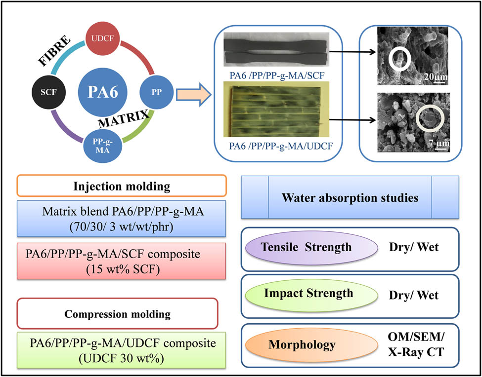
The aim of the study is to develop and investigate the suitability of thermoplastic composites for underwater applications. PA6/PP/PP-g-MA (70 wt%/30 wt%/3 phr) blend is used as a novel matrix to synthesize UDCF composites with balanced strength and toughness even in humid conditions. This novel matrix has around 60% lower water absorption capacity compared to PA6. Short carbon fibres (SCF) and unidirectional carbon fibre fabric (UDCF with 12K rovings) are used as reinforcements. X-ray CT data of injection-molded SCF composites revealed good wetting. However, in the case of compression-molded UDCF composites, a few unwetted zones were found. Comparing dry and wet samples, wet-matrix, wet-SCF composite and wet-UDCF composites had 40, 15, and 25% reduction in their tensile strengths, respectively. However, the impact strength of wet-matrix and wet-UDCF composites increased by 67 and 61%, respectively. Hence, SCF composites having a wet tensile strength of 46 MPa can be used in preparing underwater components due to the low number of interfacial voids. UDCF composites having more interfacial voids are recommended for humid conditions wherein the wet impact strength (11.4 J) and wet tensile strength (266 MPa) are the main criteria.
Graphical abstract
1 Introduction
Carbon-fibre-reinforced polymer (CFRP) composites are widely preferred to metals due to their high specific strength, stiffness and corrosion resistance, especially in aerospace and marine applications. Thermoplastic matrices like polypropylene (PP), polyamide 6 (PA6) and polyetherether ketone (PEEK) are gaining interest over traditional thermoset matrices because of their recyclability and processing flexibilities such as extrusion and injection molding. The major drawback of PA6 is its affinity towards moisture due to the polar groups present in its chain. From our earlier study, it was observed experimentally that PA6 absorbs ∼6.3 wt% of water, which in turn causes a ∼37% reduction in the tensile strength [1].
To overcome the hydrophilicity of PA6, the hydrophobic polymer “PP” was blended with PA6 to prepare the PA6/PP matrix blend [1,2,3,4,5,6]. Since PP is immiscible with PA6, PP-g-MA was chosen as a compatibilizer. From our earlier study of optimization of the matrix blend [4], it was concluded that compatibilized blends (PA6/PP/PP-g-MA) at 30 wt% PP content had the lowest water absorption (1.5%) and higher yield strength in wet conditions. The impact strength of the matrix blend at 30 wt% PP content was also higher owing to a better PP/PP-g-MA ratio and the optimum domain size distribution of PP (0.82 µm) in the PA6 phase. Since PA6/PP/PP-g-MA (70/30/3 wt/wt/phr) had balanced mechanical properties with low water absorption capacity, this ternary blend was chosen as a novel matrix blend for the composite preparation [5]. Extensive studies were reported on PA6/glass fibre composites and PA6/SCF (short carbon fibre) composites [7,8,9,10]. But, very few studies were carried out using PA6 blend as a thermoplastic matrix and carbon or glass fibres as reinforcement [11,12,13,14], and no comparison of properties was reported among matrix, SCF composites, and unidirectional carbon fibre fabric (UDCF) composites, especially after saturating with water.
In one study, the mechanical properties of the PA6/SCF composites prepared with 2, 4, 6, 8 and 20 wt% SCF reinforcement were compared, and it was found that the tensile strength and tensile modulus increase with the increase in the SCF content, wherein the maximum fibres had a residual length of 50 µm [7]. Long fibre-based thermoplastic composites were made using the prepreg technique, i.e. impregnation of fibre roving with matrix or the powder coating of matrix followed by heating, but very few studies were reported on the film stacking (compression molding) technique, which is easy to adopt for bulk manufacturing [15]. In one study, 200 µm thin “blow-molded PA6” sheets were used to prepare UDCF composites. They found that the tensile strength increased with an increase in the fibre volume fraction, which could be due to a fewer voids and good interfacial adhesion [15]. A few studies were focused on the Izod impact testing of SCF composites [8,9] and the low-velocity impact (LVI) testing of UDCF composites [16,17,18], but no comparison between novel matrix blend and composites was reported.
A few studies have dealt with the effect of moisture absorption in thermoset composites [19,20,21,22]. Canale et al. [19] reported 1 wt% of water absorption after saturating the 15 mm thick carbon-epoxy laminate at 70°C and 85% RH for 15,000 h. Rubino et al. [20] summarized the applications of thermoset composites in marine applications like underwater repairs of steel structures, fully composite ships of 80-m length, ducts, pipes and racing powerboats. However, moisture absorption in thermoplastic composites based on long carbon fibres and PA6 thermoplastic matrix are very limited [13,23]. In this study, a short carbon fibre (SCF-15 wt%) and unidirectional carbon fibre fabric (UDCF-30 wt%) are used as reinforcement, and composites were made using injection molding and compression molding, respectively. Water absorption capacity, tensile properties and impact properties of PA6, matrix blend-PA6B (PA6/PP/PP-g-MA 70/30/3 wt/wt/phr), SCF composites (PA6B/15 wt% SCF) and UDCF composites (PA6B/30 wt% UDCF) have been compared. Initially, water absorption of the PA6, matrix blend and composites are compared to check the feasibility of these composites for high humid applications. The tensile strength (dry and wet), impact strength (dry and wet) and tensile modulus (dry and wet) are compared among PA6, matrix blend, SCF composites and UDCF composites to study the influence of the carbon fibre content on wet and dry composite properties. Here, the comparison of the bare matrix with composites has been discussed, as the matrix is a novel thermoplastic blend that has been developed for moisture resistance applications.
2 Materials and methods
2.1 Materials (fibre, matrix, compatibilizer)
PA6 of grade Gujlon M28RC was obtained from Gujarat State Fertilizer & Chemicals Ltd., India and PP of grade Repol H030SG was obtained from Reliance Industries Ltd., India. SCF having an average length of 1 mm and an average diameter of 7 μm with 1 wt% epoxy sizing and UDCF with 1 wt% epoxy sizing was obtained from Sun Young Industry, South Korea. The UDCF carbon fibre rovings (TC35-12K) are held together by stitching to consider it as a fabric, as shown in Figure 1b. PP-g-MA of grade Optim-408 was obtained from Pluss Polymers Limited, India. NBBSA plasticizer was obtained from MIKU Polymers, Vadodara, India. Mechanical properties of the fibre and matrix blend are given in Table 1.
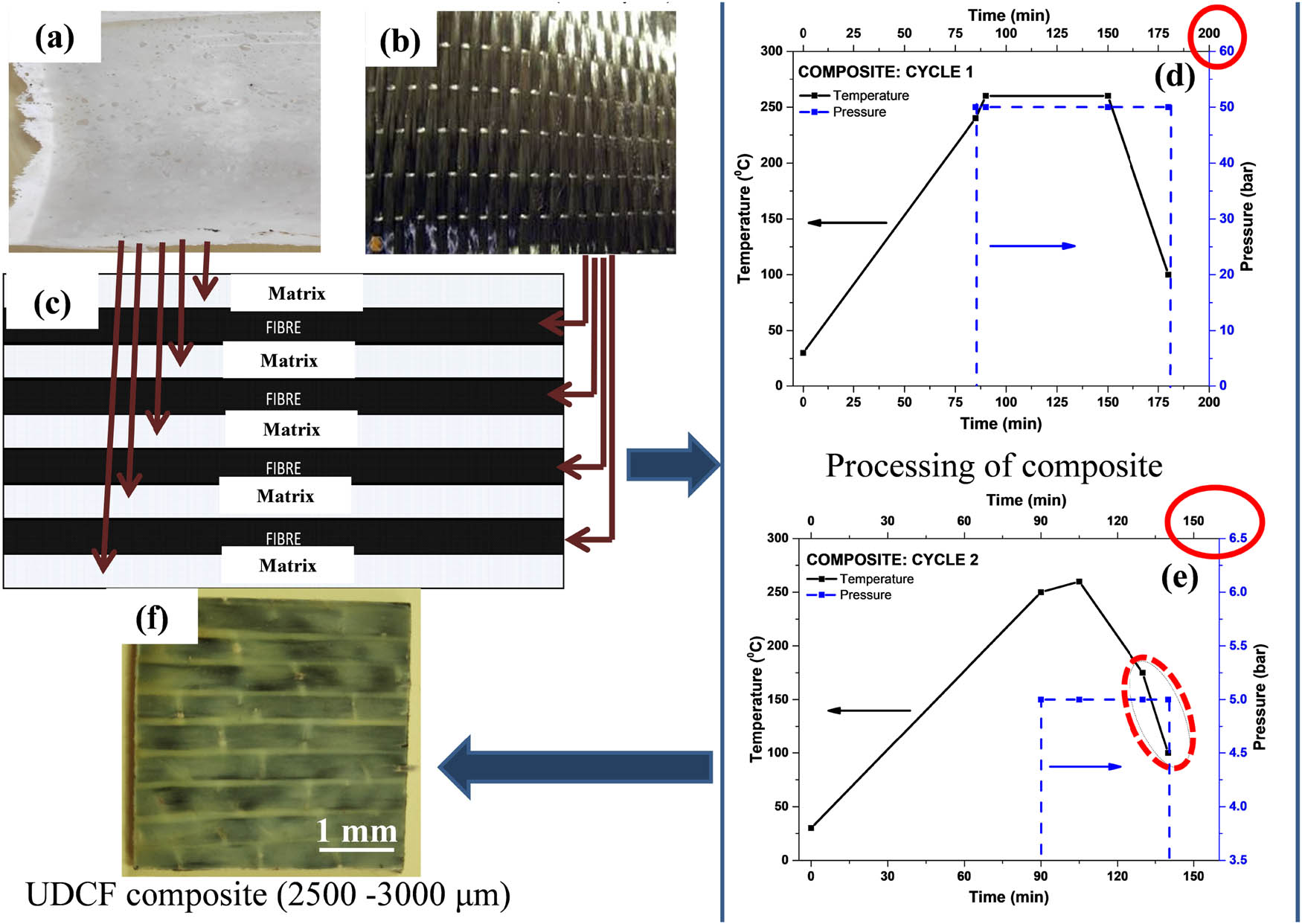
(a) Blend matrix sheet (900 µm thickness), (b) UDCF stitched fabric (120 µm thickness), (c) schematic of the alternate layer of matrix and fibre as arranged in compression molding. Processing of composite (d) cycle-1 and (e) cycle-2 wherein dotted circle represents the water-cooled zone, and (f) final composite specimen of 2.5–3 mm thickness.
Mechanical properties of matrix and fibre
| Material | Tensile strength (MPa) | Tensile modulus (GPa) | Elongation at break (%) |
|---|---|---|---|
| Matrix blend-PA6/PP/PP-g-MA (70/30/3 wt/wt/phr) | 40 | 1.5 | 125 |
| Carbon fibre | 2,200–2,700 | 200–225 | 1.5 |
2.2 Processing of matrix and composites
For processing the novel matrix blend (PA6/PP/PP-g-MA) and SCF-reinforced composites, materials were preheated for 5 h at 80°C in a hot air oven, and then extruded in co-rotating twin-screw extruder. The temperatures of extruder heater zones were set as 170, 180, 190, 210, 220, 230, and 235°C at the die, as shown in Figure 2. The extruded material was cooled in a water bath and pelletized. For preparing the novel matrix blend, PA6 (70 wt%), PP (30 wt%) and PP-g-MA (3 phr) pellets were tumbled and added to the hopper directly. For preparing composites, PA6 + PP + PP-g-MA matrix blend pellets (85 wt%) were added to the hopper, and SCF fibres of 1 mm length (15 wt%) were fed through the feeder located at zone-1. The reactive compatibilization of PP-g-MA with the PA6 end group and the possible reaction between “sizing on SCF” and the PA6 end group have been discussed in our earlier publications [1,5]. The matrix blend pellets or composite pellets obtained from the extrusion process were oven-dried and then injection-molded according to ASTM D638 (tensile specimens) and ASTM D256 (Izod-impact specimens) [1,4,5].
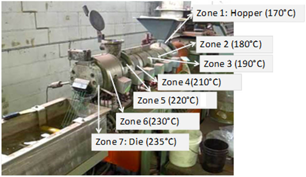
Twin screw extruder used to prepare the novel matrix blend and SCF composites.
The matrix sheet and composite laminates were processed using a compression molding machine (film stacking method) having a size of 20 cm2 × 27 cm2. UDCF composites (PA6/PP/PP-g-MA matrix with ∼30 wt% UDCF fabric as reinforcement) were processed in three stages: (1) processing of 900 µm thick matrix sheets; (2) alternative layers of matrix sheet and UDCF (120 µm) fabric were subjected to compression molding at 260°C and 50 bar pressure to obtain 3–4 mm thick composite laminates; and (3) composite laminates were re-pressed at 260°C and 5 bar pressure to obtain 2.5–3 mm thin composite laminates, as shown in Figure 1.
2.3 Water absorption testing of the PA6 matrix blend and composites
Water absorption tests were carried out as per ASTM D570-98. The tensile and impact specimens of PA6, PA6 matrix blend, SCF composites and UDCF composites were immersed in distilled water (up to a water level of 80%) and weighed every 24 h (Sartorius BSA-423S-CW) until saturation was noticed. It took almost 45 and 20 days, respectively, for the SCF and UDCF composites to fully saturate with water, and mechanical testing was carried out immediately after removing the samples from the water [1,4,5].
2.4 Mechanical testing of the PA6 matrix blend based SCF and UDCF composites
The tensile test was carried out using UTM (Zwick-Roell) at a crosshead speed of 5 mm/min and a gauge length of 50 mm as per ASTM D638 for the matrix blend and SCF composites (165 × 13 gauge width × 3.2 mm3). A tensile test of the UDCF composite laminates was conducted using UTM (ADMET) at a crosshead speed of 1 mm/min and a gauge length of 100 mm as per ASTM D3039. Here, the specimen size was 250 mm3 × 12.5 mm3 × 3 mm3. Tensile properties were studied before (dry) and after water absorption (wet). The percentage of elongation was also measured using the extensometers (SCF composites) and strain gauge (UDCF composites) till the yield point for dry samples. All the tests were carried out at 23–25°C and 50–55% RH.
The notched-Izod impact test was conducted as per ASTM D256 for the matrix blend and SCF composites (CEAST 9050). Flat specimens of 3.2 mm thickness and 64 mm length were used for the impact test. A 2.5 mm depth notch with a 45° angle was made using a motorized notch cutter. The impact strength of the UDCF composite was measured using a low-velocity impact (LVI) test as per ASTM D5420-16. In this method, the composite specimen of 40 mm × 40 mm × (2.5–3) mm (without notch) is placed on the bottom support and is hit by the free-falling hemispherical tup of 1.8 kg weight and 12 mm diameter. The height from which the tup falls was varied, and the corresponding energy applied on the sample is calculated in terms of joules. Both tests were carried out at 23–25°C and 50–55% RH. Impact properties were studied before (dry) and after water absorption (wet).
2.5 X-ray CT and SEM analysis of SCF and UDCF composites
Micro-computed tomography (CT) of four composite specimens (Figure 3) was carried out using a Zeiss Volumax 800 model (resolution of >10 µm). The first sample (UDCF-1) has a thickness of 3,200 µm, and images were taken for every 110 µm thickness of the sample. In the second sample (UDCF-2), the images were taken at every 85 µm thickness. Similarly, SCF-1 and SCF-2 composites were also scanned with a voxel size of 106 µm3. Due to density differences existing between carbon fibres (1.6 g/cm3) and the PA6/PP matrix blend (1 g/cm3), structural variations such as matrix-rich regions and void regions are mapped in composite specimens. Scanning electron microscopy (SEM) analysis of UDCF laminates was also performed by cutting a small portion of the sample cross-section and then smoothing the surface using a rotary mictrotome. After surface sectioning, the sample cross-section was observed with a stereo microscope and high-resolution SEM (Thermo Scientific FE-SEM) to see the interface between the matrix and fibre. SEM imaging of SCF composites reported in our previous publication [1] confirmed uniform distribution of SCF fibres in the matrix, and also CT results showed good wetting of SCF fibres.
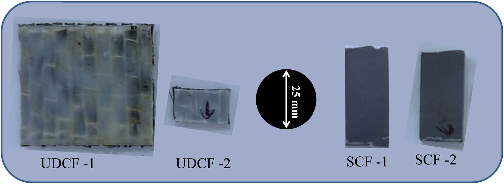
UDCF and SCF composites used for X-ray CT measurements.
3 Results and discussion
3.1 X-ray CT-scan of composites
The CT-scan images of composite samples at three selected depths, named as the top layer, middle layer and bottom layer are shown in Figure 4. Individual rovings (12K carbon fibres) are visible, and the slight misalignment of the glass fibre, i.e. misaligned white threads in the transverse direction can also be seen in Figure 4. The solid circles in the images represent the wetted zones and the dotted circles represent the dry spots (poorly wetted zones) in the composite. To observe the difference more significantly, a smaller sample of thickness 2,500 µm was also subjected to CT-scan (not shown), and it was found that the matrix wets the rovings from all four directions, but it is unable to wet the central part of the roving. From both CT-scan studies, it is found that the bottom layer is more wetted by matrix compared to the middle layer as shown in Figure 4. The same conclusion was derived using optical microscopic studies (not reported). This could be due to the usage of a thick matrix sheet (900 µm) and thick fabric reinforcement (12K roving). UDCF fabrics with 3K and 6K rovings were not available in the market to use as thin reinforcements. SCF composites of 3.2 mm thickness were analyzed using CT-scan (Figure 5). The specimen did not have any macropores in any layers. Only a few micro-cracks of 0.5–1 mm long were observed in the middle layer of the composite. This shows the packing of the SCF composite is good and devoid of pores that make it difficult for the water to penetrate. The distribution of SCF in the matrix was studied using a matrix burn-out method and is reported in our earlier study [1].
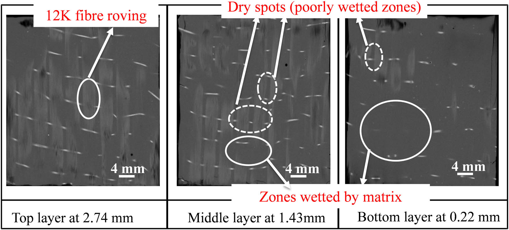
CT-scan of the UDCF-1 composite specimen having a thickness of 3.2 mm. The dotted circles indicate poorly wetted regions, which are more in the middle layer (white stitches are glass fibres used to hold the UDCF rovings).
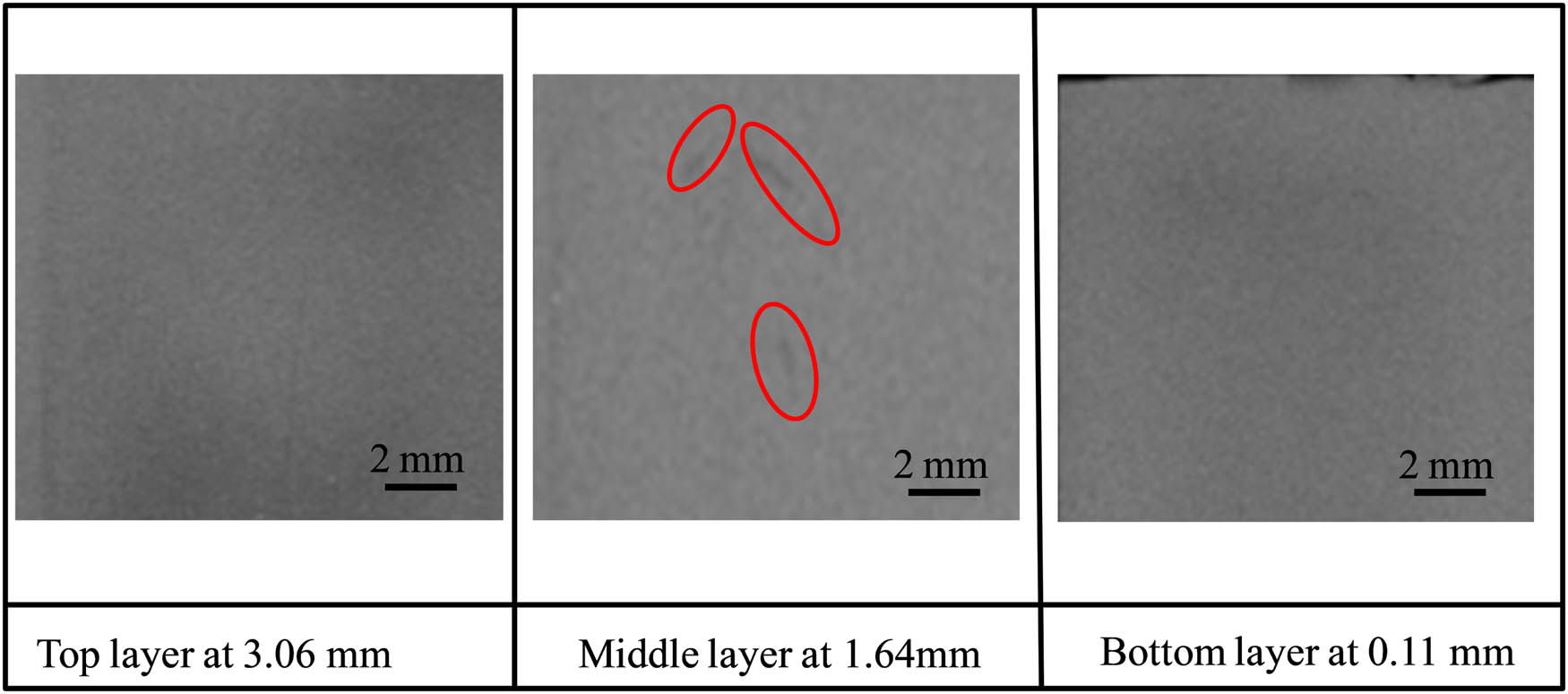
CT-scan of the SCF-1 composite specimen having a thickness of 3.2 mm. The solid circles indicate fine cracks, which are found only in the middle layer.
3.2 SEM analysis of composites
Four layers of UDCF and five layers of matrix sheets are used to make the UDCF composite and it is evident from X-ray CT scans (more number of dry spots in the middle layer) that the selected matrix sheet thickness is too high. From the SEM images, it is also visible that the fibres in the core part of the roving remain partially wetted (Figure 6b–e). These unwetted zones or dry spots in the thermoplastic composite are widely reported, which are formed due to the high melt viscosity of thermoplastic matrices [24,25]. The images in Figure 6b and d show the cross-section of fibre rovings, but slightly misaligned fibres are also seen, which eventually alters the properties of the composites. As seen from Figure 6c, interfacial voids are not seen around the fibres (between the matrix and fibre), which ensures good compatibility between the fibre and the matrix phases. It can be concluded that bonding is good but the matrix is unable to diffuse through the thick fibres zones (roving of 12,000 single fibres), which quite matches with X-ray CT data.
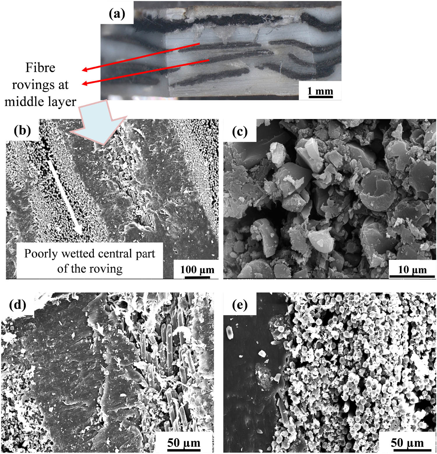
(a) The cross-section of the UDCF composite after smoothing with a microtome, (b–e) SEM images. Note the completely wetted (sides) and unwetted (central) parts of the fibre rovings.
3.3 Comparison of water absorption data
The overall water absorption of the matrix blend (PA6B), SCF composite (PA6B/SCF) and UDCF composite (PA6B/UDCF) materials is shown in Figure 7. Water absorption of the matrix blend and SCF composite was almost the same (2–2.5%), while the water absorption of the UDCF composite laminate is almost 7.5%. This difference could be due to the poorly wetted zones in UDCF composites as revealed by the X-ray CT scan and SEM images (Figures 4 and 6). Among the injection-molded specimens (PA6, PA6B, PA6/SCF), it could be seen that with the inclusion of PP and SCF fibres, the % of water absorption reduced drastically because PP and carbon fibres are hydrophobic in nature.
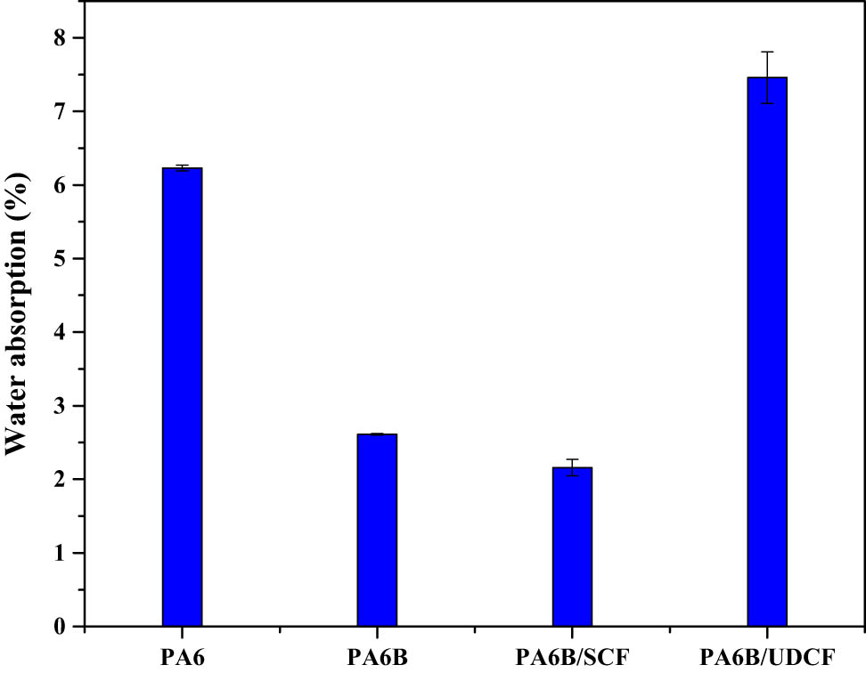
Water absorption data of the PA6, matrix blend PA6/PP/PP-g-MA (PA6B), PA6B/SCF composite, and PA6B/UDCF composite.
It can also be understood from the X-ray CT scan of SCF composites (Figure 5) that the samples have very few macro voids that also hinder water absorption. The addition of compatibilizer (PP-g-MA) was advantageous as it aids in the decrease of water absorption by reacting with the end groups of PA6, thereby reducing the free amines as seen in our earlier studies [1,4,5]. But, the sudden increase in the % of water absorption for the UDCF composite laminate could be due to the macropores present in the sample arising from the unwetted fibres or dry spots in the composite (Figures 4 and 6) and also due to the micropores (air bubbles) in the matrix material arising from compression molding. Carbon fibres are hydrophobic in nature but the sizing agent present on carbon fibres is oligomers of epoxy and has reactive end groups that might aid in accumulating water between the fibres. Due to the above two reasons, the UDCF composite laminates absorbed slightly more water than PA6. Comparing the literature values of water absorption to the values from the current study (Table 2), it can be definitely concluded that the injection-molded SCF composite showed a lower % of water absorption. However, the compression molding technique adopted for the UDCF composite processing should be modified using 3K rovings instead of 12K rovings to obtain composite laminates with good fibre-matrix wetting, which should result in a lower % of water absorption.
Water absorption data of PA6-based composites
| Composite | Fibre fraction and the processing technique | Water absorption value (%) | Reference |
|---|---|---|---|
| PA6/PP/PP-g-MA/SCF | 15 wt%, 1 mm fibres, twin-screw extrusion followed by injection molding | 2.16 ± 0.11 | This study |
| PA6/PP/PP-g-MA/UDCF | 30 wt% or 20 vol%, film stacking technique (compression molding) | 7.46 ± 0.35 | This study |
| PA6/PP/PP-g-MA/SCF | 20 wt%, 6 mm fibre, single screw extrusion followed by injection molding | 5.5 | [13] |
3.4 Comparison of the tensile strength (dry and wet)
The tensile strength of the PA6, matrix blend and composites are shown in Figure 8. Among the dry tensile strength data, the matrix blend has a lower tensile strength than others. But, as SCF fibres are added to the matrix blend, the tensile strength increased by 55% in comparison to PA6B. With the addition of UDCF fibres, ∼nine-fold increase in the tensile strength is seen due to the presence of long carbon fibres [17,18]. Compared to the SCF-reinforced composite (15 wt%), around six-fold increase in the tensile strength has been observed for the UDCF-reinforced composite (30 wt%). Hence, the addition of UDCF provides its benefit by increasing the fibre-matrix interfacial area of interaction, thereby improving the strength. In composites, the longitudinal tensile strength increases with the increase in fibre content. In SCF composites, the weight fraction of the fibre is 15 wt% and the residual fibre length is only between 50 and 100 µm (post-processing) due to which a very low increase in the tensile strength can be seen. However, in the case of SCF, the dispersion of SCF fibres in the matrix is very uniform and the adhesion between the fibre and matrix was found to be good, as the fibres are completely wetted by the matrix (Figure 5). In the case of the UDCF composite, good bonding between the fibre and matrix was seen but limited to a few zones of the composite (Figures 4 and 6). As the viscosity of the matrix blend is very high (compared to thermosets) and the weight fraction of fibres (30 wt%) also increased compared to the SCF composite, the level of “fibre wetting by matrix” decreased leading to dry spots in the core zone of the rovings, which in turn would have led to lower strength of the composite than expected. The reasons could be the usage of thick “UDCF fabric of 12K roving” and thick matrix sheets (>900 µm). Due to these thicker layers, the interlaminar shear strength (ILSS) value also became low because of which a lower tensile strength was observed [26]. The ILSS was found using a three-point bending fixture but a span length of 8 mm and a span length-thickness ratio of 4 was used (ASTM D2344). The obtained ILSS value was 22 MPa, which is lower than the value reported for the epoxy/carbon fibre composite. Ma et al. found the ILSS of PA6/carbon fibre to be 40 MPa in the wetted zone and 15 MPa in a dry or unwetted zone [27]. Hence, due to poor wetting, a lower ILSS value was obtained in the current study.
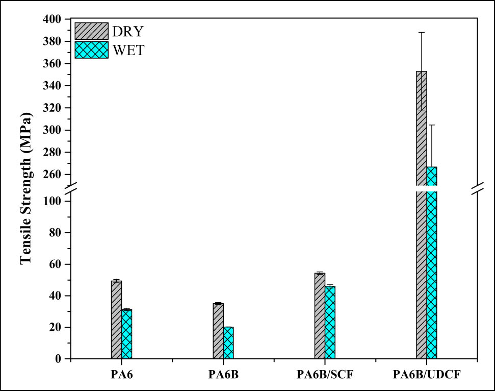
Tensile strength of the PA6, matrix blend (PA6B), SCF composite and UDCF composite in dry and wet conditions.
Among the wet samples, the matrix blend was again found to have the lowest tensile strength than others, but as SCF is added, the wet strength of the SCF composite increased by 125% compared to the wet PA6B. When compared between dry and wet tensile strengths, the % reduction is 37% for PA6, 42% for the matrix blend (PA6B) and only 15% for the SCF composite and 24.5% for the UDCF composite. The SCF composite has the combined advantage of lower water absorption (Figure 7) and a lower reduction in the tensile strength post water absorption due to the presence of PP (30 wt%) and good wetting between the fibre and matrix. The addition of a compatibilizer was advantageous even in wet conditions, as the interface between the fibre and matrix did not get affected due to which better properties were observed in SCF composites. In wet UDCF composites, the voids formed due to the unwetted zones are filled with water, which in turn contributed a 24.5% decrease in the tensile strength compared to dry UDCF composites. The accumulation of water could have led to weaker interface and the existing misalignment of fibres cumulatively would have affected the load transfer mechanism.
From the literature values shown in Table 3, it is clear that a higher length of SCF has to be used in the case of SCF-reinforced composite and for the UDCF composite, either prepregs/semiprepregs should be used to obtain higher strength composites. However, considering the % reduction in strength after saturating with water, it can be seen that in the current study, the reduction is only 15%, whereas in the literature it is greater than 35%. Hence, from the current study, the novel matrix blend can be effectively used with SCF fibres to obtain an optimum wet tensile strength of the composites.
Tensile strength of PA6-based composites
| Composite | Fibre fraction and the processing technique | Tensile strength (MPa) | Reference |
|---|---|---|---|
| PA6B/SCF (PA6/PP/PP-g-MA/SCF) | 15 wt%, 1 mm fibres, twin-screw extrusion followed by injection molding | Dry: 54 ± 0.77 | This study |
| Wet: 46 ± 1.2 | |||
| (15% reduction) | |||
| PA6B/UDCF (PA6/PP/PP-g-MA/UDCF) | 30 wt% or 20 vol%, film stacking technique (compression molding) | Dry: 353 ± 35 | This study |
| Wet: 266 ± 38 | |||
| (24.5% reduction) | |||
| PA6/PP/PP-g-MA/SCF | 20 wt%, 6 mm fibre, single-screw extrusion followed by injection molding | Dry: 142 | [13] |
| Wet: 88 | |||
| (38% reduction) |
For SCF composites having a low number of interfacial voids and good wetting, the percentage of elongation was 9.8% in both dry and wet states. This indifference in elongation showed that the water absorption did not plasticize the matrix due to which a lower reduction in the tensile strength was found. For the UDCF composite, it was observed that elastic deformation exceeds even above 1.5% strain, which corresponds to the elongation at the break of the carbon fibre. The overall elongation of the composite was found to be 13.8% indicating that the composite was able to behave as a plastic up to the point of break, which shows the existence of good interfacial adhesion despite having a few unwetted zones. The tensile modulus of the SCF composite was found to decrease from 4.9 GPa (dry) to 4.1 GPa (wet). This minimal loss again proved that the matrix blend-based SCF composites can be used for humid applications. The effect of carbon fibre reinforcement is more evident as the SCF composite modulus is “3 times” and UDCF composite modulus is “17 times” higher than that of the “matrix blend”. The tensile modulus of UDCF was found to be 27.4 GPa. Even though this value is 5 times higher than that of the SCF composite, it is quite low compared to the PA6/UDCF composite value, which could be due to the unwetted zones as reported earlier. To increase the wetting and interfacial adhesion in the central part of the roving’s in UDCF mat, the matrix sheet thickness has to be reduced, as it will aid in better wettability of fibre rovings in the final composite because the thin matrix sheets can melt and flow easily (low viscosity) through the UDCF fibre mat. Modulus and elongation were not measured for wet UDCF samples due to the difficulty of fixing the strain gauges on the wet surfaces.
An attempt has been made to reduce the thickness of matrix sheets. NBBSA (n-benzyl butyl sulfonamide) plasticizer was mixed with matrix pellets to obtain thin matrix sheets, and the comparison of sheet properties was carried out using the tensile test. The PA6B sheet had better strength and stiffness than the plasticized PA6B sheet. Though plasticizer could reduce the thickness of the sheet by 200 µm, but owing to its lower tensile strength, this “plasticized matrix” was not further considered in making the composite.
3.5 Comparison of the impact strength (dry and wet)
For laminate composites, the Izod impact test cannot be used, as the composite fracture mechanism is much complex than the monolithic plastic or short fibre-reinforced composites. So, two types of impact tests were used in this study. The injection-molded specimens were tested using an Izod test and compression-molded specimens were tested using a low-velocity impact (LVI) test. In the Izod test, the notch acts as a stress concentrator and when the pendulum strikes the samples, it only provides the energy required for crack propagation in the sample [18]. Since crack initiation, crack propagation and termination follows a different mechanism in the UDCF laminate composites (notch absent and having long fibres), it is important to measure the total energy required to break the sample and hence the LVI test is used. For comparison, all impact test results are converted to “Joules,” as shown in Figure 9.
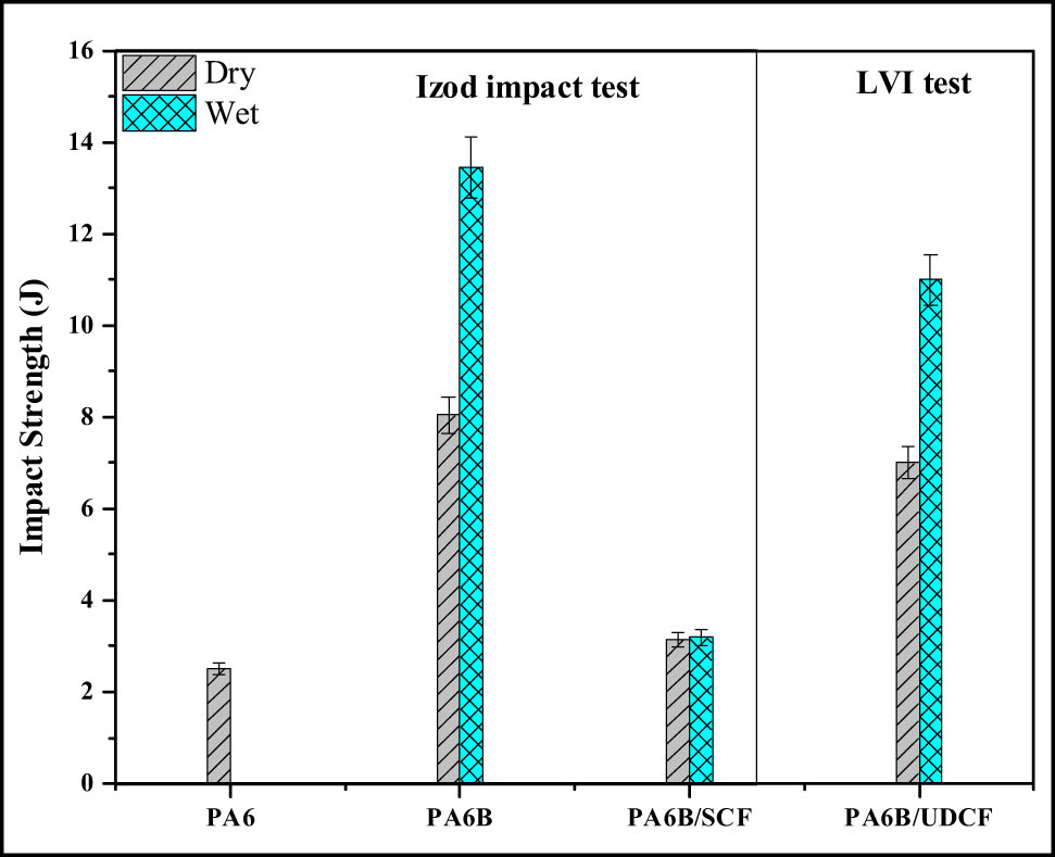
Impact strength of the injection-molded PA6, matrix blend (PA6B), SCF composite and UDCF composite in dry and wet conditions. LVI: low-velocity impact test.
The Izod-dry impact strength of the matrix blend (PA6B) was higher than the PA6 and SCF composite. The addition of a compatibilizer (3 phr PP-g-MA) and PP (30 wt%) with a domain size of 820 µm could have led to higher impact strength in the blend [4]. Whereas in SCF composites, the brittle carbon fibres act as stress concentrator (random fibres neither absorb energy nor arrests a propagating crack), which could have led to a decrease in the impact strength [1]. One more reason could be the low residual length of SCF fibres, i.e. 50–100 µm. The wet PA6B blend showed a 67% increase in the impact strength (compared to dry) due to the plasticization of PA6. The synergistic effect of PP and SCF led to “no increase” in the impact strength of the SCF composite when compared between dry and wet states.
From the LVI test, the UDCF samples showed a higher impact strength in comparison to SCF composites, which could be due to the few unwetted zones in UDCF composites (Figure 4). During the LVI test, the dry samples broke into two halves in the longitudinal direction owing to poor wetting in the central part of rovings. Whereas in wet conditions, the samples had imprints and did not break completely showing the plasticization of the matrix due to water absorption, which in turn caused a 50% increase in the impact strength (Table 4). In UDCF composites, which are processed using compression molding, the free end groups of PA6 would have reacted with water and plasticized the matrix. Hence, the impact strength of wet UDCF composites would have increased making them suitable for components of optimum strength and toughness in humid conditions.
Impact strength of PA6-based composites
| Composite | Impact testing technique | Impact strength | Reference |
|---|---|---|---|
| PA6B/SCF (PA6/PP/PP-g-MA/SCF) | Notched-Izod (15 wt% SCF fibres) | Dry: 9.4 ± 0.1 kJ/m2 | This study |
| Wet: 9.5 ± 0.1 kJ/m2 | |||
| PA6B/UDCF (PA6/PP/PP-g-MA/UDCF) | Low-velocity impact (30 wt% UDCF fibres) | Dry: 7.06 J | This study |
| Wet: 11.4 J | |||
| PA6/PPS/SCF | Notched-Izod (15 wt% SCF fibres) | ∼11 kJ/m2 (dry) | [28] |
Note: PPS = polyphenylene sulfide.
3.6 Comparison between tensile and impact properties for wet composites
When compared between dry and wet SCF composites, wet composites had a 15% reduction in the tensile strength (Table 3) and “no increase” in the impact strength (Table 4) than dry composites, which could be due to fewer number of interfacial voids (Figure 5). When compared between dry and wet UDCF composites, wet composites had a 24.5% reduction in the tensile strength (Table 3) and a 61% increase in the impact strength (Table 4) than the dry composites. Synergistic effects of plasticization of the matrix and the presence of interfacial voids in the UDCF composite (Figures 4 and 6) cause improvement in the impact strength and reduction of the tensile strength due to water absorption (Table 4). For making the high impact and high tensile strength components, which are meant for humid or underwater conditions, UDCF composites can be recommended keeping the factor of safety into consideration. The above composite properties will vary with reinforcement and temperature. At higher temperatures, water absorption will be high and interfacial bonding between the fibre and matrix becomes weaker. So, the current experimental results are limited to only room temperature, carbon fibre reinforcement, and 2-D specimens. But, this novel matrix blend can be used to make 3-D composites with glass or other fibre reinforcements. For applications requiring high temperatures, extensive studies need to be conducted because of the lower glass transition temperature of the matrix blend compared to thermosets.
4 Conclusion
This study focuses on the influence of carbon fibre reinforcement on the properties of the novel matrix blend “PA6/PP/PP-g-MA”, which is found to be a water-resistant matrix (only a 2% weight increase was observed).
The addition of SCF fibres resulted in a 55% increase in the tensile strength, 3 times increase in tensile modulus, which could be due to the carbon fibres and good wetting throughout the thickness as confirmed by X-ray CT. This good wetting caused only 15% reduction in the tensile strength and no change in the impact strength when dry and wet composites are compared. Hence, SCF composites are recommended for both humid and non-humid conditions wherein small loads are anticipated.
X-ray CT of UDCF composites revealed good wetting only in the top and bottom layers but poor wetting in middle layers, which was also confirmed by SEM fractography (poor wetting in the core part of the roving) and lower value of ILSS (22 MPa). Due to this, the wet UDCF composite resulted in a 61% increase in the impact strength (from 7 to 11 J) and a 24.5% decrease in the tensile strength (compared to dry), which could be advantageous in making composites with high toughness for humid applications wherein medium loads are anticipated.
For better tensile properties, the UDCF fabric of 3K rovings instead of 12K rovings and thin sheets of the matrix (300–400 µm) instead of 900 µm should be studied. An attempt was made for making a thinner matrix sheet of 700 µm using NBBSA plasticizer, but at the expense of a matrix tensile strength.
From this study, it is understood that the novel matrix blend can also be used for making long fibre (UDCF) composites, which increase the opportunity of using thermoplastic matrices such as PA6 in place of a thermosetting matrix in preparing underwater components of submarine/ships.
Acknowledgement
The authors would like to thank Dr Sujith, Mr Somireddy, Mr Tarun Sai, Mr Shivaram, Mr Sankeerth Reddy, CAL Division, Chemical Department, Civil/Mechanical Department for their co-operation and suggestions while conducting these experiments. First author would like to thank BITS Pilani University for providing Institute Scholarship during this work.
-
Conflict of interest: No potential conflict of interest was reported by the authors.
Appendix
Processing of matrix sheets (PA6/PP) and UDCF composites (long carbon fibre-reinforced PA6/PP composite)
During matrix processing, 1 mm spacer plate is used for making the matrix sheet of 700–900 µm thickness. Initially, the top mold temperature was set to 240°C and the bottom mold temperature was gradually brought to 260°C. Once the bottom mold is heated to 230°C, the mold is opened and high viscous silicone oil is applied as a release agent and 35 g of matrix pellets was spread uniformly and the mold was closed. After the bottom mold attains 240°C, a pressure of 50 bar is applied for a period of 30 min while the temperature of the bottom mold increases and stabilizes at 260°C. The heaters are turned off and water is circulated for cooling the mold while the specimen is under 50 bar pressure. The overall time taken for preparing the matrix sheet is 2.5 h. The flow rate of cooling water is 4 L/min and the cooling rate is 7°C/min. A few matrix sheets had double layers because of uneven heating of the matrix pellets, which may be due to poor thermal conductivity of the material as well as the non-uniformity in heating and these were not used for composite processing.
During composite processing, a thin layer of highly viscous silicone oil is applied on a 4 mm spacer plate and the alternating layers of the matrix and fibre mats were placed and closed the mold (4 layers of UDCF mats, 5 layers of matrix sheets), as shown in Figure 1. The first cycle (Figure 1d) ensures that the fibre and matrix layers are compacted without any misalignment resulting in a 3–4 mm thick laminate, whereas the second cycle (Figure 1e) aids in better wetting of fibre rovings and the removal of the excess matrix due to more compaction (spacer plate of 2 mm is used instead of 4 mm) resulting in a 2.5–3 mm thin laminate composite. In the case of cycle-2, heaters are turned-off and the composite sample is allowed to cool by airflow up to 175°C followed by water cooling up to 100°C. The release agent silicone oil had a tendency to oxidize at 250°C and led to the formation of brown spots on the plastic sheet. Care was taken not to exceed the sample surface temperature above 250°C.
References
[1] Aparna S, Purnima D, Adusumalli RB. Effect of short carbon fiber content and water absorption on tensile and impact properties of PA6/PP blend based composites. Polym Compos. 2020;41(12):5167–81.10.1002/pc.25784Search in Google Scholar
[2] Viswanathan A. Wallace carothers: more than the inventor of nylon and neoprene. World Pat Inf. 2010;32(4):300–5.10.1016/j.wpi.2009.09.004Search in Google Scholar
[3] Aparna S, Purnima D, Adusumalli RB. Review on various compatibilizers and its effect on mechanical properties of compatibilized nylon blends. Polym Plast Technol Eng. 2017;56(6):617–34.10.1080/03602559.2016.1233280Search in Google Scholar
[4] Aparna S, Doddipatla P. Influence of PP content on mechanical properties, water absorption, and morphology in PA6/PP blend. J Appl Polym Sci. 2019;136(25):1–13.10.1002/app.47690Search in Google Scholar
[5] Aparna S, Purnima D, Adusumalli RB. Effect of compatibilizer on the properties of polyamide 6 blend based carbon fiber reinforced composites. Fibers Polym. 2018;19(6):1335–46.10.1007/s12221-018-1009-4Search in Google Scholar
[6] Bahadur S, Gong D, Anderegg W. Studies of worn surfaces and the transfer film formed in sliding by CuS-filled and carbon fiber-reinforced nylon against a steel surface. Wear. 1995;181–183:227–35.10.1016/0043-1648(94)07058-XSearch in Google Scholar
[7] Karsli NG, Aytac A. Tensile and thermomechanical properties of short carbon fiber reinforced polyamide 6 composites. Compos Part B Eng. 2013;51:270–5.10.1016/j.compositesb.2013.03.023Search in Google Scholar
[8] Feng N, Wang X, Wu D. Surface modification of recycled carbon fiber and its reinforcement effect on nylon 6 composites: mechanical properties, morphology and crystallization behaviors. Curr Appl Phys. 2013;13(9):2038–50.10.1016/j.cap.2013.09.009Search in Google Scholar
[9] Luo H, Xiong G, Ma C, Li D, Wan Y. Preparation and performance of long carbon fiber reinforced polyamide 6 composites injection-molded from core/shell structured pellets. Mater Des. 2014;64:294–300.10.1016/j.matdes.2014.07.054Search in Google Scholar
[10] Li Y, Xu J, Wei Z, Xu Y, Song P, Chen G, et al. Mechanical properties and nonisothermal crystallization of polyamide 6/carbon fiber composites toughened by maleated elastomers. Polym Compos. 2014;35:2170–9.10.1002/pc.22881Search in Google Scholar
[11] Malekzadeh Y, Shelesh-Nezhad K. The effects of HNO3-surface treated carbon fiber and nano-CaCO3 inclusions on dynamic mechanical and heat properties of PA6/ABS-based composites. J Thermoplast Compos Mater. 2019;32(7):867–83.10.1177/0892705718804604Search in Google Scholar
[12] Arsad A, Rahmat AR, Hassan A, Iskandar SN. Mechanical and rheological properties of PA6/ABS blends – with and without short glass fiber. J Reinf Plast Compos. 2010;29(18):2808–20.10.1177/0731684409360076Search in Google Scholar
[13] Do VT, Nguyen-Tran HD, Chun DM. Effect of polypropylene on the mechanical properties and water absorption of carbon-fiber-reinforced-polyamide-6/polypropylene composite. Compos Struct. 2016;150:240–5.10.1016/j.compstruct.2016.05.011Search in Google Scholar
[14] Li B, Zhang Y, Bai X, Wang S, Ji J. Effect of PPO-g-MA on structures and properties of PPO/PA6/short glass fiber composites. J Polym Sci Part B Polym Phys. 2009;47:2188–97.10.1002/polb.21815Search in Google Scholar
[15] Botelho EC, Rezende MC, Lauke B. Mechanical behavior of carbon fiber reinforced polyamide composites. Compos Sci Technol. 2003;63(13):1843–55.10.1016/S0266-3538(03)00119-2Search in Google Scholar
[16] Ma Y, Yokozeki T, Ueda M, Sugahara T, Yang Y, Hamad H. Effect of polyurethane dispersion as surface treatment for carbon fabrics on mechanical properties of carbon/Nylon composites. Compos Sci Technol. 2017;151:268–81.10.1016/j.compscitech.2017.08.031Search in Google Scholar
[17] Chawla KK. Composite materials: science and engineering. 3rd edn. New York: Springer; 1998.10.1007/978-1-4757-2966-5Search in Google Scholar
[18] Agarwal BD, Broutman LJ, Chandrashekhara K. Analysis and performance of fiber composites. 3rd edn. Hoboken, NJ: John Wiley & Sons, Inc; 2006.Search in Google Scholar
[19] Canale G, Kinawy M, Sathujoda P, Maligno A, Citarella RG. Moisture absorption in thick composite plates: modelling and experiments. Multidiscip Model Mater Struct. 2020;16(3):439–47.10.1108/MMMS-06-2019-0119Search in Google Scholar
[20] Rubino F, Nisticò A, Tucci F, Carlone P. Marine application of fiber reinforced composites: a review. J Mar Sci Eng. 2020;8(1):26.10.3390/jmse8010026Search in Google Scholar
[21] Rubino F, Carlone P. A semi-analytical model to predict infusion time and reinforcement thickness in VARTM and SCRIMP processes. Polymers. 2019;11(1):20.10.3390/polym11010020Search in Google Scholar PubMed PubMed Central
[22] Michaud V. A review of non-saturated resin flow in liquid composite moulding processes. Transp Porous Media. 2016;115(3):581–601.10.1007/s11242-016-0629-7Search in Google Scholar
[23] Arhant M, Le Gac PY, Le Gall M, Burtin C, Briançon C, Davies P. Effect of sea water and humidity on the tensile and compressive properties of carbon-polyamide 6 laminates. Compos Part A Appl Sci Manuf. 2016;91:250–61.10.1016/j.compositesa.2016.10.012Search in Google Scholar
[24] Botelho EC, Rezende MC. Evaluation by free vibration method of moisture absorption effects in polyamide/carbon fiber laminates. J Thermoplast Compos Mater. 2010;23(2):207–25.10.1177/0892705709342614Search in Google Scholar
[25] Ma Y, Ueda M, Yokozeki T, Sugahara T, Yang Y, Hamada H. Comparative study of the mechanical properties and failure behavior of carbon fiber/epoxy and carbon fiber/polyamide 6 unidirectional composites. Compos Struct. 2017;160:89–99.10.1016/j.compstruct.2016.10.037Search in Google Scholar
[26] Adusumalli R, Reifferscheid M, Weber HK, Roeder T, Sixta H, Gindl W. Shear strength of the lyocell fiber/polymer matrix interface evaluated with the microbond technique. J Compos Mater. 2012;46(3):359–67.10.1177/0021998310382312Search in Google Scholar
[27] Ma Y, Yang Y, Sugahara T, Hamada H. A study on the failure behavior and mechanical properties of unidirectional fiber reinforced thermosetting and thermoplastic composites. Compos Part B. 2016;99:162–72.10.1016/j.compositesb.2016.06.005Search in Google Scholar
[28] Zhou S, Zhang Q, Wu C, Huang J. Effect of carbon fiber reinforcement on the mechanical and tribological properties of polyamide 6/polyphenylene sulfide composites. Mater Des. 2013;44:493–9.10.1016/j.matdes.2012.08.029Search in Google Scholar
© 2021 Aparna Sridhar et al., published by De Gruyter
This work is licensed under the Creative Commons Attribution 4.0 International License.
Articles in the same Issue
- Effects of Material Constructions on Supersonic Flutter Characteristics for Composite Rectangular Plates Reinforced with Carbon Nano-structures
- Processing of Hollow Glass Microspheres (HGM) filled Epoxy Syntactic Foam Composites with improved Structural Characteristics
- Investigation on the anti-penetration performance of the steel/nylon sandwich plate
- Flexural bearing capacity and failure mechanism of CFRP-aluminum laminate beam with double-channel cross-section
- In-Plane Permeability Measurement of Biaxial Woven Fabrics by 2D-Radial Flow Method
- Regular Articles
- Real time defect detection during composite layup via Tactile Shape Sensing
- Mechanical and durability properties of GFRP bars exposed to aggressive solution environments
- Cushioning energy absorption of paper corrugation tubes with regular polygonal cross-section under axial static compression
- An investigation on the degradation behaviors of Mg wires/PLA composite for bone fixation implants: influence of wire content and load mode
- Compressive bearing capacity and failure mechanism of CFRP–aluminum laminate column with single-channel cross section
- Self-Fibers Compacting Concrete Properties Reinforced with Propylene Fibers
- Study on the fabrication of in-situ TiB2/Al composite by electroslag melting
- Characterization and Comparison Research on Composite of Alluvial Clayey Soil Modified with Fine Aggregates of Construction Waste and Fly Ash
- Axial and lateral stiffness of spherical self-balancing fiber reinforced rubber pipes under internal pressure
- Influence of technical parameters on the structure of annular axis braided preforms
- Nano titanium oxide for modifying water physical property and acid-resistance of alluvial soil in Yangtze River estuary
- Modified Halpin–Tsai equation for predicting interfacial effect in water diffusion process
- Experimental research on effect of opening configuration and reinforcement method on buckling and strength analyses of spar web made of composite material
- Photoluminescence characteristics and energy transfer phenomena in Ce3+-doped YVO4 single crystal
- Influence of fiber type on mechanical properties of lightweight cement-based composites
- Mechanical and fracture properties of steel fiber-reinforced geopolymer concrete
- Handcrafted digital light processing apparatus for additively manufacturing oral-prosthesis targeted nano-ceramic resin composites
- 3D printing path planning algorithm for thin walled and complex devices
- Material-removing machining wastes as a filler of a polymer concrete (industrial chips as a filler of a polymer concrete)
- The electrochemical performance and modification mechanism of the corrosion inhibitor on concrete
- Evaluation of the applicability of different viscoelasticity constitutive models in bamboo scrimber short-term tensile creep property research
- Experimental and microstructure analysis of the penetration resistance of composite structures
- Ultrasensitive analysis of SW-BNNT with an extra attached mass
- Active vibration suppression of wind turbine blades integrated with piezoelectric sensors
- Delamination properties and in situ damage monitoring of z-pinned carbon fiber/epoxy composites
- Analysis of the influence of asymmetric geological conditions on stability of high arch dam
- Measurement and simulation validation of numerical model parameters of fresh concrete
- Tuning the through-thickness orientation of 1D nanocarbons to enhance the electrical conductivity and ILSS of hierarchical CFRP composites
- Performance improvements of a short glass fiber-reinforced PA66 composite
- Investigation on the acoustic properties of structural gradient 316L stainless steel hollow spheres composites
- Experimental studies on the dynamic viscoelastic properties of basalt fiber-reinforced asphalt mixtures
- Hot deformation behavior of nano-Al2O3-dispersion-strengthened Cu20W composite
- Synthesize and characterization of conductive nano silver/graphene oxide composites
- Analysis and optimization of mechanical properties of recycled concrete based on aggregate characteristics
- Synthesis and characterization of polyurethane–polysiloxane block copolymers modified by α,ω-hydroxyalkyl polysiloxanes with methacrylate side chain
- Buckling analysis of thin-walled metal liner of cylindrical composite overwrapped pressure vessels with depressions after autofrettage processing
- Use of polypropylene fibres to increase the resistance of reinforcement to chloride corrosion in concretes
- Oblique penetration mechanism of hybrid composite laminates
- Comparative study between dry and wet properties of thermoplastic PA6/PP novel matrix-based carbon fibre composites
- Experimental study on the low-velocity impact failure mechanism of foam core sandwich panels with shape memory alloy hybrid face-sheets
- Preparation, optical properties, and thermal stability of polyvinyl butyral composite films containing core (lanthanum hexaboride)–shell (titanium dioxide)-structured nanoparticles
- Research on the size effect of roughness on rock uniaxial compressive strength and characteristic strength
- Research on the mechanical model of cord-reinforced air spring with winding formation
- Experimental study on the influence of mixing time on concrete performance under different mixing modes
- A continuum damage model for fatigue life prediction of 2.5D woven composites
- Investigation of the influence of recyclate content on Poisson number of composites
- A hard-core soft-shell model for vibration condition of fresh concrete based on low water-cement ratio concrete
- Retraction
- Thermal and mechanical characteristics of cement nanocomposites
- Influence of class F fly ash and silica nano-micro powder on water permeability and thermal properties of high performance cementitious composites
- Effects of fly ash and cement content on rheological, mechanical, and transport properties of high-performance self-compacting concrete
- Erratum
- Inverse analysis of concrete meso-constitutive model parameters considering aggregate size effect
- Special Issue: MDA 2020
- Comparison of the shear behavior in graphite-epoxy composites evaluated by means of biaxial test and off-axis tension test
- Photosynthetic textile biocomposites: Using laboratory testing and digital fabrication to develop flexible living building materials
- Study of gypsum composites with fine solid aggregates at elevated temperatures
- Optimization for drilling process of metal-composite aeronautical structures
- Engineering of composite materials made of epoxy resins modified with recycled fine aggregate
- Evaluation of carbon fiber reinforced polymer – CFRP – machining by applying industrial robots
- Experimental and analytical study of bio-based epoxy composite materials for strengthening reinforced concrete structures
- Environmental effects on mode II fracture toughness of unidirectional E-glass/vinyl ester laminated composites
- Special Issue: NCM4EA
- Effect and mechanism of different excitation modes on the activities of the recycled brick micropowder