Environmental effects on mode II fracture toughness of unidirectional E-glass/vinyl ester laminated composites
-
Mazaher Salamt-Talab
 ,
Fatemeh Delzendehrooy
,
Fatemeh Delzendehrooy

Abstract
In this article, mode II fracture toughness (
Nomenclature
-
-
crack length
-
-
initial crack length
-
-
width of the ENF specimen
-
-
compliance
-
-
double cantilever beam
-
-
longitudinal modulus
-
-
transvers modulus
- E fx
-
flexural modulus
- ENF
-
end-notched-flexure
-
-
mode I strain energy release rate
-
-
mode II strain energy release rate
-
-
mode I critical strain energy release rate
-
-
mode II critical strain energy release rate
-
-
initial stiffness of cohesive zone model
-
-
in-plane shear modulus
-
-
maximum cohesive shear traction
- MMB
-
mixed mode bending
-
-
applied load
-
-
separation
-
-
separation at initiation of damage
-
-
separation at final point of damage
-
-
slope of the regression line
-
-
span length
-
-
half of the total length of the specimen
-
-
load line displacement
-
-
in-plane Poisson’s ratio
1 Introduction
Nowadays, polymeric matrix composites are widely used in a variety of industrial sectors especially in aerospace and automotive industries due to their advantages such as corrosion reduction. Hence, it is vital to characterize the properties and determine the damage mechanisms of these materials. Delamination is one of the important destructive phenomena and a critical failure mode, which occurred in composite structures as a result of high peel loads and the low transverse strength of the composites [1,2,3,4,5,6]. The presence of delamination will lead to the premature buckling of the laminate, intrusion of moisture, stiffness degradation, loss of fatigue life, and even the collapse of the structure [6,7,8,9]. Therefore, the study of delamination phenomena in laminated composites and their fracture toughness to predict the failure has significant importance [10]. Temperature variation, humidity, and impact are important factors involved in the occurrence of delamination [11]. In the selection of fiber and resin, the application of the composite and also environmental factors facing them have a significant role. The resistance of composite materials against delamination is significantly affected by environmental conditions such as temperature and humidity, which may occur during service or maintenance programs [12]. Mechanical aging level in composite materials is a function of aging time, and its rate depends on the environmental condition and the applied load. The variety of influencing parameters makes accurate prediction of the aging process of composites difficult [13]. Therefore, most studies analyze the effects of environmental conditions on the mechanical properties of composite laminates, experimentally. Zenasni et al. [14,15] investigated experimental characterization of the mechanical properties of three types of woven fabric composites taking into account the effects of hygrothermal and hygro–thermo–mechanical aging. The specimens were exposed to moisture–thermal and moisture–thermal–mechanical aging conditions at 70℃ for 0, 30, 60, 120, and 180 days. The mechanical characterization was carried out using mode I, double cantilever beam (DCB), and mode II, ENF interlaminar fracture tests. Woven (2/2 Twill, 8-Harness Satin) glass fiber and 8-Harness Satin carbon fiber were used. The matrix was polyetherimide (PEI). The results of mode I for the hygrothermal condition showed that delamination energy experiences a lower loss over the aging time for the 8-Harness Satin fabric instead of the 2/2 Twill fabric. Moreover, it was found that the delamination energy decreases with exposure time for specimens reinforced with glass fibers rather than specimens reinforced with carbon fibers. Similar to mode I, the result of mode II showed that 2/2 Twill specimens were less resistant to fracture than the 8-Harness Satin. Also, the samples reinforced by carbon fiber were found to be more brittle than samples reinforced by glass fiber. Experimental mode I fracture characterization of samples that were exposed to hygro–thermo–mechanical aging conditions showed that the samples reinforced by carbon fiber and glass fiber have a slight decrease in resistance. Conversely, the glass fiber-reinforced 8-Harness Satin material continued to behave strangely as in hygrothermal aging. Its strength was improved in the first 30 days, and this property was subsequently maintained until 180 days. In mode II fracture, the behavior of three materials was very similar to that of mode I, although the behavior of the glass fiber reinforced 8-Harness Satin material is even more anomalous. Zhao et al. [16] investigated the effects of seawater immersion on the delamination behavior of a woven E-glass/bismaleimide (BMI) composite at different temperatures (25, 50, and 80°C) for 6,000 h under mode I, mode II, and mixed-mode I/II loadings. The results showed that for mode I DCB tests, long-term seawater exposure caused a significant decrease (25%) in fracture toughness for the samples immersed at 80°C. However, for the specimens immersed at 50°C, the initiation of the delamination was unaffected, while the propagation resistance increased with the delamination growth. In the case of the mode II ENF tests, the results showed an unstable delamination growth. Although the fracture toughness decreased for samples immersed at 50°C, this parameter increased significantly for specimens immersed at 80°C. In the case of mixed-mode tests, the seawater exposure and increase in the immersion temperature would generally decrease the mixed-mode fracture toughness. It is worth noting that due to the plasticization of the matrix and higher ductility of the specimen after immersion, most of the wet specimens generally showed increased resistance against delamination. Scida et al. [17] studied the effects of accelerated aging conditions on specimens manufactured by woven fabrics kept for 1,300 h at 70°C with 95% relative humidity. The materials studied in their research were two composites composed of glass fiber reinforcement (twill and satin weave) with two types of epoxy resin matrixes (120°C class called R1 and a 180°C class called R2). Interlaminar delamination tests were carried out on the DCB specimens for mode I, ENF specimens for mode II, and mixed-mode bending (MMB) specimens for the mixed-mode loading condition. Also, to investigate the parameters of composite degradation under loading and aging conditions and understand damage mechanisms, techniques such as acoustic emissions and microscopic observations were conducted. The results showed that the R1 epoxy matrix was very absorbent, and the fibers did not protect the laminated composites, which affects the final mechanical properties of laminates. However, the R2 matrix offers efficient fibers protection against aging, and consequently, the mechanical properties remain almost unchanged.
Srivastava and Hogg [18] investigated the effect of moisture on the fracture toughness of mode I and mode II of aluminum tri-hydrate and polyethylene filled and unfilled quasi-isotropic glass fiber–reinforced epoxy-vinyl ester resin (GFRP) composites. Specimens were immersed in water at room temperature (20°C) for 8 months and at an interval of every 2 months, and the fracture energy in mode I (G Ic) and the mode II fracture energy (G IIc) values were obtained. Also, some samples were exposed to hot water at 40°C. The results indicated that the moisture content and diffusion coefficients increase with the increase of the weight of the filler content. Also in the case of mode I, the toughness of all composites increased with an increase in moisture uptake. However, the mode II toughness was relatively unaffected. Selzer and Friedrich [19] investigated the effect of moisture absorption on the mode II fracture toughness of unidirectional carbon fiber composites. In their study, three different matrices including two thermosetting matrices (unmodified and toughness-modified epoxy [EP and EPmoa]) and one thermoplastic matrix (semicrystalline polyetheretherketone [PEEK]) were used. The manufactured samples were exposed to water at different temperatures (23, 70, and 100°C) for various time periods. The results showed that although G Ic increases with the moisture content of the samples, G IIc decreases with aging time.
All previous studies were limited to the experimental investigation of the effect of environmental conditions such as moisture and temperature on fracture toughness. In the current study, the effect of sulfuric acid aging at two different temperatures (25 and 90°C) on mode II fracture toughness of unidirectional E-glass/vinyl ester composites was investigated. Finite element simulation using the CZM was also performed to predict the global response of the delaminated specimens.
2 Experimental procedure
2.1 Materials and properties
In the present study, the unidirectional E-glass fibers with 200 g/m2 aerial density and Hetron 922 epoxy vinyl ester resin was used as the fibers and matrix of the composite, respectively. The mechanical properties of Hetron 922 resin are presented in Table 1.
Mechanical properties of Hetron 922 vinyl ester resin [20]
| Properties | Value |
|---|---|
| Tensile modulus
|
3.17 (GPa) |
| Tensile strength | 86 (MPa) |
| Flexural strength | 141 (MPa) |
| Density of liquid
|
1.04 (g/cm3) |
| Density of solid
|
1.14 (g/cm3) |
2.2 Specimens manufacturing
E-glass fibers with a width 170 mm and a total length of 200 mm were used. The samples were manufactured using the hand lay-up method with the

Schematic of a tested sample.
Geometrical parameters of ENF specimens
| l L (mm) | a 0 (mm) | l s (mm) | b (mm) |
|---|---|---|---|
| 70 | 30 | 100 | 25 |
2.3 Testing procedures
2.3.1 Environmental condition
To apply the environmental conditions, two glass containers were prepared, and the samples were divided into two groups; the first group was placed in a container at 25°C and the second group was placed in another container at 90°C. Then, a two-component solution of distilled water and sulfuric acid with a concentration of 30 wt% and purity of 98 wt% were prepared and poured into the containers. To expose all the samples to the solution, a glass-shaped separator was placed between them as shown in Figure 2. According to ASTM D543 [21], the solution was stirred regularly during exposure time. Then, one of the containers was placed at 25°C for different periods (0, 1, 2, 4, and 8 weeks), and the other was heated in an electric oven at 90°C for 0, 3, 6, 9, and 12 days.

Arrangement of specimens separated by glass separators in the solution.
2.3.2 Test method
In this study, the flexure test according to ASTM D7905 [22] was carried out on ENF specimens to measure the fracture toughness of mode II and the flexural modulus of E/vinyl ester composites. In the current study, at least four specimens are tested for each condition. Specimens were tested utilizing a universal testing machine (STM-250) with a high precision load cell with the capacity of 2,000 kgf. The tests were carried out under displacement control conditions with a crosshead rate of 0.5 mm/min. Figure 3 illustrates the specimen in the flexural test. According to ASTM D7905, compliance tests were conducted on the specimens with different pre-crack sizes. For this goal, the initial crack lengths were determined as 20, 25, 35, and 40 mm, while the load corresponding to each crack length was limited only to half of the maximum bearable load corresponding to crack initiation. Following each loading step, the specimens should be unloaded under displacement control conditions. It should be noted that both the loading and unloading in the compliance tests were performed at 0.5 mm/min crosshead speed. Afterward, the fracture tests were carried out on the ENF samples where the pre-crack size was set to 30 mm. By using the compliance data, the fracture energy was obtained using the following equation:
where P is the applied load, a is the corresponding crack length, and b is the width of the samples. Based on ASTM D7905, the coefficient m is determined by the least square analysis on the experimental compliance
where the coefficient m is the slope of the regression line and A is the intercept [23].

ENF specimen under fracture test.
3 Numerical procedure
Among the common numerical methods, many researchers used the cohesive zone models as an efficient and fast convergence method to simulate the delamination initiation and propagation of composite laminates. The reported numerical results show that the cohesive zone model can be used to simulate crack initiation and propagation in different fracture modes, e.g., mode I and II and mixed mode I/II, accurately [24,25,26,27]. The constitutive equation of interface elements is based on the traction-separation law. This law has different shapes such as bilinear, trilinear, trapezoidal, and exponential forms [28]. In finite element modeling, one layer of the element with small or zero thickness is considered in the probable path of the delamination propagation. In the current study, the delamination propagation was simulated using the bilinear cohesive zone model, as illustrated in Figure 4. In this model, through the sliding between the surfaces of the delamination propagation, the shear traction in the cohesive elements increases linearly until reaching a maximum level and then, the amount of shear traction reduces in these elements until reaching zero, where a crack forms. The initiation point of damage depends on the value of maximum cohesive zone stress and the area below the bilinear law that equals the critical strain energy release rate.

Bilinear cohesive zone model.
In this study, the ENF sample was modeled in the two-dimensional form using ABAQUS software. To mesh the model, four-node 2D plan strain elements (CPE4) were used. Also, the cohesive layer using 2D cohesive elements (COH2D4) with 0.01 mm thickness was placed between the two arms of the ENF sample along the crack growth path. In addition, four elements were used through the thickness of each arm. In the simulation of the ENF sample, CPE4 elements with 0.25 mm length were used through the length. In this model, all three rollers were considered as the rigid type, and the surface-to-surface contact was used with the frictionless condition between the roller and the beam.
The mechanical properties of the simulated beam, which were obtained by the experimental tests according to the ASTM standard (Table 3). The 2D simulated ENF sample is shown in Figure 5.
Mechanical properties of E-glass/vinyl ester laminate
|
|
|
|
|
|
|---|---|---|---|---|
| 18 | 8.1 | 17 | 0.23 | 4.2 |

Two-dimensional simulated ENF specimen in ABAQUS software.
4 Result and discussion
4.1 Load–displacement diagram
Typical load–displacement diagrams of delaminated beams are shown in Figures 6 and 7 for the specimens aged at 25 and 90°C, respectively. The trend of the load–displacement diagram is the same for both temperatures. The beginning of the curve, which is linear, indicates that the crack has not yet started to grow in this section. After the first section, the delamination propagates, and therefore, a nonlinear behavior is observed in the load–displacement curves. It was experimentally observed that the crack initiation approximately starts near the maximum load. Therefore, this load was used to obtain the delamination toughness. Following the unstable crack growth, the stiffness decreases, corresponding to a sudden load drop in the curves. According to Figure 6, the flexural stiffness increases after the first and the second week of aging for specimens aged at 25oC. This trend declines after the 4th week and continues decreasing until the end of the 8th week. According to Figure 7, for samples aged at 90°C, a sharp drop in flexural stiffness in the samples occurs with aging time and the flexural modulus also declines. The decrease in this parameter is more intense compared to the trend observed for samples exposed at 25°C, which indicates the importance of temperature of the environmental conditions in this test that accelerate the aging process. Samples that were exposed to acid aging at 90°C had a sharp drop in flexural stiffness compared to that of 25°C.
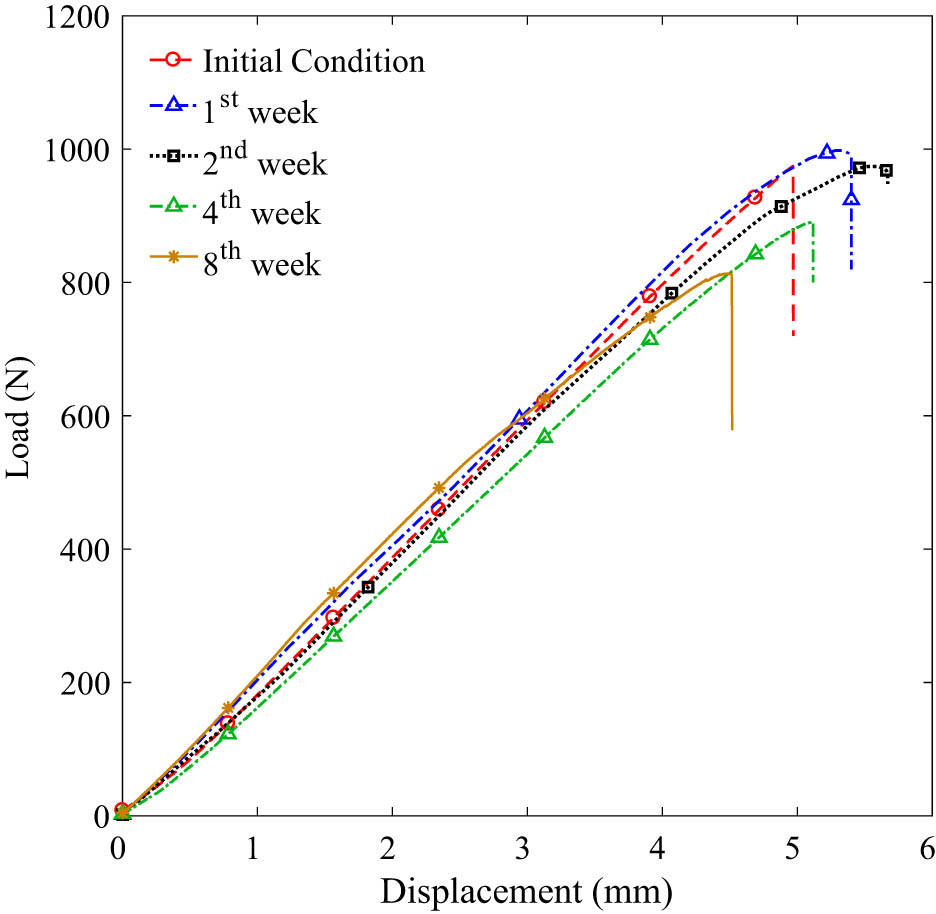
Load–displacement diagrams of specimens exposed to an acidic environment at 25°C.

Load–displacement diagrams of specimens exposed to an acidic environment at 90°C.
4.2 Fracture toughness
Figure 8 provides information about the mode II fracture toughness of the specimens aged at 25°C. According to the results, the fracture toughness increases after 1 week (from 2,200 to 2,447 J/m2) and increases to a peak of 3,187 J/m2 at the end of the second week. Nevertheless, the

Fracture toughness in mode II for samples exposed to an acidic environment at 25°C.
According to Figure 9, the fracture toughness decreases considerably from 2,200 to 1,680 J/m2 at the end of the 6th day. By the end of the 9th day, the fracture toughness experiences a sharp drop before it reaches 456 J/m2 at the end of the 12th day.

Mode II fracture toughness of samples exposed to an acidic environment at 90°C.
As mentioned earlier, by comparing the results of samples exposed to the acidic environment at 25 and 90°C, it can be concluded that the temperature accelerates the acid aging process in the acidic environmental conditions and cause a reduction in the mode II fracture toughness severely.
4.3 Numerical and experimental data comparison
By considering the flexural modulus

Numerical and experimental load–displacement curves of specimens exposed to the acidic solution at 25°C.
To obtain the flexural modulus, three-point bending tests were conducted on the samples after they were taken out of the acidic solution. This value was used as an input in the numerical analysis. According to Figure 11, the flexural modulus remained steady by the end of the first week and experienced a significant drop at the end of the second week. This value declined gradually until 8 weeks.

Flexural modulus as a function of different aging time at 25°C.
According to Figure 12, which represents the maximum load of specimens exposed to the acidic solution at 25°C, the maximum load increased considerably from 857.39 to 1028.95 N at the end of the second week and then declined substantially to the minimum amount of 803.40 at the end of the 8th week.

Maximum load of the samples exposed to an acidic environment at 25°C.
Figure 13 compares the experimental maximum load with the numerical results. Based on the results, at the end of the second week, the experimental maximum load was higher than the numerical one; nevertheless, at other conditions, it was lower.

Comparison of the maximum experimental and predicted loads for samples exposed to an acidic environment at 25°C.
Figure 14 presents the numerical load–displacement based on the flexural modulus obtained from the experimental results for samples exposed to the acidic solution at 90°C for 3, 6, 9, and 12 days. The slope of the load–displacement curves changes more sharply, and a considerable decline is seen in the maximum load, which is more noticeable after 6 days due to changes in the flexural modulus of the tested samples.

Numerical and experimental load–displacement curves of specimens exposed to an acidic solution at 90°C.
According to Figure 15, which shows the flexural modulus for different aging times, after 3 days of aging, a sharp drop in the flexural modulus occurs, and then, there is no significant change until the 6th day. After 9 days of the application of environmental conditions, the reduction in the flexural modulus is more noticeable.

Flexural modulus of the samples exposed to an acidic environment at 90°C.
According to Figure 16, the maximum load obtained from the numerical analysis correspond to the experimental results for samples subjected to the acidic solution at 90°C decreases by aging time. Based on the experimental and numerical results from Figure 17, the maximum load of the samples exposed to the acidic environment at 90°C declines in both approaches. The maximum load obtained by the experimental approach was higher in comparison with the numerical results; nevertheless, it was lower at the end of the 12th day.

Maximum load of samples exposed to an acidic solution at 90°C.

Comparison of the maximum experimental and predicted loads for samples exposed to an acidic environment at 90°C.
5 Conclusion
In this article, the effect of environmental conditions on mode II fracture toughness of E-glass/vinyl ester composites with the
-
Conflict of interest: Authors state no conflict of interest.
References
[1] Lyashenko‐Miller T, Marom G. Delamination fracture toughness of UHMWPE fibers/polyurethane laminates interleaved with carbon nanotube‐reinforced polyurethane films. Polym Adv Technol. 2017;28(5):606–12.10.1002/pat.3848Search in Google Scholar
[2] Marques J, Barbosa A, da Silva C, Carbas R, da Silva L. An overview of manufacturing functionally graded adhesives–challenges and prospects. J Adhes. 2019;97(2):172–206.10.1080/00218464.2019.1646647Search in Google Scholar
[3] Banks-Sills L, Simon I, Chocron T. Multi-directional composite laminates: fatigue delamination propagation in mode I – a comparison. Int J Fract. 2019;219(2):175–85.10.1007/s10704-019-00388-4Search in Google Scholar
[4] Karnati SR, Shivakumar K. Limited input Benzeggagh and Kenane delamination failure criterion for mixed-mode loaded fiber reinforced composite laminates. Int J Fract. 2020;222(1):221–30.10.1007/s10704-019-00418-1Search in Google Scholar
[5] Shang X, Marques E, Machado J, Carbas R, Jiang D, da Silva L. Review on techniques to improve the strength of adhesive joints with composite adherends. Compos Part B Eng. 2019;177:107363.10.1016/j.compositesb.2019.107363Search in Google Scholar
[6] Shang X, Marques E, Machado J, Carbas R, Jiang D, da Silva L. A strategy to reduce delamination of adhesive joints with composite substrates. Proc Inst Mech Eng Part L J Mater Des Appl. 2019;233(3):521–30.10.1177/1464420718805712Search in Google Scholar
[7] Hashemi S, Kinloch A, Williams J. The effects of geometry, rate and temperature on the mode I, mode II and mixed-mode I/II interlaminar fracture of carbon-fibre/poly (ether-ether ketone) composites. J Compos Mater. 1990;24(9):918–56.10.1177/002199839002400902Search in Google Scholar
[8] Tesinova P. Advances in composite materials: analysis of natural and man-made materials. Croatia: InTech; 2011.10.5772/728Search in Google Scholar
[9] MAROM G. Environmental effects on fracture mechanical properties of polymer composites. Compos Mater Ser. 1989;6:397–424.10.1016/B978-0-444-87286-9.50014-0Search in Google Scholar
[10] Ayatollahi MR, Ajdani A, Akhavan-Safar A, da Silva L. Effect of notch length and pre-crack size on mode II fracture energy of brittle adhesives. Eng Fract Mech. 2019;212:123–35.10.1016/j.engfracmech.2019.03.024Search in Google Scholar
[11] Pagano NJ, Schoeppner GA. Delamination of polymer matrix composites: problems and assessment. In: Anthony K, Carl Z, editors. Comprehensive composite materials. Pergamon: Elsevier; 2000. pp. 433–528. ISBN 9780080429939.10.1016/B0-08-042993-9/00073-5Search in Google Scholar
[12] Pochiraju KV, Tandon GP, Schoeppner GA. Long-term durability of polymeric matrix composites. New York, USA: Springer Science & Business Media; 2011.10.1007/978-1-4419-9308-3Search in Google Scholar
[13] Martin R. Ageing of composites. Cambridge, England: Woodhead Publishing Limited; 2008.10.1533/9781845694937Search in Google Scholar
[14] Zenasni R, Bachir A, Vinã I, Arguelles A, Viña J. Effect of hygrothermomechanical aging on the interlaminar fracture behavior of woven fabric fiber/PEI composite materials. J Thermoplast Compos Mater. 2006;19(4):385–98.10.1177/0892705706059743Search in Google Scholar
[15] Zenasni R, Bachir A, Garcia M, Argüelles A, Vina J. Hygrothermal aging effect on the interlaminar fracture of woven fabric fibre/PEI composite material. Sci Eng Compos Mater. 2004;11(4):225–30.10.1515/SECM.2004.11.4.225Search in Google Scholar
[16] Zhao Y, Liu W, Seah LK, Chai GB. Delamination growth behavior of a woven E-glass/bismaleimide composite in seawater environment. Compos Part B Eng. 2016;106:332–43.10.1016/j.compositesb.2016.09.045Search in Google Scholar
[17] Scida D, Aboura Z, Benzeggagh M. The effect of ageing on the damage events in woven-fibre composite materials under different loading conditions. Compos Sci Technol. 2002;62(4):551–7.10.1016/S0266-3538(01)00147-6Search in Google Scholar
[18] Srivastava V, Hogg P. Moisture effects on the toughness, mode-I and mode-II of particles filled quasi-isotropic glass–fibre reinforced polyester resin composites. J Mater Sci. 1998;33(5):1129–36.10.1023/A:1004305104964Search in Google Scholar
[19] Selzer R, Friedrich K. Inluence of water up-take on interlaminar fracture properties of carbon fibre-reinforced polymer composites. J Mater Sci. 1995;30(2):334–8.10.1007/BF00354392Search in Google Scholar
[20] Allnex. Hetron 922 vinyl ester resin technical data sheets: Allnex the coating resin company. Allnex Company; 2020. Available from: https://allnex.com/en/product/da649a6c-a2cf-41af-b28e-49e88affdcf8/hetron-922Search in Google Scholar
[21] SDYM F543-20. Standard practices for evaluating the resistance of plastics to chemical reagents. USA: ASTM International.Search in Google Scholar
[22] ASTM. D7905/D7905M–14. Standard test method for determination of the mode II interlaminar fracture toughness of unidirectional fiber-reinforced polymer matrix composites. USA: ASTM International; 2014. p. 20.Search in Google Scholar
[23] Akhavan‐Safar A, Salamat‐talab M, Ajdani A, Ayatollahi MR, da Silva LF. Mode II fracture energy characterization of brittle adhesives using compliance calibration method. Fatigue Fract Eng Mater Struct. 2020;43(9):1928–37.10.1111/ffe.13244Search in Google Scholar
[24] Dimitri R, Trullo M, De Lorenzis L, Zavarise G. Coupled cohesive zone models for mixed-mode fracture: a comparative study. Eng Fract Mech. 2015;148:145–79.10.1016/j.engfracmech.2015.09.029Search in Google Scholar
[25] Dimitri R, Trullo M, Zavarise G, De Lorenzis L. A consistency assessment of coupled cohesive zone models for mixed-mode debonding problems. Frattura Ed Integrità Strutturale. 2014;8(29):266–83.10.3221/IGF-ESIS.29.23Search in Google Scholar
[26] Dimitri R, Cornetti P, Mantič V, Trullo M, De Lorenzis L. Mode-I debonding of a double cantilever beam: a comparison between cohesive crack modeling and finite fracture mechanics. Int J Solids Struct. 2017;124:57–72.10.1016/j.ijsolstr.2017.06.007Search in Google Scholar
[27] Salamat-Talab M, Shokrieh M, Mohaghegh M. On the R-curve and cohesive law of glass/epoxy end-notch flexure specimens with 0//θ interface fiber angles. Polym Test. 2021;93:106992.10.1016/j.polymertesting.2020.106992Search in Google Scholar
[28] Campilho RD, Banea MD, Neto J, da Silva LF. Modelling adhesive joints with cohesive zone models: effect of the cohesive law shape of the adhesive layer. Int J Adhes Adhes. 2013;44:48–56.10.1016/j.ijadhadh.2013.02.006Search in Google Scholar
[29] Huang G, Sun H. Effect of water absorption on the mechanical properties of glass/polyester composites. Mater Des. 2007;28(5):1647–50.10.1016/j.matdes.2006.03.014Search in Google Scholar
© 2021 Mazaher Salamt-Talab et al., published by De Gruyter
This work is licensed under the Creative Commons Attribution 4.0 International License.
Articles in the same Issue
- Effects of Material Constructions on Supersonic Flutter Characteristics for Composite Rectangular Plates Reinforced with Carbon Nano-structures
- Processing of Hollow Glass Microspheres (HGM) filled Epoxy Syntactic Foam Composites with improved Structural Characteristics
- Investigation on the anti-penetration performance of the steel/nylon sandwich plate
- Flexural bearing capacity and failure mechanism of CFRP-aluminum laminate beam with double-channel cross-section
- In-Plane Permeability Measurement of Biaxial Woven Fabrics by 2D-Radial Flow Method
- Regular Articles
- Real time defect detection during composite layup via Tactile Shape Sensing
- Mechanical and durability properties of GFRP bars exposed to aggressive solution environments
- Cushioning energy absorption of paper corrugation tubes with regular polygonal cross-section under axial static compression
- An investigation on the degradation behaviors of Mg wires/PLA composite for bone fixation implants: influence of wire content and load mode
- Compressive bearing capacity and failure mechanism of CFRP–aluminum laminate column with single-channel cross section
- Self-Fibers Compacting Concrete Properties Reinforced with Propylene Fibers
- Study on the fabrication of in-situ TiB2/Al composite by electroslag melting
- Characterization and Comparison Research on Composite of Alluvial Clayey Soil Modified with Fine Aggregates of Construction Waste and Fly Ash
- Axial and lateral stiffness of spherical self-balancing fiber reinforced rubber pipes under internal pressure
- Influence of technical parameters on the structure of annular axis braided preforms
- Nano titanium oxide for modifying water physical property and acid-resistance of alluvial soil in Yangtze River estuary
- Modified Halpin–Tsai equation for predicting interfacial effect in water diffusion process
- Experimental research on effect of opening configuration and reinforcement method on buckling and strength analyses of spar web made of composite material
- Photoluminescence characteristics and energy transfer phenomena in Ce3+-doped YVO4 single crystal
- Influence of fiber type on mechanical properties of lightweight cement-based composites
- Mechanical and fracture properties of steel fiber-reinforced geopolymer concrete
- Handcrafted digital light processing apparatus for additively manufacturing oral-prosthesis targeted nano-ceramic resin composites
- 3D printing path planning algorithm for thin walled and complex devices
- Material-removing machining wastes as a filler of a polymer concrete (industrial chips as a filler of a polymer concrete)
- The electrochemical performance and modification mechanism of the corrosion inhibitor on concrete
- Evaluation of the applicability of different viscoelasticity constitutive models in bamboo scrimber short-term tensile creep property research
- Experimental and microstructure analysis of the penetration resistance of composite structures
- Ultrasensitive analysis of SW-BNNT with an extra attached mass
- Active vibration suppression of wind turbine blades integrated with piezoelectric sensors
- Delamination properties and in situ damage monitoring of z-pinned carbon fiber/epoxy composites
- Analysis of the influence of asymmetric geological conditions on stability of high arch dam
- Measurement and simulation validation of numerical model parameters of fresh concrete
- Tuning the through-thickness orientation of 1D nanocarbons to enhance the electrical conductivity and ILSS of hierarchical CFRP composites
- Performance improvements of a short glass fiber-reinforced PA66 composite
- Investigation on the acoustic properties of structural gradient 316L stainless steel hollow spheres composites
- Experimental studies on the dynamic viscoelastic properties of basalt fiber-reinforced asphalt mixtures
- Hot deformation behavior of nano-Al2O3-dispersion-strengthened Cu20W composite
- Synthesize and characterization of conductive nano silver/graphene oxide composites
- Analysis and optimization of mechanical properties of recycled concrete based on aggregate characteristics
- Synthesis and characterization of polyurethane–polysiloxane block copolymers modified by α,ω-hydroxyalkyl polysiloxanes with methacrylate side chain
- Buckling analysis of thin-walled metal liner of cylindrical composite overwrapped pressure vessels with depressions after autofrettage processing
- Use of polypropylene fibres to increase the resistance of reinforcement to chloride corrosion in concretes
- Oblique penetration mechanism of hybrid composite laminates
- Comparative study between dry and wet properties of thermoplastic PA6/PP novel matrix-based carbon fibre composites
- Experimental study on the low-velocity impact failure mechanism of foam core sandwich panels with shape memory alloy hybrid face-sheets
- Preparation, optical properties, and thermal stability of polyvinyl butyral composite films containing core (lanthanum hexaboride)–shell (titanium dioxide)-structured nanoparticles
- Research on the size effect of roughness on rock uniaxial compressive strength and characteristic strength
- Research on the mechanical model of cord-reinforced air spring with winding formation
- Experimental study on the influence of mixing time on concrete performance under different mixing modes
- A continuum damage model for fatigue life prediction of 2.5D woven composites
- Investigation of the influence of recyclate content on Poisson number of composites
- A hard-core soft-shell model for vibration condition of fresh concrete based on low water-cement ratio concrete
- Retraction
- Thermal and mechanical characteristics of cement nanocomposites
- Influence of class F fly ash and silica nano-micro powder on water permeability and thermal properties of high performance cementitious composites
- Effects of fly ash and cement content on rheological, mechanical, and transport properties of high-performance self-compacting concrete
- Erratum
- Inverse analysis of concrete meso-constitutive model parameters considering aggregate size effect
- Special Issue: MDA 2020
- Comparison of the shear behavior in graphite-epoxy composites evaluated by means of biaxial test and off-axis tension test
- Photosynthetic textile biocomposites: Using laboratory testing and digital fabrication to develop flexible living building materials
- Study of gypsum composites with fine solid aggregates at elevated temperatures
- Optimization for drilling process of metal-composite aeronautical structures
- Engineering of composite materials made of epoxy resins modified with recycled fine aggregate
- Evaluation of carbon fiber reinforced polymer – CFRP – machining by applying industrial robots
- Experimental and analytical study of bio-based epoxy composite materials for strengthening reinforced concrete structures
- Environmental effects on mode II fracture toughness of unidirectional E-glass/vinyl ester laminated composites
- Special Issue: NCM4EA
- Effect and mechanism of different excitation modes on the activities of the recycled brick micropowder