Automated, Quality Assured and High Volume Oriented Production of Fiber Metal Laminates (FML) for the Next Generation of Passenger Aircraft Fuselage Shells
-
Hakan Ucan
 ,
Joachim Scheller
,
Joachim Scheller

Abstract
The use of fiber-metal laminates (FML) allows for substantial advantages over a fuselage skin made of monolithic aluminum materials. Glass fiber prepreg reinforced aluminium is characterized by high damage tolerance capabilities, supporting the structural strength capability in case of any kind of damage. For this reason, FML, and GLARE in particular, have been identified as superior materials for aerospace applications. More than 400m2 FML is applied on each A380, as skin panels and as D-noses for both, vertical and horizontal stabilizer. FML possess the potential to become the baseline material for next-generation single-aisle aircrafts [1, 2, 6].
The development of a new production chain that will allow automated fuselage production for future short-haul aircrafts is the focus of the studies that make up the joint project AUTOGLARE. As part of the fifth call-up for the German Aeronautical Research Programme (LuFo), the German Aerospace Center (DLR) is working with its project partners Airbus Operations, Premium Aerotech (PAG) and the Fraunhofer Gesellschaft (FhG). The development of a production chain for stiffened fuselage panels made of Fiber metal Laminates should support a production rate of 60 aircraft per month [3].
This study contains the research work of the DLR and FhG regarding the automated and quality assured process for chain stiffened FML fuselages. In addition to a detailed explanation of the systems that were set up, this paper covers the planned tests, the completed demonstration models and the findings derived from them.
1 Introduction and state of the art
Thanks to the multiple load path character of the FML concept, the structural capability of fuselage shells designed with the low cost alloy 2024 could be improved significantly. The GLARE fuselage panels, which are applied on the A380, which are applied on the A380, fulfill and exceed all OEM targets, e.g. significant weight saving, damage arrest capability and no demand for scheduled fatigue inspections. The damage tolerance capability of the FML furthermore provides more flexibility in cases of manufacturing concessions and concerning repairs in service [4]. Within fourteen years after first flight, no single complaint about the structural GLARE performance is received from the A/C operator.
The process chain for FML skin sections was an exclusively manual part of the A380 program. It is used at Premium Aerotech in Nordenham (Germany) and Fokker Technologies in Pappendrecht (NL) and is based on the concept of curing stiffened panels twice in an autoclave (multi-shot bonding). First, the skin panel, consisting of aluminum and glass-fiber prepreg is processed. The cured skin section is then cured again, together with the stiffening
elements required to reinforce the structure. This is time-consuming and costly [5].
Each A380 contains 440 m2 of FML in the fuselage panels and as part of the horizontal- and vertical stabilizer leading edges - an area almost equal to the surface of the A320 pressurized fuselage. Both, the structural details and the production volume for an A380 and for a narrow body are quite different. For a production rate of more than 50 A/C per month automated manufacturing is mandatory, whereas investment in automated FML lay-up does not pay off for low volumes. Details about the development of automated FML manufacturing are provided in the following chapters of this report. As a result, it can be said: automated manufacturing allows for fuselages with 2024-FML shells for similar costs as for the established riveted, monolithic 2024 structures [6].
2 Automated placement of aluminium foils
The process for aluminum foil lay-up has to meet several requirements. Damage-free handling and transport as wellas accurate positioning are vital to the quality of the resulting part. Three-dimensional geometries offer special challenges for the procedure. The lay-up of plane aluminum sheets on spherical surfaces can induce inner stresses into the resulting part. This ultimately limits the size of plane aluminum sheets that can be placed in a spherical mold. Preliminary investigations are conducted to identify the maximum size of flat sheets that can be used for a pick and place process without buckling of the aluminum under vacuum. The size of the sheets is subject to the local curvature radius of the mold [7].
Those trials identified boundary conditions regarding size and geometry of the aluminum cut-pieces and lead to several requirements for the end-effector design. It incorporates eight linear actors that allow for adjustment to different curvatures as well as pneumatic brakes that enhance the stiffness during lay-up. The angular values for the adjustment of the end-effector are determined from the CAD-data of the part. Grip-points are generated automatically with a software tool. Once the end-effectors are adjusted the aluminum can be picked up from a flat surface in a rolling motion (see Figure 1).
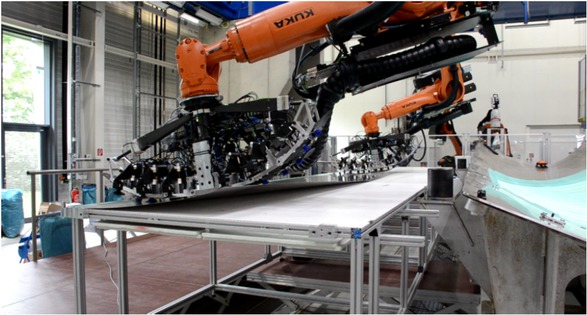
Pick-up of plane aluminum foils with cooperating robots © DLR
For a demonstrator of 7 m x 2 m size a total of 15 aluminum sheets are automatically placed by cooperating robots in the multifunctional robot cell at DLR in Augsburg. Three types of sheets can be distinguished: longitudinal sheets with a maximum length of 5800 mm, circumferential sheets with a maximum size of 2200 mm x 850 mm and splice straps which are up to 5800 mm in length but only
150 mm wide. The aluminum can be handled without damaging the sheets. An accuracy of ±2 mm can be achieved in cylindrical areas. In spherical areas the position of the cut-pieces exhibits deviations of up to 10 mm from the ideal values. This can be explained with the discrepancy between the plane foils and the 3D geometry of the mold. The correct lay-up will have to be verified after curing to ensure the quality of the resulting part. In general, larger sheets (i.e. longitudinal plies) can be handled more easily as the grip points of the robots are further apart. This lowers the risk of collision between the robots and simplifies the programming of the process. Curling of the sheets in the spherical area of the mold is visible before but not after vacuum is applied to the lay-up.Hence, the dimensions of the sheets are sufficient for the given mold but close to the maximum size at which bends will occur under vacuum and remain in the cured part. Measurement of the induced stresses via strain gauges attached to the part during vacuum and curing cycle will be the next step to verify the maximum size of the sheets.
2.1 Quality Assurance in Aluminum Foil Lay-Up Processes
In order to guarantee placement of the aluminum foils within tolerances and to increase confidence in the process, inline quality assurance (QA) measures are necessary. A laser triangulation sensor (LLS) has been selected to verify the correct foil lay-up. Information about the mold geometry and the expected contour of the plies are extracted from CAD (plybook) and used to generate paths for the LLS end-effector. Mounted on a robot, the scanner is guided along the cut-piece edges with a measurement range of ± 50 mm (see Figure 2, left). It generates a 3D unstructured point cloud with a resolution of 0.15 mm point to point distance on one scan line and 0.5 mm distance between individual lines (see Figure 2 top right). The LLS is monitored with a laser tracker. This system can determine the position of the end-effector with an accuracy of approximately ± 60 μm and thus exclude the tolerance of the robot movement from the error chain.
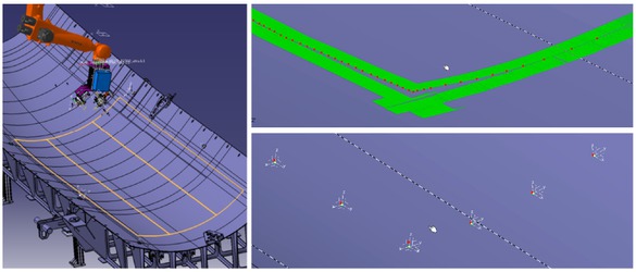
Edge detection with LLS in the virtual environment of the MFZ, © DLR
In order to detect the cut-piece edges, points along the edge are marked and connected to a closed line contour. For a significant target-actual comparison one approach is to discretize the contour between the edges of the cut-piece. Such comparison points are shown in Figure 2 (bottom right) as green dots for the target contour and as red dots for the actual contour. Local coordinate systems are placed at each target dot and the deviations can be plotted for each axis. Deviations that can be detected are: undulation in z-direction, elongation as well as compression in y-direction, and wrong position in x-direction. In principle, the detection of the edge points as well as the connection to form the actual contour can be done manually. Automation via algorithm is feasible and currently under implementation.
3 Automated placement of glass prepregs
Nowadays, FML are parts mostly manufactured manually by workers, which results in high production times and non-reproducible part quality. If this material is to be used for the next generation short range aircraft with up to 60 units per month, an automation of the manufacturing process to increase the productivity is necessary [8].
For this reason, the layup of glass fiber prepreg material with automated placement technologies like Automated Tape Laying (ATL) or Automated Fiber Placement (AFP) were tested at the DLR research platform Grofir in Stade. Both technologies are investigated regarding processibility and layup behavior along a curved path (steering [1]).
Results show that the material can be processed with both technologies, ATL and AFP. With layup speeds of up to 12 m/min, the material can be laid up with sufficient tack and free of defects like problems with cutting. Different results can be observed regarding steering. For ATL, steering is not possible for radii of 30 m or lower as wrinkles cannot be avoided. The reason for this is the high width of the material of 150 mm, which limits its draping behavior. In contrast to that, steering radii down to 6 m can be achieved with AFP technology, where 16 tows with a width of 6.35 mm each are laid up. Therefore the draping capability is much higher compared to material for ATL.
Finally, both technologies are validated by the manufacturing of two fuselage skin demonstrator (Figure 3). Because of the preliminary tests, the ATL demonstrators are manufactured with overlap of the glass fiber material, while the AFP demonstrator are manufactured with steering and therefore without gaps or overlaps.
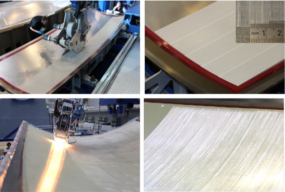
Manufacturing of double curved fuselage skin demonstrators with placement technologies ATL (top) and AFP (bottom) in DLRs research platform Grofir, Stade, © DLR
3.1 Quality Assurance in Glass Prepreg Lay-Up Processes
Currently, part inspection takes up to 68% of overall production time. The goal within this project is the enhancement of an existing inline inspection system. Inside the project AUTOGLARE, the approach includes concept design, development and implementation of feasible feature extraction algorithms for machine learning, as well as integration and validation during fiber layup. A cascadian analysis structure is developed which contains the rapid defect detection for data reduction, feature extraction in combination with classification by a support vector machine and defect measurement [9, 10].
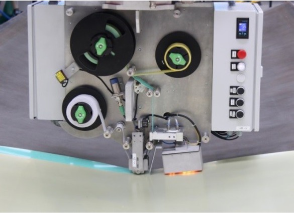
The usage of the system during a fiber placement process is shown in Figure 4. The laser light section sensor scans the layup surface and uses depth and reflection information as input for defect detection and classification.
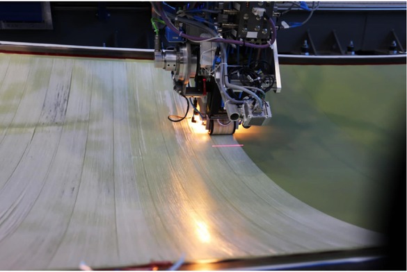
Laser light section sensor mounted to an automated fiber placement head, © DLR
The results of defect detection and classification are visualized in false colours in Figure 5. Two twist defects in a fiber layup are shown exemplary.
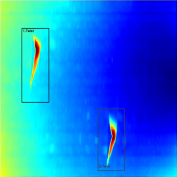
Two twist defects upon a fiber layup colorized in false colours, © DLR
The improved system is able to process data in the defect detection step within an average calculation time of 91.0 ms with standard deviation of σ = 5.6 ms. The average detection rate is 99.1% with a standard deviation of σ = 1,3%.
4 High-precision placement of adhesion films and stringers
After each placed layer of aluminum foil, the application of adhesive strips is necessary to ensure a bonding to the next overlapping foil. Also, each stringer has to be bonded to the top layer. To apply the adhesive strips on all possible positions, an end effector needed to be designed, which is mounted to an industrial robot on a linear axis. The following major requirements had to be fulfilled by the end effector: 1. Mounting adhesive roller and guiding adhesive strips; 2. Monitoring laid length of adhesive strip; 3. Calculation of remaining adhesive on roller; 4. Constant strip tension; 5. Increased tack of adhesive strip on the aluminum foil; 6. length accuracy: ±1 mm; straightness: ±1 mm; gap: −0,5 mm to +1 mm; 7. Layup speed: 10 m/min; 8. Length of strips: 1 cm to 12 m. Figure 6 shows the developed adhesive end effector with the components, which are necessary for the solutions of the major requirements.
Solutions for the requirements of an adhesive end effector, © Fraunhofer Gesellschaft
The adhesive strip is guided through the end effector without any contact to deflection rollers; only the backing paper and liner are in contact with them. The cardboard core of the adhesive roller is clamped onto the end effector by spreading the mounting roller (solution for requirement 1). For requirement 2 and 3, an incremental encoder on one of the deflection rollers calculates the laid adhesive film by rotation. Together with the measured diameter of the adhesive roller, the remaining adhesive can be calculated by equation (1)[2].
The tension of the adhesive is maintained by two mechanisms. First, the target torque is calculated for the servo motor of the adhesive roller with the entered tension and the current radius of the roller. Second, the incremental encoder works as a master for the backing paper roller (slave), which rotates until the target position is reached (requirement 4). For requirement 5 an infrared heater heats the aluminum foil to increase the tack of the adhesive film, when it reaches the heated position. This mechanism is done constantly throughout the process to ensure a higher tack to the aluminum than to the backing paper. Furthermore, the accuracy is achieved by compact design with height of 600 mm, low weight of 75 kg and an accurate offiine programming of paths (requirement 6). This fundamentals combined with strong servo motors allow lay up speed of more than 13 m/min (requirement 7). The end effector is capable of cutting, placing, and pressing down double-sided adhesive tapes of any length from a few millimeters up to 50 meters onto flat, curved, and double curved surfaces (requirement 8). With slight modification the end effector can be used for the precision placement of other types of materials on other component surfaces.
4.1 Integration of 6 Meter Long Stringers Using Cooperating Robots
In current aircraft production, stringers can size up to 12 meters. For such long stringers the deformation behavior needs to be taken into account. Furthermore, to grip a variety of stringer profiles, a system with two grippers was developed, each fitted to its own robot. One gripper fixes the stringer, and one integrates the stringer onto the skin field. For the handling, one robot follows the path of the other robot at a defined distance. The grippers automatically adapt to the length as well as the thickness of the stringer and therefore can grip stringers of differing geometries. The heating of the adhesive film under the stringer, the contact pressure, and the integration speed can be varied for each process. For quality assurance purposes all parameters are recorded. The grippers compensate unevenness in the stringers, thus ensuring integration within the force and temperature specifications. 6 meter long stringers can be integrated with an accuracy of ±2mm on double-curved surfaces.
5 Curing with inline QA
When using industrial processing mediums for curing, such as an autoclave, extended cure cycles which are reducing the productivity and increasing the costs are state of the art. To avoid these extra expenses and to ensure the part quality, inline quality assurance and process simulation tools are developed at DLR [11].
5.1 One-Shot-Bonding and Optimized Autoclave Processes
In the DLR One-Shot-Bonding approach [3]the stringers are integrated onto the uncured part and bonded in the same autoclave cycle in which the actual curing of the skin laminate takes place. This eliminates the second autoclave cycle and enables a shorter production time. At the same time, the complexity of the vacuum bagging increases for the One-Shot-Bonding process, which calls for improved quality assurance.At DLR, flow measurement and infrared thermography are used to identify leakages in the bagging before and during the autoclave cycle.
To further optimize the autoclave cycle a curing simulation is used.With this simulation it is possible to identify cold and hot spots in the part (see lefthand side of Figure 7) and to find the best placement of the tooling inside the autoclave in order to achieve the best temperature distribution inside the part. The curing behavior of the material is analyzed and the resulting material model is implemented into the simulation, alongside the part and tool geometry. The first step is to simulate the standard curing process as given by the material supplier. As specific temperature tolerances need to be ensured, the curing cycle is extended and thus longer than the actual curing of the material requires. To optimize the process, a curing cycle depending on the degree of cure of the material is simulated. The target degree of cure is set to ≥ 95% in the coldest area of the part, which leads to a process time reduction of 27% from 199 min to 146 min. In the second step the heating rate is optimized to a steeper heating of the air (from 2 K/min to 2,8 K/min) which still ensures a heating rate of 2 K/min inside of the material, as suggested by the material supplier. This improvement leads to another process time reduction of 8min so that a total process time reduction of 30% is achieved in the simulation.
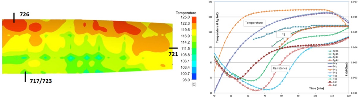
Simulated cold and hot spots areas (left), sensor data from the DEA (right), © DLR
The simulated curing cycle is tested on the demonstrator part. A comparison of the simulated and real process data shows a small deviation during the heating of the part. This deviation shows some room for improvement in the simulation, which needs to be considered when using the simulation for further process improvement. Altogether, the demonstrator showed that a process time improvement of 20% can be achieved.
5.2 Cure Monitoring by DC Dielectric Sensors
To detect the on-going degree of cure of FML laminates in situ, dielectric flexible sensors are introduced into the laminate. These sensors must be in touch with the resin during the entire cycle and can measure the resistivity and the temperature of the resin. The resistivity changes with the resin’s viscosity and can be correlated to the degree of cure and the glass transition temperature of the laminate. The most critical locations to place the sensors are revealed through simulation and four sensors are integrated into the laminate at different cold and hot spots as shown in Figure 7.
Preliminary trials showed the functionality of the sensors in the industrial environment. The final demonstrator confirms the potential of this sensor technology to save curing time, as the process targets is already achieved after 50% of the recommended cycle time, and the cycle thus terminated.
5.3 Strain Measurement by Fiber-Bragg-Gratings and Strain Gages
From an FML design point of view, the so-called stress-free temperature Tsf is of particular importance, as it directly relates to the material’s residual stress state after manufacturing, which determines the load bearing capacity of the final part. Tsf denotes the moment/temperature during the manufacturing process, where a permanent, sustainable load-bearing connection between the curing prepreg layers and the metal foils is established. Therefrom, an application of the classical laminate theory allows for calculation the manufacturing-related residual stress state in the material, based on the effective cooldown temperature of ᐃT = Tambient − Tsf . Within the AUTOGLARE project, a bipath measurement concept has been pursued to monitor the evolving residual-stress state within the FML along the entire 125°C, 11bar curing process. Fiber-Bragg-gratings (FBG) and strain gages (SG) were used simultaneously to measure strains in the curing composite layers and the thin metal foils, respectively, at the same time (see Figure 8a). A study has been successfully conducted in the project, to validate the SG and FBG measurement techniques and to validate the specific temperature compensation factors,whichwere determined for the optical sensors in previous investigations [12].
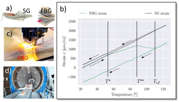
In-situ strain measurement using FBG and strain gages during autoclave processing
A FML 3 3/2 laminate, with 0.3 mm thick anodized 2024 aluminum layers, manufactured on an aluminum tool, serves as reference specimen. It is instrumented with a SG on the top aluminum layer and an FBG aligned in fiber direction of the first glass-fiber-prepreg layer, in between the upper prepreg layers. The obtained strain signals are shown in Figure 8b. Both signals show a linear strain-temperature relation right from the beginning. At specimen temperatures of 55°C and 87°C, the FBG signal shows kinks, related to viscosity decrease and volumetric chemical shrinkage of the epoxy resin. The SG shows a linear thermo-elastic behavior of the aluminum layer. At temperature above 110°C both signals show identical linear slopes,which indicates that the material acts as cured composite material, which refers to the definition of the stress-free temperature Tsf . After validating the measurement infrastructure on laboratory scale, it is transferred to an industrial scale, by integrating FBGs into an automated-fiber placement process (AFP, see Figure 8c). Robust data acquisition is observed during the manufacturing of a full-scale FML demonstrator (see Figure 8d). The demonstrated ability to measure Tsf directly, on an industrial scale is considered the prerequisite for the development of smart-cure-cycles, which help to shorten manufacturing processes to the necessary length, which can lead to considerable cost savings in the future.
6 Conclusion
This paper summarizes the work carried out, the planned experiments, the demonstration models manufactured and the key results in the joint project AUTOGLARE. It has been shown that concepts and technology from the R&T baseline yielded promising results in terms of the project objectives, in addition to the opportunities revealed by the production of demonstrator models.
Acknowledgement
The authors would like to thank the German Federal Ministry of Economic Affairs and Energy (BMWi) and the DLR Project Management Agency, who provided funding for this project, under the auspices of the second call for the fifth German Aeronautical Research Programme. They would also like to thank all the partners—Airbus Operations GmbH, Fokker Technologies, Stelia Aerospace, FFT EDAG, Hexcel and 3M—for the smooth collaboration.
References
[1] Beumler, T. 2004. ”Flying GLARE – A contribution to aircraft certification issues on strength properties in nondamaged and fatigue damaged GLARE structures”, PhD Thesis, Delft University of Technology, NetherlandsSearch in Google Scholar
[2] Alderliesten, R., C. 2017. “Fatigue and Fracture of Fibre Metal Laminates”, Springer International Publishing10.1007/978-3-319-56227-8Search in Google Scholar
[3] Apmann, H. 2016 "Automated FML Manufacturing for Aircraft Fuselages," SAE Int. J. Aerosp. 9(2):214-216,10.4271/2016-01-2112Search in Google Scholar
[4] Hombergsmeyer, E. 2006. “Development of advanced laminates for aircraft structures” presented at the ICAS Conference 2016, 3 - 8 September 2006, Hamburg, GermanySearch in Google Scholar
[5] Ucan, H. et al. 2018. “Production technologies for lightweight structuresmade from fibre–metal laminates in aircraft fuselages” in CEAS Aeronautical Journal (330), 1-11Search in Google Scholar
[6] Beumler, T., 2014. “Development of thin-walled FML structures” presented at the AEROMAT Conference, 16 - 19. June 2014, Orlando, USASearch in Google Scholar
[7] Deden, D., 2017. “Automated layup of spherical GLARE components using cooperating robots” presented at the SAMPE Europe 2017, 14.-16. Nov. 2017, Stuttgart, GermanySearch in Google Scholar
[8] Nguyen, C. Krombholz, C. Ucan. H. 2018 „Vergleich von Legetech-nologien für die automatisierte Glasfaserablage in der Glare-Bauteilfertigung“ presented at the German Aerospace Congress, 4.-6.Sept. 2018, Friedrichshafen, GermanySearch in Google Scholar
[9] Halbritter, A. & Harper, R., 2012. Big Parts Demand Big Changes to the Fiber. SME Composites Manufacturing.Search in Google Scholar
[10] Meister, S., 2017. Software for inline quality assurance within automated fibre layup processes, Stade: German Aerospace Center. DLR-Internal report. DLR-IB-FA-SD-2018-211Search in Google Scholar
[11] Liebers, N. Ucan, H. Kleineberg, M. Wiedemann, M. 2012. “Sensor and real-time-process-simulation guided autoclave process control for composite production” presented at the ICAS Conference 2012, 24. - 28. Sept. 2012, Brisbane, AustraliaSearch in Google Scholar
[12] Prussak, R. Stefaniak, D. Hühne, C. Sinapius, M., 2018, “Evaluation of residual stress development in FRP-metal hybrids using fiber Bragg grating sensors” in Production Engineering Springer, Issue 2/201810.1007/s11740-018-0793-4Search in Google Scholar
© 2019 H. Ucan et al., published by De Gruyter
This work is licensed under the Creative Commons Attribution 4.0 Public License.
Articles in the same Issue
- Analysis on the impact response of fiber-reinforced composite laminates: an emphasis on the FEM simulation
- Artificial neural network for predicting the flexural bond strength of FRP bars in concrete
- Cyclic behavior of GFRP strengthened infilled RC frames with low and normal strength concrete
- Durability of basalt fiber-reinforced polymer bars in wet-dry cycles alkali-salt corrosion
- Effect of B4C particle size on the mechanical properties of B4C reinforced aluminum matrix layered composite
- Enhanced dielectric properties of BaTiO3 ceramics with cerium doping, manganese doping and Ce-Mn co-doping
- Free and forced vibration analysis of rectangular/circular/annular plates made of carbon fiber-carbon nanotube-polymer hybrid composites
- Influence of nano-SiO2 on the bonding strength and wear resistance properties of polyurethane coating
- Investigation of wear behavior of nanoalumina and marble dust-reinforced dental composites
- Negative effect of clay fillers on the polyvinyl alcohol biodegradation: technical note
- Photocatalytic activity of Cu2O/ZnO nanocomposite for the decomposition of methyl orange under visible light irradiation
- Sub-surface mechanical properties and sub-surface creep behavior of wood-plastic composites reinforced by organoclay
- Surface integrity in wire-EDM tangential turning of in situ hybrid metal matrix composite A359/B4C/Al2O3
- The influence of the WC-Co composite microstructure model on stress field heterogeneity at the microstructure level: FEM based study
- Vibration-damping characterization of the basalt/epoxy composite laminates containing graphene nanopellets
- A review on nanocomposite hydrogels and their biomedical applications
- Optimization and simulation analysis of structure parameters of OPCM ultrasonic longitudinal wave actuating element
- Research Article
- Preparation of POSS-triol/wollastonite composite particles by Liquid phase mechanochemical method and its application in UV curable coatings
- Research on preload relaxation for composite pre-tightened tooth connections
- Dough moulding compound reinforced silicone rubber insulating composites using polymerized styrene butadiene rubber as a compatibilizer
- Hydration And Microstructure Of Astm Type I Cement Paste
- Effects of NiO content on the microstructure and mechanical properties of AgSnO2NiO composites
- Overall buckling behaviour of laminated CFRP tubes with off-axis ply orientation in axial compression
- UV sensing optode for composite materials environment monitoring
- On crushing characteristics of hybrid sandwich aluminum-cardboard panels reinforced with glass fiber composite rods
- Preparation and characterization of Ni-Cu composite nanoparticles for conductive paints
- A research on the preparation of oil-adsorbing hydrophobic porous resins by high internal phase emulsions (HIPEs) template
- Material characteristics of random glass-mat-reinforced thermoplastic under cryogenic thermal cycles
- Differentiation of non-black fillers in rubber composites using linear discriminant analysis of principal components
- Research Article
- Efficiency of TiO2 catalyst supported by modified waste fly ash during photodegradation of RR45 dye
- Synthesis and performance of polyurethane/silicon oxide nano-composite coatings
- Study on preparation of magnesium-rich composite coating and performance enhancement by graft modification of epoxy resin
- Research Article
- Mechanical and wear properties of polyetheretherketone composites filled with basalt fibres
- Mechanical Properties of Al 25 wt.% Cu Functionally Graded Material
- Research Article
- Weight reduction of a carbon fibre composite wheel
- Synthesis, electrical properties, and kinetic thermal analysis of polyaniline/ polyvinyl alcohol - magnetite nanocomposites film
- Seismic Behaviour of TRC-Strengthened RC Columns under Different Constraint Conditions
- Characterization of neat and modified asphalt binders and mixtures in relation to permanent deformation
- Microstructures, interface structure and room temperature tensile properties of magnesium materials reinforced by high content submicron SiCp
- Research Article
- Effect of Cutting Temperature on Bending Properties of Carbon Fibre Reinforced Plastics
- Mechanical and tribological properties of B-C-N coatings sliding against different wood balls
- Thermal conductivity of unidirectional composites consisting of randomly dispersed glass fibers and temperature-dependent polyethylene matrix
- Effects of Waste Eggshells addition on Microstructures, Mechanical and Tribological Properties of Green Metal Matrix Composite
- Investigation of porosity effect on flexural analysis of doubly curved FGM conoids
- Review Article
- Utilization of tailings in cement and concrete: A review
- Research Article
- Equivalent stiffness prediction and global buckling analysis using refined analytical model of composite laminated box beam
- Mechanochemical synthesis of zincite doped with cadmium in various amounts
- Size-dependent vibration analysis of graphene-PMMA lamina based on non-classical continuum theory
- Automated, Quality Assured and High Volume Oriented Production of Fiber Metal Laminates (FML) for the Next Generation of Passenger Aircraft Fuselage Shells
- Research Article
- An investigation of the stitching effect on single lap shear joints in laminated composites
- The low-velocity impact and compression after impact (CAI) behavior of foam core sandwich panels with shape memory alloy hybrid face-sheets
- Effect of granulometric distribution on electromagnetic shielding effectiveness for polymeric composite based on natural graphite
- The enhancement of filament winding in marine launching rubber gasbag
- Research on ELID Grinding Mechanism and Process Parameter Optimization of Aluminum-Based Diamond Composites for Electronic Packaging