Mechanical Properties of Al 25 wt.% Cu Functionally Graded Material
-
Aref Mehditabar


Abstract
The present work refers to describe the effects of Al2Cu variations on various properties of thick-walled functionally graded (FG) cylindrical shell. Al-25 wt.% Cu hypo-eutectic alloy ingot is melted and centrifugally casted to obtain high entropy FG composite. A series of microstructure examinations such as FESEM and EDX analysis were carried out to determine the distributions of constituent phases and elements. It is revealed that the maximum volume fraction of Al2Cu particle is reached near the inner surface with 35.7 Vol.% and then reduces gradually to 32.5 Vol.% at the outer surface of FG cylindrical shell. The effects of the variations Al2Cu along radial direction of FG tube are discussed through Vickers hardness, wear rate, coefficient of thermal expansion and compressive test measurements. The experimental results show that the wear and hardness are varied in graded manner which the highest wear resistance with wear rate of 9.1×10⁻⁵g/mm2 and hardness with 153HV are found towards Al2Cu enriched zone or inner periphery. Moreover, the studied FG cylindrical shell shows drop 2.5% in yield stress and 4.5% in elastic modulus from intermediate to inner layers due to Al2Cu particles clustering in metal matrix.
1 Introduction
The desire for long-term performance of structures in withstanding extreme temperature gradient through specific direction with maintaining integrity of the structure, has leaded in development of new class of advanced composite materials so-called functionally graded materials (FGMs). In this type of composite material, the properties are smoothly and continuously varied from one to the other surfaces by means of non-uniform distributions of reinforcement phase. Gradual changing of material properties along the specific direction, eliminates the corrosion, fatigue, fracture and local stress concentrations resulted from the abrupt changes of material properties in monolithic laminated composite material [1]. Accordingly, special processing is required to produce these smooth changes in properties in these kinds of materials. Several techniques for fabrication of FGMs components have been proposed such as melt processing, hot spraying duplicate, powder metallurgy, processing of polymer-based FGMs and etc. However, centrifugal casting method is the most efficient and affordable procedure that manufacturing can be performed with fewer processing steps.
Different alloying elements are applied to fabricate Al-based FGM, such as Al-Ti, Al-Ni-Ti, Al-Cu, Al-Cu-Fe, Al-Mg-B, Al-Ni and Al-Zr. Among various kinds of aluminummetal matrix, Al-Cu casting alloy as an important class of light-weight materials has been found widespread use in aircraft structures and other engineering areas. The other capabilities of Al-Al2Cu FG structure that can be mentioned are good specific strength and good wear resistance.
The microstructure formation is a key issue for understanding the behavior of FG materials. Therefore, a series of microstructure analysis are carried out to characterize the types of the phases and obtain the variations of constituent phases through thickness of FG tube. To accomplish these purposes, FESEM with aid of computer software (MATLAB code) that workson image analysis are employed to obtain the distributions of existing phases across the casting section. Until recently, many researches on FG Al-metal matrix fabricated through centrifugally casting method are carried out that are overviewed here. Duque et al. [2] investigated the microstructural behavior of FG Al-metal matrix reinforced with different volume fractions of AlB2 manufactured through centrifugal casting technique. Rajan et al. [3] processed FG Al (A356)200/0SiC and (A390) 200/0SiC by vertical centrifugal casting technique for composite brake discs in order to augment the efficiency of braking performance. Lin et al. [4] systematically studied the distributions of the volume fractions and particles sizes of Al-Si-Mg FGM tube reinforced with insitu Si/Mg2Si particles manufactured by centrifugal casting method. Al-19Si and Al-19Si-5Mg FG composites cylindrical shells weresuccessfully centrifugally casted by Yan-bo et al. [5]. In their research, distributions of microstructures, hardness and wear resistance for two kinds of FG tubes were compared and discussed. Wanatabe et al. [6] investigated the influences of process conditions such as G number and cast condition on the variations of microstructure and cooling rate in FG pipe made of Al-Al2Cu fabricated through centrifugal casting method. Wanatabe and Oike [7] carried out the microstructural study of Al-Al2Cu FGMs employing horizontal centrifugal casting method with different initial master ingots. In their work, three specimens from the initial master ingots for (1) Al-200/0Cu (hypoeutectic)(2) Al-330/0Cu (eutectic)(3) Al-400/0Cu (hypereutectic) were utilized. The influences of processing parameters including die speed and pouring temperature on mechanical properties of Al-Si alloy produced by centrifugal casting using Taguchi technique was investigated by Shailesh et al. [8]. Radhika and Raghu [9] applied various reinforcements for FGM Al-based master alloy to demonstrate the comparative study of graded properties through the hardness and abrasive wear tests using centrifugal casting technique. Chenet et al. [10] utilized centrifugal casting method to fabricate FG composite by Al-Zn-Si as elemental alloy to illustrate relation between microstructure distributions of the composite and hardness and wearresistance along radial direction. El-Hadad et al. [11] focused on the fabrication of Al-Al3Ti/Ti3Al using a unique method of centrifugal casting procedure. The consequence of processing temperature on size, shape and distributions of the reinforcement particles and their influences on hardness variations were shown. FGMs Cu-matrix tube reinforced with powder mixture of abrasive grains metal particles was successfully fabricated through centrifugal sintering-casting technique by Kunimine et al. [12]. Interaction between processing condition including sintering temperature, holding time and casting temperature and microstructure of specimens were examined. Soflaei and Vahdat [13] carried out microstructure evaluation bonding location and length determination of diffusion bond in bi-metal structure of steel-bronze. Vahdat [14] investigated the relation between particle size and volume fraction of intermetallic composition Cu6Sn5 on bulk hardness of SnCu4Pb3. A review of the available literatures and to the knowledge of the authors, there is vast potential for further research on development and optimization of Al-Cu FGM as main and most applicable alloy in various engineering fields specially in sensitive and important industry of aerial section.
In the present paper, Al-Al2Cu FGMs are prepared from Al-25 wt.% Cu alloy using the horizontal centrifugal casting method. After production processing, a series of microstructure at submicron scales including FESEM tests are performed to determine the distributions of intermetallic compounds across the casting section. Moreover, miscellaneous tests at macro scales are carried out to achieve variations of parameters such as Vickers Hardness, coefficient of thermal expansion, elastic modulus, yield strength and wear rate as function of position across the radial direction. The main object of this work is to connect graded distribution of Al2Cu particles on the variations of aforementioned properties of FGMat various locations across the thickness.
2 Material and Methods
In this work, horizontal centrifugal casting equipment is applied to fabricate thick-walled Al-Al2Cu FG cylindrical shell. A schematic representation of horizontal centrifugal casting system is illustrated in Fig.1.
Characterizations of machinery components are described as follows. Electromotor 0.55 KW manufactured by DUTCHI NL company accompanied with convertor 200 V fabricated by TECO E310 company series were applied to regulate the rotational speed of mold. Steel is considered for material of mold and also geometrical properties of mold are assumed to be 12mm in thickness (t), 240 mm in length (L) and 100 mm in inner diameter (D) with L/D equals to 1.2.
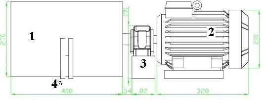
Schematic diagram of horizontal centrifugal casting applied for fabricating Al-Al2Cu FGM, all dimension in millimeter
Al-25 wt.% Cu with the chemical compositions listed in Table 1 were utilized for the production of Al-Al2Cu FG tube.
Chemical composition of FGM ingot
| Element | Al | Cu | Si | P | S | K | Ca | Zn |
|---|---|---|---|---|---|---|---|---|
| Wt.% | Balance | 25.248 | 6.228 | 0.034 | 0.110 | 0.657 | 0.374 | 0.160 |
5 kg of commercial pure Cu ingot and 17 kg of commercial Al ingot with 8.2 wt.% of Si and 2.3 wt.% of Cu as major alloy element were taken as raw materials. As first step towards producing centrifugally casted Al-Al2Cu FGM, Cu ingot was melted at 13000C in the crucible made of graphite by using gasoil flame furnace taking time 1 h. The Al ingot was superheated to 7500C in the crucible made of graphite by using gasoil flame furnace taking time 15min. When two different ingredient alloys achieved the melt reached ideal temperature, these are taken from the furnaces and mixed to provide the composite molten melt. The composite melt must be stirred up and temperature of melt is kept at 6500C to avoid the pre solidification. The prepared composite melt was directly driven through pouring hole into spinning metal mold which is fitted to the shaft of the horizontal centrifugal casting machine. According to Eq. (1), the rotational speed of mold was regulated at 1000 rpm as follows [14]:
Where, g is 9.8 m/sec2, r is inner radius (free surface) of product in meter, R is outer radius of product (or inner radius of mold) in meter, t is thickness of product in meter and ω is rotation speed of mold in rotation per seconds for production of sound cast with thickness of t. The rotation lasted for nearly 15 min of casting, and then the mold was turned off. Consequently,when the component was cooled in air and complete solidification occurred, it was pulled out from the mold shortly afterward.
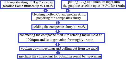
Schematic diagram of fabrication procedure
The whole process steps are summarized in Fig. 2. When the operation is finished and the raw hollow cylinder was prepared through centrifugal casting technique, in the case of industrial application, component must be satisfactorily machined off. The resultant machined component has details dimensions of 200 mm in outer diameter and 1000 mm in length and 12 mm in wall thickness. The essential behavior of FGM depends on microstructure characterization or variations of the intermetallic compound with respect to the location within cast section which are discussed in the next section.
3 Results and Discussion
In this research, to ensure the correctness of results, the laboratories certified by standard organization were applied. The quantitative results are presented in Table 2, and details are discussed in the following sections of this paper.
Results of E, σy, Vθ%, HV, CTE and Wr
| Layers mm | E (MPa) | σy(MPa) | Vθ% | α×(1/0C)10−6 at 115∘C | HV | Wr (g/mm2×10−6) | |||
|---|---|---|---|---|---|---|---|---|---|
| 8-12 Outer | 7534 | 395 | 32.5 | 18.7 | 150 | 11.62 | |||
| 4-8 middle | 8461 | 390 | 33.3 | 19.1 | 151 | 9.51 | |||
| 0-4 Inner | 8076 | 380 | 35.7 | 19.3 | 153 | 9.10 | |||
3.1 FESEM results
FESEM micrograph of Al-Al2Cu FGM tube fabricated through the centrifugal casting method utilizing Al-25 wt.% Cu initially alloy, at different locations across the thickness are demonstrated in Fig. 3(a-f). It must be noted that white phases indicate reinforcement particles of Al2Cu and black region determines α-Al phase. According to Fig. 3(a-f), more Al2Cu particles exist in the region close to the inner layers of the tube compared to layers close to outer layers. It is also found that in the region close to the outer peripheries, particles sizes of Al2Cu become coarser and platelet form, when those are compared to the region close to inner peripheries.
Another interesting point to be noted from Fig. 3(a-f) is that the intermetallic compound particles of Al2Cu are significantly finer and more uniformly distributed and show less particle clustering in the regions close to inner layers compared to locations close to outer layers. The following formation of graded composition in the FGM can persuade the Al2Cu variations across the thickness. In spite of the fact that Al2Cu density is 4.4 g/cm3 and density of molten α-Al is 2.369 g/cm3 (at 650∘C) and centrifugal force can conduct Al2Cu towards outer periphery but the point must be under consideration is that the melt pointing of Al2Cu is 535∘C,whereas the melt pointing of α-Al is 660∘C, since the tube is rapidly solidified from outerto inner wallsdue to cooling effect of mold, the primary α-Al captured before migrating towards the inner layer. Consequently, more Al2Cu particles in the ring’s inner regions are found compared to the ring’s outer regions of thick-walled FG cylindrical shell. There is good correlation between present experimental results and the results reported in reference [15].
Quantitative values of volume fraction of θ-phase Vθ% and volume fraction of α-Al phase Vα% as function of thickness from the inner to outer peripheries of the tubes are calculated by applying computer software (MATLAB code) that works on image analysis. The graded distributions of Vα% and Vθ% are depicted in Fig. 4. The Vθ% in the Al-25wt.% Cu FG tube decreases gradually from 35.7 Vol.% to 32.5 Vol.% which belongs to the region to the inner and outer surfaces of FG cylinder, respectively. In contrast to variations of Vθ%, the Vα% enhances from the inner to outer peripheries of FG cylindrical shell. Variations of weight percentages of Al and Cu as main elements in thick-walled FG cylindrical shell in various zones from the inner to outer walls calculated from EDX analysis which is presented in Fig. 5. It is found that Cu weight percentage monotonically decreases towards ring’s outer region that highest value is 17.26 wt.% and smallest value is 16.06 wt.% located at the inner and outer peripheries, respectively. The experimental results from Fig.5 persuade the experimentally results from Fig. 4 which means by increasing Cu content towards the region close to inner layer of Al-Al2Cu FGM tube, opportunities for formation of Al2Cu particles will be augmented.
In the remaining parts of paper, it becomes ascertained that how the distributions of reinforcing particles contribute the overall mechanical, physical and tribological properties of FG alloy.
3.2 Hardness results
Vickers hardness testing was performed according to ASTM E92 in laboratory certified by iranian national standards organization (RMRC), Tehran, Iran. Fig. 6 illustrates the values of hardness of FGM tube fabricated from Al-25 wt.% Cu alloy at different locations in radial section. It is obvious that the magnitude of hardness increases from the outer to inner walls of FGM cylinder which highest level of hardness with 153 HV was occurred in the inner layer and smallest belongs to the outer layer with 150 HV. The Vickers hardness changes corresponds well with the radial distribution of Al2Cu intermetallic compounds, since the density and hardness of the Al2Cu particle is much larger than those of supersaturated α-Al phase. Consequently, the same trends of Al2Cu variation must be took place to hardness variations.
3.3 Coefflcient of thermal expansion results
Coefficient of thermal expansion examination was carried out at esteemed European Union University (Silesian University of Technology, Gliwice, Poland). Fig. 7 demonstrates the variations of coefficient of thermal expansion at various temperature ranges for locations at 0-4 mm, 4-8 mm and 8-12 mm away from the inner wall of FG tube. The coefficient of thermal expansion gradually changes corresponds to the variation in Al2Cu content. The more
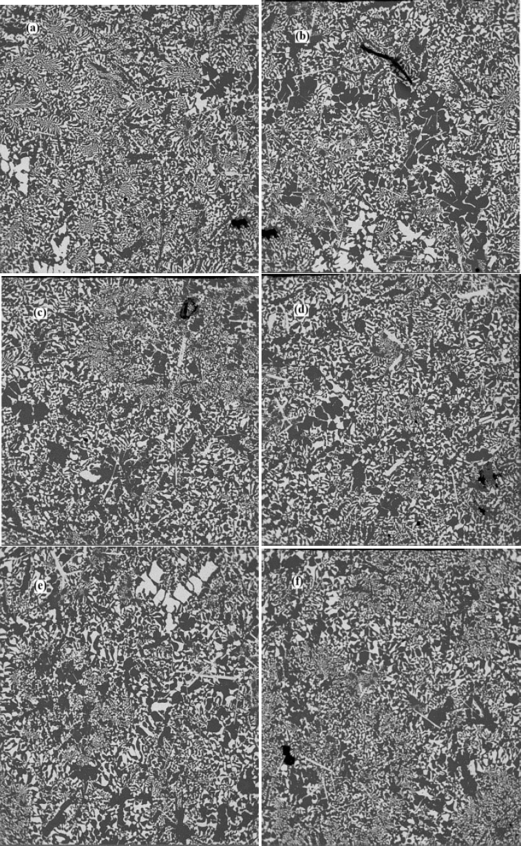
The typical FESEM microstructures of the Al-Al2Cu FGM cylindrical shell at different zones which are (a) 0-2 mm, (b) 2-4 mm, (c) 4-6 mm, (d) 6-8 mm, (e) 8-10 mm, (f) 10-12 mm, from the inner surface along the radial direction.
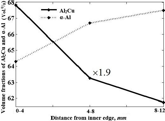
Vθ% and Vα% distribution of thick FGM cylindrical shell along radial direction from inner to outer walls
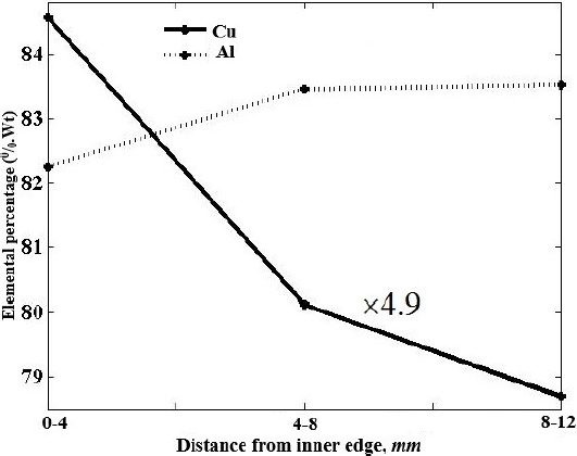
Distribution of Cu and Al along radial direction in the Al-Al2Cu FGM thick cylindrical shell measured by EDX analysis
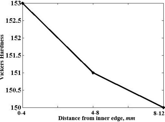
Variation of Vickers hardness values along radial direction for Al-Al2Cu thick FGM cylindrical shell
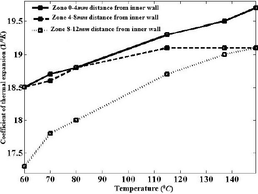
Variation of CTE with temperature for different section of thick FGM cylindrical shell along the radial direction
the content of Al2Cu causes an increase in coefficient of thermal expansion values of specimen. This is due to the fact that the coefficient of thermal expansion of functionally composite is sum of the reinforcement part (Al2Cu precipitation) with coefficient of thermal expansion equals to 8.263×10⁻⁵ K−1 [16] and metal matrix part (supersaturated α-Al) with coefficient of thermal expansion equals to 2.4×10⁻⁵ K−1 [17], consequently increasing Vθ% from the outer to inner walls of FG tube leading to increases in coefficient of thermal expansion of FG metal matrix composite. It is worth to note that during coefficient of thermal expansion evaluation, temperature was from 60∘C to 150∘C at heating rate of 1 ∘K/s.
3.4 Elastic modulus (E) and yield strength (σy) results
The compressive tests were performed to achieve the representative stress-strain curves for three tested sections along the radial direction as the corresponding curves are shown in Fig. 8(a-e).
The elastic modulus was calculated as the initial slope of the straight line that touches curve where in linearity between stress and strain is governed. The yield stress is the point on the stress-strain curve where the linear state (elastic deformation range) is transmitted to the nonlinear state (plastic deformation range). With this explanation, yield stress and elastic modulus as function of distance from the inner edge of FG cylindrical shell are plotted in Fig. 9 and Fig. 10, respectively. Fig. 9 indicates that the yield stress of thick-walled FG cylindrical shell decreased from the outer surface with 395 MPa to the inner surface with 380 MPa by increasing Vθ% from outer wall with 32.5 Vol.0/0 to inner wall with 35.7 Vol.0/0. The compressive yield strength of Al2Cu is about 875 MPa [18] and α-Al phase is about 98 MPa [16] and therefore increasing Al2Cu content causes an increase in σy of FG tube, whereas it causes to falling of σy value. A drop in σy of FG tube from the outer to inner surfaces of thick-walled FG cylindrical shell can be attributed to Chawla phenomenon [19].
The presence of voids due to agglomeration of reinforcement particles at higher than those of optimum of Vθ% cause incompatibility between the matrix, interface and reinforcement and consequently dropping of the resulted FGM yield stress occurred. There is good consistency between present results in Fig. 9 and the results reported in reference [20]. The variations of elastic modulus of thick-walled FG cylindrical shell throughout the thickness have been depicted in Fig. 10. From the experimental results in Fig. 11, it has been revealed that the effects of Al2Cu on elastic modulus (E) is limited up to a certain value of Vθ% which means the value of E can be improved up until reaches the optimum value. The elastic modulus of Al2Cu is 104.5 GPa [21] and elastic modulus of Al is 73 GPa [16] and therefore increasing Vθ% from the intermediate (4-8 mm away from the inner edge) to inner layers (0-4 mm away from the inner edge) of the FG tube normally can cause an increase in the elastic modulus of resulted composite. As one can see from corresponding Fig. 10, negative gradient from the intermediate to inner layers is revealed. This phenomenon known as Chawla can be justified as discussed earlier for the corresponding results of σy in Fig. 9. It is worth to mention that optimum value for elastic modulus of studied FG tube is lower than 32.5 Vθ%. The elastic modulus of the FG is attributed to compatibility between reinforcement content, characteristics of interface bonding between adjacent atomic planes which means increasing the amount of reinforcement particles from designated value, the tendency of particle clustering can be increased and subsequently the conditions for formations of voids and cavities are increased.
Hence, the aggregation of reinforcement at higher optimum values and formation of continuous layer dictate the nature of transition from reinforcement particle enriched to depleted regions. Fig. 10 displays that the highest magnitude of E is 8.46 GPa and lowest value is 7.53 GPa that occurred in 4-8 mm and 8-12 mm away from inner surface of the tube, respectively.
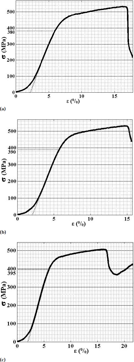
Corresponding stress-strain curves of Al-Al2Cu FGM from compressive test at different section (a) 0-4 mm, (b) 4-8 mm, (c) 8-12 mm, away from inner wall of the cylinder
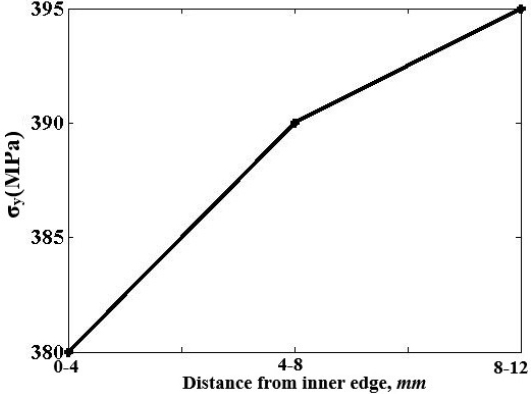
Variation of σy along the radial direction from inner to outer wall of thick FGM cylindrical shell
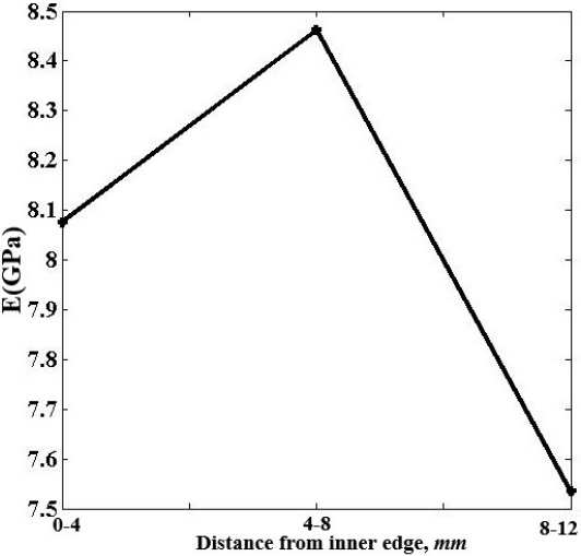
Variation of E along the radial direction from inner to outer walls of thick FGM cylindrical shell
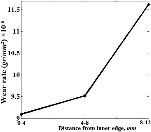
Variation of the Wr along the radial direction from inner to outer walls of thick FGM cylindrical shell under fixed normal load (FN) of 40 KN at linear sliding velocity (SV) of 6.35 :cm/s and sliding distance (Sm) of ~440 m
3.5 Sliding wear test results
The increase of tribological property is one of the major concerning issues of FG materials for mechanical engineering designers. Dry sliding tests have been carried out using computerized pin-on-disc wear testing machine under ambient conditions room temperature and 35% relative humidity. AISI52100 steel pin with hardness of 64 HRC have been used as rotating counter surface. The sample was cut in to slab shape of 2.4 cm×2.4 cm and 2 mm in thickness by wire-cut electrical discharge to obtain region in three section of 0-4 mm, 4-8mm and 8-12mm away from the inner layer. The test performed using fixed normal load (FN) of 40 KN at linear sliding velocity (SV) of 6.35 cm/s and sliding distance (Sm) of ~440 m. In this paper, the estimation of wear rate is based on Eq. 2:
Where, Wr represents wear rate, Δm (g) is the mass loss calculated by weighting sample before and after test and also A (mm2) is specimen’s surface contact area. Fig. 11 demonstrates the results of the evaluated wear rate for Al-25 wt.% Cu centrifugally casted as function of radial distance. According to Fig. 11, the inner layer (the Al2Cu particles rich zone) shows the highest wear resistance with wear rate equals to 9.10×10⁻⁵ g/mm2 compared to other sections along the FG cylindrical shell. It has been proven that there is consistency between reinforcement content, hardness and wear rate. According to experimental results in Fig. 3(a-b), the reinforcement particles in the inner layer are uniformly and finely distributed and also occupy dominant position with 35.7 Vol%. Hence, it leads the layer in distance between 0-4mm away from the inner edge to have the highest hardness (153 HV) and wear resistance (wear rate equals to 9.10×10⁻⁵ g/mm2).
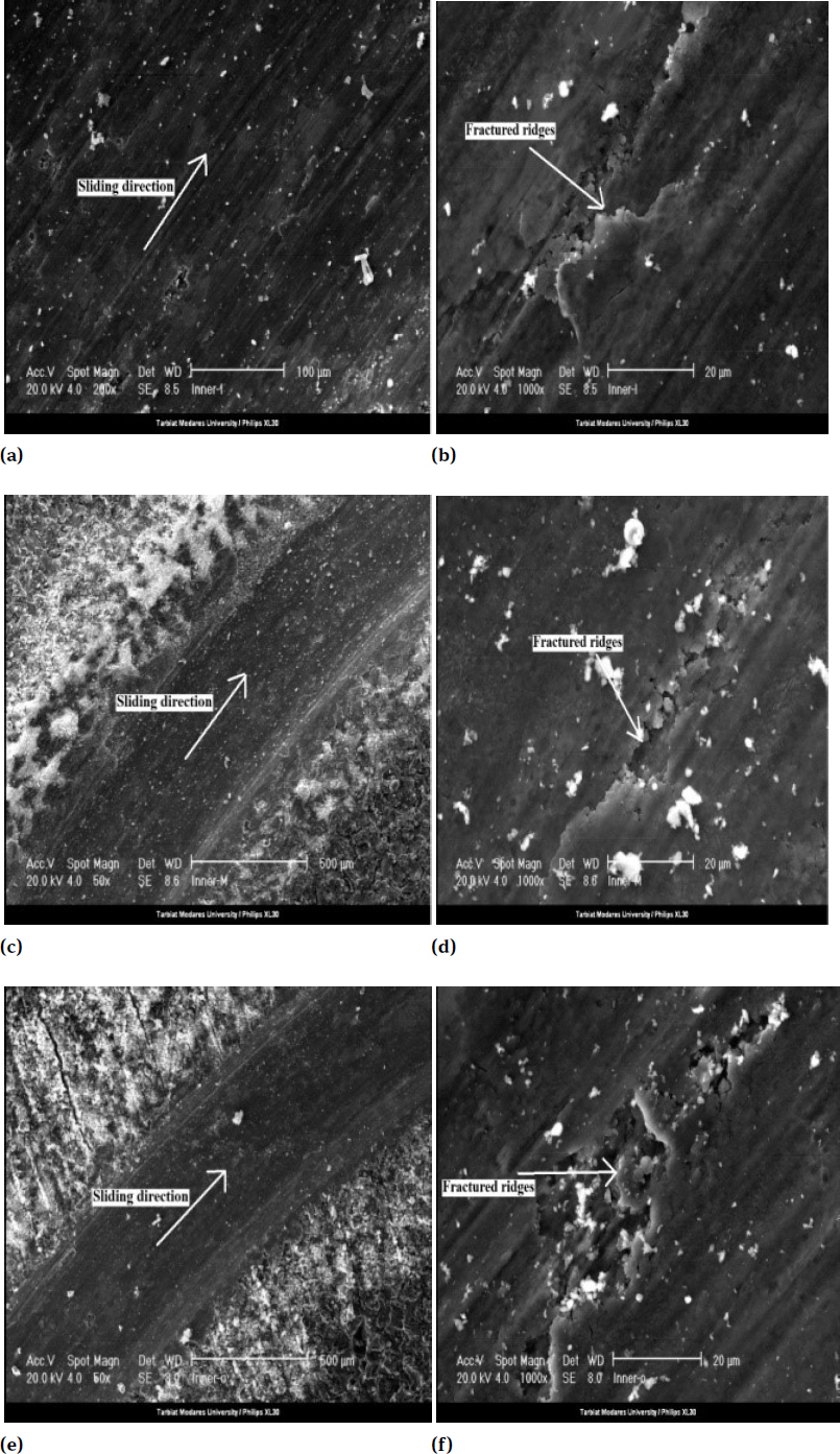
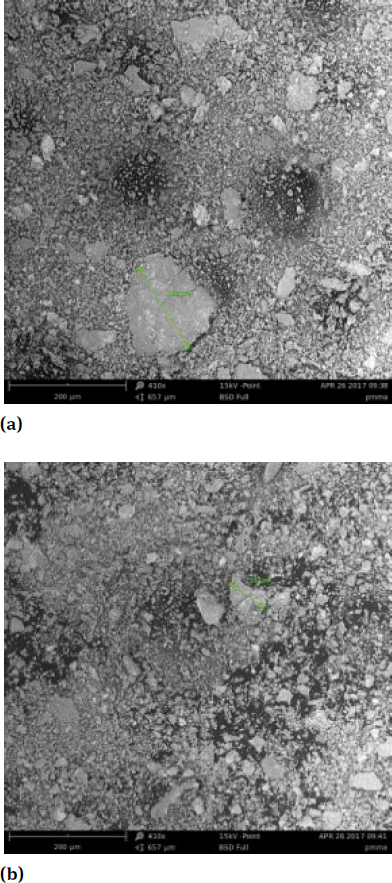
SEM Philips XL30 micrographs of worn surfaces of specimens at the end of wear test, carried out at linear sliding velocity (SV) of 6.35 Cm.s−1 and under fixed normal load (FN) of 40 kN in different test sections (a) and (b) sliding direction and sub-surface cracking for section 0-4 mm away from inner edge of FGM cylinder, respectively, (c) and (d) sliding direction and sub-surface cracking for section 4-8 mm away from inner edge of FGM cylinder, respectively, (e) and (f) sliding direction and sub-surface cracking for section 8-12 mm away from inner edge of FGM cylinder, respectively.
3.6 Wear debris results
The salient features of worn-out surfaces and the morphology of generated collected wear debris were characterized by SEM Philips XL30 and EDX analysis in order to identify the operative wear mechanisms. Fig. 12(a-f) shows the SEM micrograph of the worn-out surfaces of inner, intermediate and outer layers of Al-Al2Cu FGM tube. The micrograph results of worn-out surfaces show that the predominant wear mechanism is abrasive and there is no adhesive mechanism. According to Fig. 12(a-f), the worn- out surface of the inner layer appears considerably smoother than that of other layers which is in good agreement with highest level of hardness and wear resistance in Fig. 6 and Fig. 11. From Fig. 12(a-f), it can be understood that no plastic deformation can be observed and therefore the structure stands mostly in the form of a ductile material which extraordinarily confronts the stresses during dry sliding wear test. Fig. 13 show the nature, size and morphology of the generated wear debris during wear test using SEM micrograph images under fixed normal load (FN) of 40 KN at linear sliding velocity (SV) of 6.35 cm/s. The observation from Fig. 13 indicates that as result of brittle structure, the wear debris do not show any plastic deformation. The approximate sizes of wear debris particles are between 162 μm and 55 μm.
From the reported XRD analysis results (Fig. 14) the investigated wear debris contains Al as main element and a small amount of Cu and Si and also negligible amount of Mg and K which these elements are combined with oxygen.
4 Conclusion
In the present research, the fabrication of thick-walled Al-Al2Cu FG cylindrical shell from Al-25 wt.% Cu alloy was conducted applying horizontal centrifugal casting technique. Compositional graded was created by segregation of particles due to relative melting points differences of the constituent phases and existing of centrifugal force. To understand the FGM behavior, microstructure study by FE-SEM tests was performed to obtain the distributions of intermetallic compounds across the radial direction. To illustrate
Detailed features of collected wear debris generated during the wear test from SEM Philips XL30 micrograph analysis under fixed normal load (FN) 40 kN and at linear sliding velocity (SV) of 6.35 cm/s
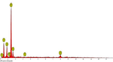
XRD results of the generated wear debris under fixed normal load (FN) 40 kN and at linear sliding velocity (SV) of 6.35 cm/s
the effects of Vθ% on properties at macroscales, various tests with different apparatuses were carried out to measure the variations of graded mechanical, physical, tribological properties and Vickers hardness across the thickness. The important findings of the present investigation are:
It was shown that Vθ% increased from the outer layer to inner layer that statistically report was 32.5 Vol.% to 35.7 Vol.%, respectively.
The experimental results of coefficient of thermal expansion have been demonstrated that the change of coefficient of thermal expansion of thick-walled Al-Al2Cu FGMs cylindrical shell is related to the precipitations of Al2Cu. The addition of Al2Cu from the outer layer (32.5 Vol.%) to the inner layer (35.7 Vol.%) caused an increase in coefficient of thermal expansion of FG tube at the temperature range between 60∘C to 150∘C.
As expected, at the inner layer of FG tube which contains highest Vθ%, the studied advanced composite exhibits the highest hardness with 153 HV and wear resistance with wear rate equals to 9.10×10⁻⁵ g/mm2.
Unlike other distributions of material properties of FG tube, the effects of Al2Cu particles on elastic modulus and yield strength of thick-walled Al-Al2Cu FGM cylindrical shell was limited up to certain value of Vθ%. The optimum Vθ% for studied FGM was lower than 32.5 Vol.%.
Another conclusion from the present research was that with increasing Vθ% from 32.5 Vol.% to 35.7 Vol.%, wear resistance increases 4% while strength reduces less than 2.5%. Hence, the studied advanced FG composite has superior wear resistance and also appropriate strength at the inner surface with density of 3.2 g/cm3.
Nomenclature
- CTE
Coefflcient of thermal expansion
- HRC
Rockwell C Scale Hardness
- E
Module of Elastic
- Vol.
Volume fraction
- EDX
Energy Dispersive X-ray spectroscopy
- Vθ%
Volume fraction of Al2Cu (θ-phase)
- FESEM
Field Emission Scanning Electron Microscopy
- Vα%
Volume Fraction of supersaturated Al (α-phse)
- FGM
Functionally Graded Material
- Wr
Wear Rate
- XRD
X-Ray Diffraction
- HV
Vickers Hardness
- σy
Yield Stress
References
[1] Kieback B, Neubrand A, Riedel H. Mater. Sci. Eng. A. 2003, 362(1), 81-106.10.1016/S0921-5093(03)00578-1Search in Google Scholar
[2] Duque NB, Melgarejo ZH, Suárez OM. Mater. Char. 2005, 55(2, 167-171.10.1016/j.matchar.2005.04.005Search in Google Scholar
[3] Rajan T, Jayakumar E, Pai B. Trans. Indian Inst. Metals. 2012, 65(6), 531-537.10.1007/s12666-012-0191-0Search in Google Scholar
[4] Lin X, Liu C, Xiao H. Compos. Part B: Eng. 2013, 45(1), 8-21.10.1016/j.compositesb.2012.09.001Search in Google Scholar
[5] Zhai Y-B, Liu C-M, Kai W, Zou M-H, Yong X. Trans. Nonfer. Metals Soci. China. 2010, 20(3), 361-370.10.1016/S1003-6326(09)60147-3Search in Google Scholar
[6] Watanabe Y, Hattori Y, Sato H. J. Mater. Proces. Tech. 2015,221, 197-204.10.1016/j.jmatprotec.2015.01.028Search in Google Scholar
[7] Watanabe Y, Oike S. Acta materialia. 2005, 53(6), 1631-1641.10.1016/j.actamat.2004.12.013Search in Google Scholar
[8] Shailesh P, Sundarrajan S, Komaraiah M. Procedia Mater. Sci. 2014, 6, 812-820.10.1016/j.mspro.2014.07.098Search in Google Scholar
[9] Radhika N, Raghu R. Trans. Nonfer. Metals Soci. China. 2016, 26(4), 905-916.10.1016/S1003-6326(16)64185-7Search in Google Scholar
[10] Chen W, Wang Q, Zai C, Ma C, Zhu Y, He W. J. mater. sci. letters. 2001, 20(9), 823-826.10.1023/A:1010954527987Search in Google Scholar
[11] El-Hadad S, Sato H, Miura-Fujiwara E, Watanabe Y. Mater. 2010, 3(9), 4639-4656.10.3390/ma3094639Search in Google Scholar
[12] Kunimine T, Shibuya M, Sato H, Watanabe Y. J. Mater. Proces. Tech. 2015, 217, 294-301.10.1016/j.jmatprotec.2014.11.020Search in Google Scholar
[13] Soflaei H, Vahdat S. Arch. Found. Eng. 2016, 16(2), 99-104.10.1515/afe-2016-0034Search in Google Scholar
[14] Vahdat S. Arch. Found. Eng. 2016, 16(1), 131-137.10.1515/afe-2016-0016Search in Google Scholar
[15] Watanabe Y, Sato H, Ogawa T, Kim I-S.Mater. trans. 2007, 48(11), 2945-2952.10.2320/matertrans.MB200710Search in Google Scholar
[16] Meetsma A, De Boer J, Van Smaalen S. J. Solid State Chem. 1989, 83(2), 370-372.10.1016/0022-4596(89)90188-6Search in Google Scholar
[17] Mehditabar A, Alashti RA, Pashaei M. Int.l J. Eng.-Trans. C: Aspects. 2013, 26(12), 1445.Search in Google Scholar
[18] Davis J. Aluminum and aluminum alloys. ASM International. Handbook Committee. 1993.Search in Google Scholar
[19] Nikhilesh C, Chawla KK. Metal matrix composites. Springer: New York, NY, USA; 2006.10.1002/9783527603978.mst0150Search in Google Scholar
[20] Madhusudan S, Sarcar MMM, Rao NBRM. J. App. Res. Tech. 2016, 14(5), 293-299.10.1016/j.jart.2016.05.009Search in Google Scholar
[21] Westbrook J, Fleischer R. Intermetallic compounds. Vol. 2, Basic mechanical properties and lattice defects of intermetallic compounds: Wiley.Search in Google Scholar
© 2019 Aref Mehditabar et al., published by De Gruyter
This work is licensed under the Creative Commons Attribution 4.0 Public License.
Articles in the same Issue
- Analysis on the impact response of fiber-reinforced composite laminates: an emphasis on the FEM simulation
- Artificial neural network for predicting the flexural bond strength of FRP bars in concrete
- Cyclic behavior of GFRP strengthened infilled RC frames with low and normal strength concrete
- Durability of basalt fiber-reinforced polymer bars in wet-dry cycles alkali-salt corrosion
- Effect of B4C particle size on the mechanical properties of B4C reinforced aluminum matrix layered composite
- Enhanced dielectric properties of BaTiO3 ceramics with cerium doping, manganese doping and Ce-Mn co-doping
- Free and forced vibration analysis of rectangular/circular/annular plates made of carbon fiber-carbon nanotube-polymer hybrid composites
- Influence of nano-SiO2 on the bonding strength and wear resistance properties of polyurethane coating
- Investigation of wear behavior of nanoalumina and marble dust-reinforced dental composites
- Negative effect of clay fillers on the polyvinyl alcohol biodegradation: technical note
- Photocatalytic activity of Cu2O/ZnO nanocomposite for the decomposition of methyl orange under visible light irradiation
- Sub-surface mechanical properties and sub-surface creep behavior of wood-plastic composites reinforced by organoclay
- Surface integrity in wire-EDM tangential turning of in situ hybrid metal matrix composite A359/B4C/Al2O3
- The influence of the WC-Co composite microstructure model on stress field heterogeneity at the microstructure level: FEM based study
- Vibration-damping characterization of the basalt/epoxy composite laminates containing graphene nanopellets
- A review on nanocomposite hydrogels and their biomedical applications
- Optimization and simulation analysis of structure parameters of OPCM ultrasonic longitudinal wave actuating element
- Research Article
- Preparation of POSS-triol/wollastonite composite particles by Liquid phase mechanochemical method and its application in UV curable coatings
- Research on preload relaxation for composite pre-tightened tooth connections
- Dough moulding compound reinforced silicone rubber insulating composites using polymerized styrene butadiene rubber as a compatibilizer
- Hydration And Microstructure Of Astm Type I Cement Paste
- Effects of NiO content on the microstructure and mechanical properties of AgSnO2NiO composites
- Overall buckling behaviour of laminated CFRP tubes with off-axis ply orientation in axial compression
- UV sensing optode for composite materials environment monitoring
- On crushing characteristics of hybrid sandwich aluminum-cardboard panels reinforced with glass fiber composite rods
- Preparation and characterization of Ni-Cu composite nanoparticles for conductive paints
- A research on the preparation of oil-adsorbing hydrophobic porous resins by high internal phase emulsions (HIPEs) template
- Material characteristics of random glass-mat-reinforced thermoplastic under cryogenic thermal cycles
- Differentiation of non-black fillers in rubber composites using linear discriminant analysis of principal components
- Research Article
- Efficiency of TiO2 catalyst supported by modified waste fly ash during photodegradation of RR45 dye
- Synthesis and performance of polyurethane/silicon oxide nano-composite coatings
- Study on preparation of magnesium-rich composite coating and performance enhancement by graft modification of epoxy resin
- Research Article
- Mechanical and wear properties of polyetheretherketone composites filled with basalt fibres
- Mechanical Properties of Al 25 wt.% Cu Functionally Graded Material
- Research Article
- Weight reduction of a carbon fibre composite wheel
- Synthesis, electrical properties, and kinetic thermal analysis of polyaniline/ polyvinyl alcohol - magnetite nanocomposites film
- Seismic Behaviour of TRC-Strengthened RC Columns under Different Constraint Conditions
- Characterization of neat and modified asphalt binders and mixtures in relation to permanent deformation
- Microstructures, interface structure and room temperature tensile properties of magnesium materials reinforced by high content submicron SiCp
- Research Article
- Effect of Cutting Temperature on Bending Properties of Carbon Fibre Reinforced Plastics
- Mechanical and tribological properties of B-C-N coatings sliding against different wood balls
- Thermal conductivity of unidirectional composites consisting of randomly dispersed glass fibers and temperature-dependent polyethylene matrix
- Effects of Waste Eggshells addition on Microstructures, Mechanical and Tribological Properties of Green Metal Matrix Composite
- Investigation of porosity effect on flexural analysis of doubly curved FGM conoids
- Review Article
- Utilization of tailings in cement and concrete: A review
- Research Article
- Equivalent stiffness prediction and global buckling analysis using refined analytical model of composite laminated box beam
- Mechanochemical synthesis of zincite doped with cadmium in various amounts
- Size-dependent vibration analysis of graphene-PMMA lamina based on non-classical continuum theory
- Automated, Quality Assured and High Volume Oriented Production of Fiber Metal Laminates (FML) for the Next Generation of Passenger Aircraft Fuselage Shells
- Research Article
- An investigation of the stitching effect on single lap shear joints in laminated composites
- The low-velocity impact and compression after impact (CAI) behavior of foam core sandwich panels with shape memory alloy hybrid face-sheets
- Effect of granulometric distribution on electromagnetic shielding effectiveness for polymeric composite based on natural graphite
- The enhancement of filament winding in marine launching rubber gasbag
- Research on ELID Grinding Mechanism and Process Parameter Optimization of Aluminum-Based Diamond Composites for Electronic Packaging