Effect of B4C particle size on the mechanical properties of B4C reinforced aluminum matrix layered composite
-
Guangye Xu
 ,
Tingju Li
,
Tingju Li

Abstract
Reinforcement particle size is very important for the performance of metal ceramic composites. This work studied the influence of B4C particle size on the mechanical properties of Al matrix layered composites. These composites were fabricated using a simplified semicontinuous casting and hot-rolling process. To obtain an optimized filling structure of particles, Horsfield filling principle was applied to determine the size and mass fraction of B4C particles. Four sizes of B4C particles were used with various combinations. The results showed that with the increase of the B4C particle size and fine B4C mass fraction, the hardness of the composites decreases whereas the impact strength and ultimate tensile strength increase. The residual stress at interface should be responsible for the variation in properties. Besides, the interparticle distance also contributes to the change in impact strength and ultimate tensile strength.
1 Introduction
Aluminum matrix composite (henceforth referred to as AMC) plays an important role in modern manufacturing industry. By optimized design of the structure and reinforcement phase [1], attractive material properties can be obtained. For example, the boron carbide (B4C)-reinforced aluminum composite is a promising material that possesses the advantages of both Al and B4C, and has gained much attention in the research and application fields. Al alloys are widely used as matrix material owing to their low density, low cost, and good composability [2]. On the other hand, B4C is considered as an ideal reinforcement for AMCs [3] because it possesses not only high hardness but also some other excellent characteristics, such as low density, high temperature stability, and good chemical stability [4].
However, the addition of B4C particles leads to not only the improvement of performance but also some defects, such as brittleness and more fracture formation sites. To balance the positives and negatives, the mass fraction of ceramic reinforcements in AMCs is usually less than 20%. When exceeding this limitation, the AMCs cannot be used due to the significantly increasing brittleness. In this case, a three-layered composite was designed in our work, consisting of B4C-reinforced Al matrix as an inner layer and pure Al as the outer layers. Such a composite combines the advantages of B4C particle-reinforced AMCs and layered material. It is noteworthy that the mass fraction of B4C in the inner layer is 40%, but under the support of the outer Al layer, it still shows better ductility than the conventional B4C-reinforced AMCs. Moreover, its outer layer of pure Al also improves weldability, meeting the industrial requirement [5]. According to previous work [6], this “sandwich” structure composite demonstrates an excellent impact resistance performance as a protective armor material.
It is well known that many techniques are used to fabricate AMCs, for example, powder metallurgy [7], squeeze casting [8], stir casting [9], and continuous casting [10]. Among these, continuous casting is an appropriate way owing to its high efficiency and surface quality, as well as its low cost and energy consumption [11]. Therefore, a simplified semicontinuous casting and following hot-rolling process was used to prepare this layered composite in this paper.
For now, the effect of reinforcement particle size on the mechanical properties of the layered composites has been seldom investigated. It is of great importance to optimize particle size for the final performance of the layered material. In this study, a filling principle was chosen to obtain an optimized particle packing structure of B4C-reinforced Al matrix layered composite (henceforth referred to as BRALC). The effects of the reinforcement particle size and mass fraction on the hardness, impact strength as well as ultimate tensile strength properties of the composite were investigated.
2 Experimental procedures
2.1 Raw materials and Horsfield filling principle
For particle-reinforced AMCs, with increasing reinforcement mass fraction, reinforcement particles distribute in the matrix unhomogeneously, leading to the low performance of the composites. Therefore, in this study, the maximum mass fraction of B4C in the inner layer was set to 40%.
To realize the particles close packing and further eliminate particle agglomeration, the Horsfield filling principle [12], [13], [14], [15] was applied in this work. Both the B4C particles’ size and their respective mass fractions were calculated based on this principle. According to the adding order, the particles are entitled as primary ball, secondary ball, tertiary ball, and so on. Supposing that all the particles are spherical, and the primary balls with the radius of r are filling as the close-packed hexagonal structure, the void fraction of this structure is 25.94%. It can be calculated that the radius of the secondary ball is 0.414r. After adding the secondary ball, the void fraction is decreased to 20.70%. The ball radius and void fraction with addition of the following balls were calculated by the same method, and the results were shown in Table 1. Based on the Horsfield filling principle, B4C particles with four different sizes were used as the reinforcement particles in this study. The average sizes of these four particles were 6.5, 23, 36.5, and 70 μm, respectively, the given particle distributions (from the suppliers) of which were 5.5–7.5 μm, 21.3–24.3 μm, 35–38 μm, and 63–75 μm, respectively. The Al particles adapted in this experiment were 70 μm. Seventy-micrometer B4C and Al particles were chosen as the primary ball, whereas 23- and 6.5-μm B4C particles were chosen as the secondary ball and the tertiary ball, respectively. Reinforcement particles were added up to the tertiary ball, as further addition of finer particles would easily cause B4C agglomeration.
Parameters of the Horsfield filling principle.
| 1st | 2nd | 3rd | 4th | 5th | 6th | |
|---|---|---|---|---|---|---|
| Radius | r | 0.414r | 0.225r | 0.177r | 0.116r | Infinitesimal |
| Void fraction | 0.2594 | 0.2070 | 0.190 | 0.158 | 0.149 | 0.039 |
Figure 1 shows a schematic diagram of the particle filling model. When there is a big difference in particle size between B4C and Al, B4C particles will agglomerate in the gap between Al particles during the powder mixing period as shown in Figure 1A, and the Al particle cannot wrap the reinforcement tightly after hot rolling. After optimizing design by the Horsfield filling principle, the particles are arranged uniformly as shown in Figure 1B, indicating that the agglomeration tendency is alleviated after hot rolling.

The particle filling model: (A) under conventional conditions, (B) according to the Horsfield filling principle.
Table 2 illustrates the details of B4C particle size and mass fraction in the inner layer of the composite. Three types of B4C mixture were used, including one-size particles, as well as two- and three-size particles mixtures. The one-size particle-reinforced BRALCs were named as A1, A2, A3, and A4, respectively, whereas the mixing modes for the two- and three-size conditions were marked as B1, B2, B3, B4, and C1, respectively. Among these, B1 and C1 were designed by Horsfield filling model. For the mechanical tests, all the samples were divided into three groups to make relevant comparison. The first group included samples A1, A2, A3, A4, B1, and C1, to study the variation of mechanical properties caused by the particle size and the application of Horsfield principle. The second group consisted of samples A4, B1, and B2 with various mass fractions of 23 μm B4C particles from 0 (A4) to 5.6 wt.% (B2). The third group contained B3 and B4. The finer size B4C particles in these two-size particle-reinforced BRALCs were changed from 23 (B3) to 36.5 μm (B4).
The B4C particle size and mass fraction of the inner layer.
| Composite designation | The size of B4C particles (μm) | The mass fraction of B4C particles (wt.%) | |
|---|---|---|---|
| Type I (one size) | A1 | 6.5 | 40 |
| A2 | 23 | 40 | |
| A3 | 36.5 | 40 | |
| A4 | 70 | 40 | |
| Type II (two size) | B1 | 70 | 37.2 |
| 23 | 2.8 | ||
| B2 | 70 | 34.4 | |
| 23 | 5.6 | ||
| B3 | 70 | 20 | |
| 23 | 20 | ||
| B4 | 70 | 20 | |
| 36.5 | 20 | ||
| Type III (three size) | C1 | 70 | 26.5 |
| 23 | 2.1 | ||
| 6.5 | 11.4 |
2.2 Experimental installation and process
The BRALCs were produced by a simplified semicontinuous casting method and hot rolling. The outer layer of the composite was pure Al, the inner layer was composed of the mixed particles of Al and B4C. The casting method was designed based on our previous work [10], as shown in Figure 2. The mixed powders were placed in a stainless steel mold, and supported by an Al plate. The molten metal was poured into the mold to form an Al shell, and the cooling rate was 5.12 K/s. The size of the mold was 100 mm in length, and 70 mm in width and height. During the casting process, the stainless steel dividing plate was elevated at a constant rate, and the mixed powders gradually contacted with the solidified Al. After the stainless steel dividing plate was pulled out of the mold completely, the Al melt was poured on the top of the powders to form a layered ingot.

Schematic diagram of the casting method: 1 – crucible; 2 – molten Al; 3 – stainless steel mold; 4 – Al sheet; 5 – stainless steel dividing plate; 6 – Al support; 7 – mixed powders; 8 solidified Al shell.
After the casting process, the layered sample went through hot rolling at 723 K to improve the density of the composites and the bond between layers. The rolling direction is marked in Figure 2. The initial and final thickness of the rolled sample was 70 and 15 mm, respectively, with pass number 22, and a rolling reduction of 3.57% per pass, which corresponds to a reduction of 78.5% in thickness. The cross-section of the after-rolling sample is shown in Figure 3A. For microstructural examination, these samples were cut into small sizes (20 mm×20 mm×15 mm) by line cutting, then polished to investigate the microstructure using scanning electron microscope (SEM).

(A) The cross-section of the layered composite after hot rolling; (B) schematic of the tensile samples.
All the samples were tested for hardness and impact toughness. The hardness test was carried out at room temperature using a digital Brinell test machine. A steel ball with a diameter of 1.5 mm and with a major load of 125 kg was used during the testing. To reduce errors, the hardness was tested at four different positions of the inner layer and the average value was calculated.
Impact toughness test samples were cut along the transverse direction of the composite. The size of the test samples was 10 mm×15 mm in cross-section and 100 mm in length. The test was conducted using a 300/150 impact tester. Each test was conducted at least three times and the average value was calculated. Figure 3A shows the impact direction in this work.
The tensile strength of the composites was measured with the universal testing machine using samples A2, A3, and A4. The tensile specimens were rolled into a thickness of 5 mm and produced under the guidance of GB/T228.1-2010, the schematic of the specimens was indicated in Figure 3B. The fracture surfaces of the tensile specimens were investigated using SEM.
3 Results and discussion
3.1 Microstructures
Figure 4 shows micrographs of the inner layer with different B4C particle sizes and mass fractions. Figure 4A–D presents the microstructural evolution with increasing B4C size in the one-size particle-reinforced BRALCs. It is clear from Figure 4A that 6.5 μm B4C particles tend to agglomerate at the grain boundary, particles are mainly distributed in the intergranular gaps due to the large difference between B4C and Al particles size. The void in the agglomeration areas induces considerable reduction of the mechanical properties. Figure 4B–D indicates that with the increasing B4C size, the particles distribute more uniformly in the matrix. It is noted that B4C particles were easily fractured in A4. As the same particle size of matrix and reinforcement (70 μm), some B4C particles would intercontact with each other during the particle mixing process. These particles were easily fractured during the hot-rolling process. After application of the Horsfield filling principle, B1 and C1 showed homogeneous particle distribution. However, as more 6.5-μm B4C particles were added, part of these fine particles started to agglomerate slightly. To avoid further agglomeration, the Horsfield filling principle was applied to the tertiary ball in the present study.

The dispersion of B4C particles in the inner layer of all BRALCs samples: (A) A1, (B) A2, (C) A3, (D) A4, (E) B1, (F) B2, (G) B3, (H) B4, and (I) C1.
Compared with A4, B1 and B2 show fewer 70-μm B4C particle fractures with the addition of more 23 μm B4C particles. The addition of finer B4C particles effectively reduced particle fracture. This tendency can also be observed in other multiple-size particle-reinforced BRALCs.
B3 and B4 changed the finer B4C particle size from 23 to 36.5 μm. Due to the large mass fraction of 23 μm B4C particles, particles agglomerated at some areas. More 70-μm B4C particles fractured in B4 than that in B3. Besides, it can be found that the interval between particles increases with increasing finer particle size.
From Figure 4I, it can be seen that the “secondary ball” distributed in the surroundings of the “primary ball”, with the “tertiary ball” distributed in the gap between the “primary ball” and “secondary ball”. This microstructural result basically followed the Horsfield filling principle that “the smaller balls locate in the space between bigger balls”, and it is close to the Horsfield particle packing model as indicated in Figure 1B. Besides, Al particles also act as primary balls in this experiment. It can be seen from Figure 4I that the deformation of Al particles during the hot-rolling process has no significant influence on B4C particle distribution.
In this work, the Horsfield filling principle still works under the condition of nonspherical particles. The particle arrangement based on Horsfield filling principle could reduce the agglomeration of 6.5 μm B4C, and further improve mechanical properties. It is considered that the B4C shape has no obvious influence on the experimental results.
The interface between reinforcement and matrix is of great importance to the mechanical properties of the composites. A poor bond would badly deteriorate the mechanical properties of the composites. Figure 5 represents the typical SEM image of the inner layer microstructure of A4, in which no obvious reaction product could be found near the interface between Al and B4C. To verify the inexistence of interfacial reaction, line scanning analysis was carried out across the interface as marked in Figure 5. The result indicates that no reaction products were found at the interface, suggesting that there was little reaction between B4C and Al in this study. According to Pyzik et al. [16], B4C and Al will react with each other at higher than 873 K. At 873–973 K AlB2 mainly forms. At 973–1173 K, the reaction products are AlB2 and Al4BC. At 1173–1253 K, primarily Al4BC forms. The reaction products are AlB24C4 and a small amount of Al4C3 at a temperature range from 1273 to 1323 K (<5 h). All these hard and brittle reaction products do harm to the mechanical properties of the composite. Therefore, the hot-rolling temperature was set at 723 K in this work to avoid these reaction products. Because the fabrication conditions of the other samples were the same with A4, there should not be reaction products at the interface, which will not be shown in detail here.

Line scanning of B4C-Al interface in sample A4.
3.2 Hardness test
Figure 6 shows the hardness test results. The hardness test of the first group (A1, A2, A3, A4, B1, and C1) was carried out to reveal the difference between the one-size and multiple-size particle-reinforced BRALCs. Compared with pure Al (16 HB), the hardness of A1 (22 HB), A2 (40.77 HB), A3 (37.39 HB), A4 (34.15 HB), B1 (39.05 HB), and C1 (39.46 HB) increased by 37.5%, 154.8%, 133.7%, 113.4%, 144.1%, and 146.6%, respectively. This fact can be analyzed through the rule of mixtures [17]. The addition of B4C enhances the hardness of the composites, this relationship can be described by the following equation:

The Brinell hardness of all the samples.
where H is the hardness value, f is the mass fracture. The subscripts c, m, r refer to composite, matrix, and reinforcement, respectively. The hardness value of B4C is far greater than that of Al matrix; therefore, the hardness of the composite significantly exceeds that of the matrix. The equation also indicates that with the increase of B4C mass fracture, the hardness of the composite increases.
It is considered that the hardness of composites should be the same when adding identical B4C mass fraction based on Equation 1. However, according to the results, the hardness increases with the decrease of the B4C size under the same condition of B4C content, indicating that the size and ratio play an important role in the mechanical properties. There is also an exception of A1, the agglomeration of B4C particles at the grain boundary causes a decrease of the matrix-reinforcement bond, as well as its mechanical properties.
The Horsfield filling principle effectively reduces B4C particle agglomeration in the inner layer. Therefore, the hardness of B1 and C1, which were optimally designed and close packing, were higher than those of the A1 and A4. Based on the Horsfield filling principle, C1 has a better structure than B1 due to the addition of 6.5 μm B4C particles, its hardness is higher than B1 as a result.
The second group represents the variation of hardness caused by different 23 μm B4C mass fraction and includes samples A4, B1, and B2. The mass fraction of 23 μm B4C in those samples was 0%, 2.8%, and 5.6%, respectively. The results indicate that by increasing the 23 μm B4C mass fraction, the hardness increases. B2 possesses higher hardness (39.5 HB) compared with B1 (39.05 HB), and A4 (34.15 HB). The results in the third group suggest that with fine size B4C in two-size particle-reinforced BRALCs changing from 23 to 36.5 μm (B3 and B4), the hardness decreases from 40.33 HB to 39.62 HB.
It can be concluded that with decreasing B4C particle size in one-size B4C-reinforced AMCs as well as with increasing fine B4C mass fraction in multiple-size B4C-reinforced AMCs, the hardness of the composites increases.
Three main mechanisms have been speculated to increase strength in particle-reinforced metal composites, including [18] (1) Orowan strengthening from dislocation bowing by reinforcement particles; (2) Hall–Petch strengthening from grain refinement; and (3) residual stress caused by the difference of coefficient of thermal expansion (CTE) as well as elastic modulus between matrix and reinforcement, which will hinder the motivation of the dislocation.
The Orowan mechanism is caused by the resistance of closely spaced hard particles to the passing of dislocations in nanostructured materials. It is widely acknowledged that Orowan strengthening is not significant in the microsized particle-reinforced metal matrix composites because the reinforcement particles are coarse and the interparticle spacing is large [19]. On the other hand, in this experiment, the fabrication condition and Al powders of the inner layer in all samples were the same, thus the difference in the grain size could be ignored. The grain refinement did not contribute as a main reason for the increasing hardness.
Therefore, the difference of the CTE as well as elastic modulus between matrix and reinforcement leads to increasing composite strength. The difference of CTE and elastic modulus generates geometrical dislocations and thermal residual stresses during the hot-rolling process [20], which will hinder the motivation of the dislocation, and enhance the hardness of the composites. Besides, according to Williams’ work [21], due to plastic incompatibility between the reinforcement and matrix, dislocation tangles form around the particles. The cell structure dislocation with a cell size inversely proportional to the reinforcement particle size could contribute to the increase in strength, which should be the main reason for the increase of hardness with reinforcement particle size decreasing.
It can be seen from the test results that only slight differences occur among samples B1, B2, B3, and B4, which seems statistically insignificant. However, these results reflect the role of the hardness test, and need to be further discussed in this study.
It can be concluded from the role of the hardness test that reinforcement particle type, mass fraction, and distribution condition are major factors that determine the hardness value of particle-reinforced AMC, differences of which lead to a significant variation in hardness, whereas residual stress in the interface between matrix and reinforcement, which is formed during the hot-rolling process in this experiment, plays a secondary factor and slightly influences the hardness value [22], [23]. These discussions are in accordance with the results indicated in Figure 6. In this experiment, as the mass fraction of B4C was 40%, particle distribution condition was the major factor that determined hardness value. It can be seen from Figure 2A–D, with increasing B4C particle size (from 6.5 to 70 μm), the B4C particle density per unit area decreased significantly, leading to an obvious variation in hardness (from 22.32 to 40.77 HB). For two-size B4C-reinforced AMCs (samples B1, B2, B3, and B4), the variation of reinforcement size and mass fraction slightly influences B4C particle distribution condition, no obvious variation in the B4C distribution condition could be observed. Therefore, residual stress is the main reason for the fluctuation in hardness among these samples. Because it is a secondary factor that determines hardness variation, only slight changes occur.
3.3 Impact toughness
Figure 7 shows the results of impact toughness tests. For the first group samples, with increasing particle size, the impact strength increases. A4 shows the highest impact strength (163.2 J), whereas A1 displays the lowest (32.8 J). The impact strength of B1 (146 J) is higher than that of C1 (51.5 J).
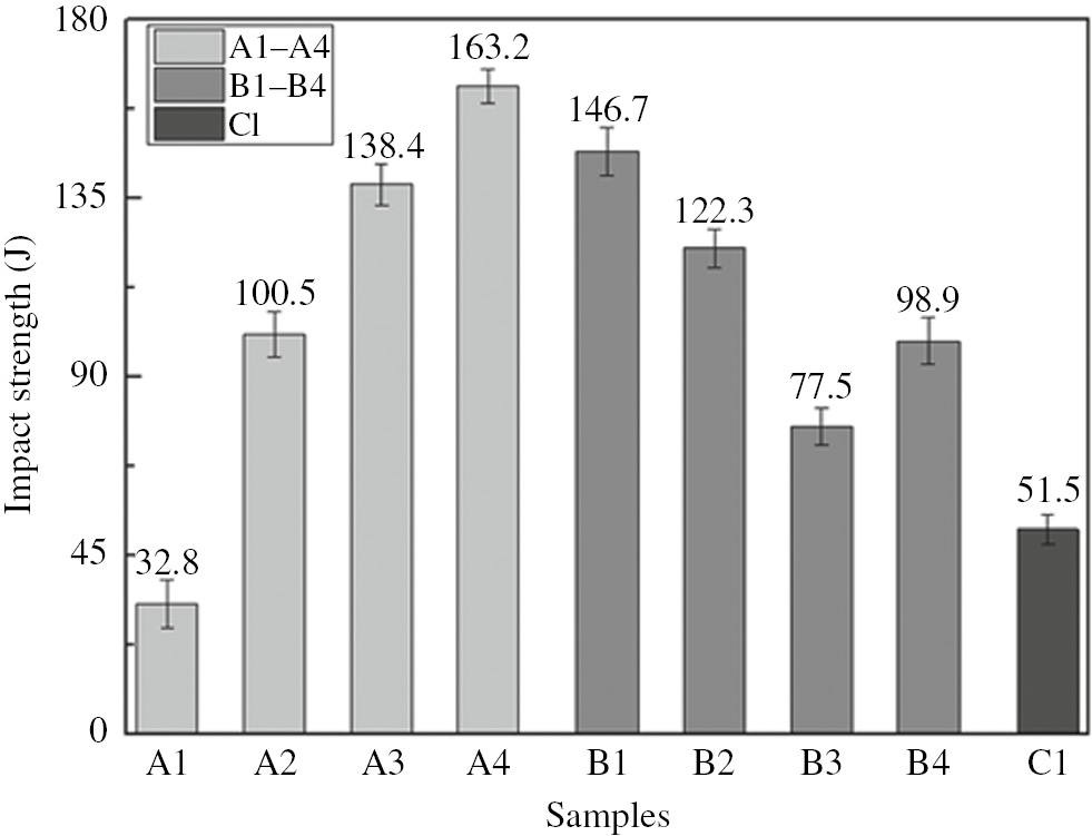
The impact strength of all the samples.
The result of the second group shows that with increasing finer size B4C mass fraction, the impact strength decreases. A4 acquires the highest impact strength (163.2 J) as compared to B1 (146 J) and B2 (122 J). The comparison between B3 and B4 shows that the increase of finer B4C particle size leads to increasing impact strength. B4 acquires higher impact strength (98 J) than B3 (77 J).
It can be concluded that increasing the mass fraction of coarse B4C particles results in an increase of impact strength. A previous study indicates that reinforcement particles work as potent sites for the nucleation of porosities [24]. It has been found that for particle-reinforced metal matrix composites, the following relationship is applicable [17]:
where λ is the distance apart from the reinforcement, f is the fractional volume of the reinforcement, and r is the radius of the particles (assumed spherical). Therefore, the smaller the size of B4C, the shorter the distance between particles. This facilitates linkage between neighboring voids and microscopic cracks [25]. Besides, with the increase of B4C size, there is more Al matrix in the inter particle regions. It may enhance the impact toughness because the matrix material has a significant effect on the impact behavior of composites [26].
The residual stress also contributes to the difference of impact strength. More residual stress will form in the interface of finer particle-reinforced BRALCs during the hot-rolling process, which further makes the fracture growth easier.
The low impact strength of A1 is caused by the particle agglomeration, which decreases the matrix-reinforcement bond. Moreover, the agglomerated particles separate easily under impact loading, which makes agglomeration areas preferential sites for crack nucleation and propagation [25]. When these two failure reasons combine, the impact strength of A1 decreases considerably.
3.4 Tensile test
The tensile test was conducted among samples A2, A3, and A4 to investigate the interfacial bond between B4C and Al, as well as the reasons for the fracture. Figure 8 shows the results of ultimate tensile strength, which indicates that the ultimate tensile strength increases with the increase of B4C particle size. For particle-reinforced AMC produced by powder metallurgy technique, the relation between ultimate tensile strength value variation tendency and relative particle size of reinforcement and matrix can be described by the following equation [27]:

Ultimate tensile strength of samples.
where A is a constant, x means the size ratio of matrix and reinforcement (i.e. Al particle and B4C particle). According to the theoretical prediction, the ultimate tensile strength increases with the increase of reinforcement particle size. The more interfacial residual stress and shorter reinforcement particle distance of fine particle-reinforced BRALCs lead to lower ultimate tensile strength.
Figure 9 shows the fracture surfaces of these samples, the fracture surfaces of A3 and A4 involve dimples. For a composite undergoing elastic loading [21], a significant fraction of the stress is initially borne by the reinforcements. When the composite undergoes microplastic yielding, microplasticity in the composites takes place locally with high stress concentrations. The dimples should be the result of the void nucleation and subsequent coalescence by strong shear deformation. The main reason for the fracture in A2 was the formation and growth of fracture around the B4C particles. Whereas the reason in A4 was the nucleation and coalescence of the void in the matrix because no obvious fracture formation was observed around the B4C particles. The reason for the fractures in A3 included fracture growth and void coalescence. Larger areas of fracture growth were observed in A2 than those in A3 and A4. For A2, the agglomerated particles were the sites for damage accumulation and the local particle-rich regions were the most favorable nucleation sites for the cracks, the damage generated in the particle-rich regions were due to the higher stress concentration at small strains [28], [29], [30]. From the reasons for the fracture, it can be considered that more residual stress exists in the interface between matrix and fine reinforcement, which can be attributed to the increasing hardness value.

Fracture surfaces of the tensile samples: (A) A2, (B) A3, and (C) A4.
Figure 9 also indicates that there are a few instances of decohesion between the reinforcement and the matrix, which proves good interfacial bond. Hot rolling is a good way to decrease the number of pores in the composites and acquire a good bond between matrix and reinforcement.
4 Conclusions
In this study, the influence of B4C particle size and mass fraction on the mechanical properties of the layered Al-B4C composite was investigated. The following results were obtained:
Horsfield filling principle can reduce B4C agglomeration areas in the inner layer.
By increasing the B4C particle size and decreasing fine B4C mass fraction, the hardness decreases whereas the ultimate tensile strength and impact strength increase.
More residual stress exists near the interface between the matrix and fine reinforcement, which contributes to the increasing hardness and decreasing ultimate tensile strength as well as impact strength. Furthermore, the shorter distance between B4C particles further decreases ultimate tensile strength as well as impact strength.
Funding source: National Natural Science Foundation of China
Award Identifier / Grant number: 51501027
Award Identifier / Grant number: 51471042
Funding statement: This work was supported by the “National Natural Science Foundation of China” (nos. 51501027 and 51471042), the Fundamental Research Funds for the Central Universities of China DUT17RC(4)01, and the Open Research Fund from State Key Laboratory of Metal Material for Marine Equipment and Application (no. SKLMEA-K201701) and the State Key Laboratory of Rolling and Automation, Northeastern University.
References
[1] Taha MA. Mater Manuf Process 2001, 16, 619–641.10.1081/AMP-100108625Search in Google Scholar
[2] Torralba JM, Da Costa CE, Velasco F. J Mater Process Technol 2003, 133, 203–206.10.1016/S0924-0136(02)00234-0Search in Google Scholar
[3] Kennedy AR. J Mater Sci 2002, 37, 317–323.10.1023/A:1013600328599Search in Google Scholar
[4] Thevenot F. J Eur Ceram Soc 1990, 6, 205–225.10.1016/0955-2219(90)90048-KSearch in Google Scholar
[5] Zhang S, Yu YS, Tu JH, Li TJ. Adv Mater Res 2013, 602–604, 80–84.10.4028/www.scientific.net/AMR.602-604.80Search in Google Scholar
[6] Wang D, Xue X, Liu R, Zhang S. Mater Rev 2007, 21, 388–390.Search in Google Scholar
[7] Jiang L, Li Z, Fan G, Cao L, Zhang D. Carbon 2012, 50, 1993–1998.10.1016/j.carbon.2011.12.057Search in Google Scholar
[8] Pan J, Ning X, Hu K, Ye H. Acta Metall Sin 1993, 6, 465–471.Search in Google Scholar
[9] Poddar P, Srivastava VC, De PK, Sahoo KL. Mater Sci Eng A 2007, s 460–461, 357–364.10.1016/j.msea.2007.01.052Search in Google Scholar
[10] Yu Y, Jie J, Zhang S. Powder Metall Met Ceram 2015, 54, 390–396.10.1007/s11106-015-9727-2Search in Google Scholar
[11] Ji X, Zhang H, Luo S, Jiang F, Fu D. Mater Sci Eng A 2016, 649, 128–134.10.1016/j.msea.2015.09.114Search in Google Scholar
[12] Johnsen V, Andersen PJ. Mater Sci Concretes 1991, 2, 111–146.Search in Google Scholar
[13] Broday DM, Agnon Y. J Aerosol Sci 2007, 38, 701–718.10.1016/j.jaerosci.2007.06.001Search in Google Scholar
[14] Zhang T, Yu Q, Wei J, Zhang P. Cem Concr Compos 2012, 34, 692–699.10.1016/j.cemconcomp.2012.02.004Search in Google Scholar
[15] Fayed ME, Otten L, Eds., Handbook of Powder Science & Technology, 2nd ed., Springer USA: New York, 1997.10.1007/978-1-4615-6373-0Search in Google Scholar
[16] Pyzik AJ, Beaman DR. Cheminform 1996, 27, 305–312.10.1080/714041312Search in Google Scholar
[17] Rahimian M, Ehsani N, Parvin N, Baharvandi HR. Mater Des 2009, 30, 3333–3337.10.1016/j.matdes.2008.11.027Search in Google Scholar
[18] Ferguson JB, Sheykh-Jaberi F, Kim CS, Rohatgi PK, Cho K. Mater Sci Eng A 2012, 558, 193–204.10.1016/j.msea.2012.07.111Search in Google Scholar
[19] Zhang Z, Chen DL. Scr Mater 2006, 54, 1321–1326.10.1016/j.scriptamat.2005.12.017Search in Google Scholar
[20] Habibnejad-Korayem M, Mahmudi R, Poole WJ. Mater Sci Eng A 2009, 519, 198–203.10.1016/j.msea.2009.05.001Search in Google Scholar
[21] Williams JJ, Piotrowski G, Saha R, Chawla N. Metall Mater Trans A 2002, 33, 3861–3869.10.1007/s11661-002-0258-3Search in Google Scholar
[22] Shaw MC, Desalvo GJ. Metallography Microstruct Anal 2012, 1, 310–317.10.1007/s13632-012-0047-3Search in Google Scholar
[23] Shen YL, Chawla N. Mater Sci Eng A 2015, 297, 44–47.10.1016/S0921-5093(00)01256-9Search in Google Scholar
[24] Sajjadi SA, Ezatpour HR, Parizi MT. Mater Des 2012, 34, 106–111.10.1016/j.matdes.2011.07.037Search in Google Scholar
[25] Ozden S, Ekici R, Nair F. Compos Part A Appl Sci Manuf 2007, 38, 484–494.10.1016/j.compositesa.2006.02.026Search in Google Scholar
[26] Kamat SV, Hirth JP, Mehrabian R. Acta Metall 1989, 37, 2395–2402.10.1016/0001-6160(89)90037-0Search in Google Scholar
[27] Prasad VVB, Bhat BVR, Mahajan YR, Ramakrishnan P. Mater Sci Eng A 2002, 337, 179–186.10.1016/S0921-5093(02)00024-2Search in Google Scholar
[28] Hong SJ, Kim HM, Huh D, Suryanarayana C, Chun BS. Mater Sci Eng A 2003, 347, 198–204.10.1016/S0921-5093(02)00593-2Search in Google Scholar
[29] Clyne TW, Withers PJ. An Introduction to Metal Matrix Composites. Cambridge University Press: New York, NY, USA, 1993.10.1017/CBO9780511623080Search in Google Scholar
[30] Conlon KT, Wilkinson DS. Mater Sci Eng A 2001, 317, 108–114.10.1016/S0921-5093(01)01168-6Search in Google Scholar
©2019 Walter de Gruyter GmbH, Berlin/Boston
This work is licensed under the Creative Commons Attribution 4.0 Public License.
Articles in the same Issue
- Analysis on the impact response of fiber-reinforced composite laminates: an emphasis on the FEM simulation
- Artificial neural network for predicting the flexural bond strength of FRP bars in concrete
- Cyclic behavior of GFRP strengthened infilled RC frames with low and normal strength concrete
- Durability of basalt fiber-reinforced polymer bars in wet-dry cycles alkali-salt corrosion
- Effect of B4C particle size on the mechanical properties of B4C reinforced aluminum matrix layered composite
- Enhanced dielectric properties of BaTiO3 ceramics with cerium doping, manganese doping and Ce-Mn co-doping
- Free and forced vibration analysis of rectangular/circular/annular plates made of carbon fiber-carbon nanotube-polymer hybrid composites
- Influence of nano-SiO2 on the bonding strength and wear resistance properties of polyurethane coating
- Investigation of wear behavior of nanoalumina and marble dust-reinforced dental composites
- Negative effect of clay fillers on the polyvinyl alcohol biodegradation: technical note
- Photocatalytic activity of Cu2O/ZnO nanocomposite for the decomposition of methyl orange under visible light irradiation
- Sub-surface mechanical properties and sub-surface creep behavior of wood-plastic composites reinforced by organoclay
- Surface integrity in wire-EDM tangential turning of in situ hybrid metal matrix composite A359/B4C/Al2O3
- The influence of the WC-Co composite microstructure model on stress field heterogeneity at the microstructure level: FEM based study
- Vibration-damping characterization of the basalt/epoxy composite laminates containing graphene nanopellets
- A review on nanocomposite hydrogels and their biomedical applications
- Optimization and simulation analysis of structure parameters of OPCM ultrasonic longitudinal wave actuating element
- Research Article
- Preparation of POSS-triol/wollastonite composite particles by Liquid phase mechanochemical method and its application in UV curable coatings
- Research on preload relaxation for composite pre-tightened tooth connections
- Dough moulding compound reinforced silicone rubber insulating composites using polymerized styrene butadiene rubber as a compatibilizer
- Hydration And Microstructure Of Astm Type I Cement Paste
- Effects of NiO content on the microstructure and mechanical properties of AgSnO2NiO composites
- Overall buckling behaviour of laminated CFRP tubes with off-axis ply orientation in axial compression
- UV sensing optode for composite materials environment monitoring
- On crushing characteristics of hybrid sandwich aluminum-cardboard panels reinforced with glass fiber composite rods
- Preparation and characterization of Ni-Cu composite nanoparticles for conductive paints
- A research on the preparation of oil-adsorbing hydrophobic porous resins by high internal phase emulsions (HIPEs) template
- Material characteristics of random glass-mat-reinforced thermoplastic under cryogenic thermal cycles
- Differentiation of non-black fillers in rubber composites using linear discriminant analysis of principal components
- Research Article
- Efficiency of TiO2 catalyst supported by modified waste fly ash during photodegradation of RR45 dye
- Synthesis and performance of polyurethane/silicon oxide nano-composite coatings
- Study on preparation of magnesium-rich composite coating and performance enhancement by graft modification of epoxy resin
- Research Article
- Mechanical and wear properties of polyetheretherketone composites filled with basalt fibres
- Mechanical Properties of Al 25 wt.% Cu Functionally Graded Material
- Research Article
- Weight reduction of a carbon fibre composite wheel
- Synthesis, electrical properties, and kinetic thermal analysis of polyaniline/ polyvinyl alcohol - magnetite nanocomposites film
- Seismic Behaviour of TRC-Strengthened RC Columns under Different Constraint Conditions
- Characterization of neat and modified asphalt binders and mixtures in relation to permanent deformation
- Microstructures, interface structure and room temperature tensile properties of magnesium materials reinforced by high content submicron SiCp
- Research Article
- Effect of Cutting Temperature on Bending Properties of Carbon Fibre Reinforced Plastics
- Mechanical and tribological properties of B-C-N coatings sliding against different wood balls
- Thermal conductivity of unidirectional composites consisting of randomly dispersed glass fibers and temperature-dependent polyethylene matrix
- Effects of Waste Eggshells addition on Microstructures, Mechanical and Tribological Properties of Green Metal Matrix Composite
- Investigation of porosity effect on flexural analysis of doubly curved FGM conoids
- Review Article
- Utilization of tailings in cement and concrete: A review
- Research Article
- Equivalent stiffness prediction and global buckling analysis using refined analytical model of composite laminated box beam
- Mechanochemical synthesis of zincite doped with cadmium in various amounts
- Size-dependent vibration analysis of graphene-PMMA lamina based on non-classical continuum theory
- Automated, Quality Assured and High Volume Oriented Production of Fiber Metal Laminates (FML) for the Next Generation of Passenger Aircraft Fuselage Shells
- Research Article
- An investigation of the stitching effect on single lap shear joints in laminated composites
- The low-velocity impact and compression after impact (CAI) behavior of foam core sandwich panels with shape memory alloy hybrid face-sheets
- Effect of granulometric distribution on electromagnetic shielding effectiveness for polymeric composite based on natural graphite
- The enhancement of filament winding in marine launching rubber gasbag
- Research on ELID Grinding Mechanism and Process Parameter Optimization of Aluminum-Based Diamond Composites for Electronic Packaging