On crushing characteristics of hybrid sandwich aluminum-cardboard panels reinforced with glass fiber composite rods
-
Gabriel Y. Fortin
 ,
Elsayed A. Elbadry
,
Elsayed A. Elbadry

1 Introduction
Ensuring that the automobiles of the future are safer in terms of crashworthiness with minimal carbon footprint are ongoing challenges that we face. According to the latest report from the International Organization of Motor Vehicle Manufacturers (OICA), approximately 70 million passenger cars were produced in 2017 [1]. Clearly, automotive structures must make greater use of materials that are both light and strong in order to minimize environmental impacts and to ensure structural integrity during a crash event. Composite materials, particularly fiber-reinforced plastics, are an excellent candidate for meeting these requirements. They are lightweight, stiff, and strong materials that provide weight savings and improved fuel efficiency in service. In addition, their anisotropic properties allow for flexibility in design and can be tailored as required for optimal load paths [2]. The crashworthiness properties of composite materials must therefore be well understood.
The use of composite structures in crashworthiness applications, particularly in the form of tubes and rods has been fundamentally studied by Thornton et al. [3, 4], Hull et al. [5, 6, 7, 8], Fairfull et al. [9, 10] and Hamada et al. [11, 12]. A lot of recent work on energy absorption and crashworthiness of composite materials in axial compression has also been performed by Yang et al. [13], Ma et al. [14], Xu et al. [15], Kathiresan et al. [16], Sun et al. [17], Wang et al. [18], Atthapreyangkul et al. [19], Eshkoor et al. [20], and Alkbir et al. [21]. The authors [3, 4, 5, 6, 7, 8, 9, 10, 11, 12] have shown that even if composite materials are brittle in nature compared to metals, well designed composite tubes can absorb significant amounts of energy during crushing through multiple micro-fracture processes and can exhibit a stable crushing mechanism known as progressive crushing. They reported that composite tubes that are designed with a trigger at one end such as a chamfer angle will exhibit progressive crushing behavior. During this behavior the load increases to a maximum value, and then proceeds to a constant value where progressive crushing takes place throughout the remaining structure. During progressive crushing of composite tubes, radial fiber splaying occurs outwards from the chamfer end until the tube is fully compacted. Splaying of fibers is a clear sign that an optimal amount of energy is being absorbed during compression.
Alia et al. [22, 23, 24] have investigated the crushing energy absorption characteristics of small composite tube and metal tube-reinforced polymer foam panels for crashworthiness applications. In addition to being lightweight, they found that the surrounding foam provided additional benefits to the crushing performance of the tubes.
Fortin et al. [25] have studied the crushing behavior and specific energy absorption of small braided glass fiber composite rods inserted in corrugated cardboard panels for automotive crashworthiness. Static compression testing was performed, and they found that the specific energy absorption of rods embedded in cardboard is superior to rods without cardboard, and that relatively thin single-layer cardboard panels reinforced with shorter rods performed better than thicker panels with longer rods due to reduced cardboard shifting and inclination of rods. As cardboard materials are inexpensive, easy to access, and made from recycled paper, they are attractive for affordable and rapid processing of parts with benefits to the environment.
Recent work has also been done by Paruka et al. [26, 27], Harms et al. [28], Shin et al. [29], Reuter et al. [30], Kim et al. [31], Liu et al. [32], Wu et al. [33], and Zhu et al. [34] on crashworthiness of hybrid structures consisting of metals, primarily aluminum, and fiber-reinforced polymer composites. Their work focuses largely on hybrid tubular structures and sandwich panels with the aim to obtain benefits of performance, weight reduction, and low-cost from combining lightweight metals with composites in crash applications.
No previous research investigated the effect of stacked aluminum layers on the crushing behavior of hybrid polymer composites, therefore, this paper focuses on crashworthiness properties of different configurations of stacked aluminum-cardboard panels reinforced with braided glass fiber-reinforced epoxy rods manufactured using a tubular braiding machine through quasi-static compression tests.
2 Experimental Procedures
2.1 Braided rods manufacturing and panel preparation
The rods in this study consist of unidirectional glass fibers at the core covered by braided glass fibers, as manufactured in a previous study by Fortin et al. [25]. Fibers for the axial and braiding portions of the rod (type RS 57QM-521) have been provided by Nitto Boseki Co., Ltd. The braided preform for the rods was manufactured in an industrial tubular braiding machine. The braiding process is shown in Figure 1(a). The axial fiber bobbins were placed behind the braiding machine. A small stopper with a hole large enough to allow 18 fiber bundles to be guided was attached behind the braiding machine. The axial fibers were then altogether covered by the 8 braiding fiber bundles. To achieve a braiding angle of 45∘ for a diameter of 3.5 mm, the machine take-up speed (in pulling direction) was set to the slowest speed of 0.171 m/min and the rotation speed of the braider was set to 18.15 rpm. At this take-up speed, one meter of rod can be braided every 5.8 minutes. Once the braided preform was long enough, generally a few meters, it was carefully cut and wound on a bobbin in preparation for the next step of the manufacturing process.
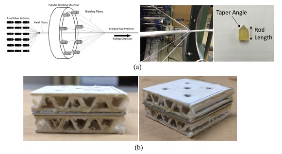
(a) Sketch and image of axial fiber bundles wrapped by braiding fiber bundles during the manufacturing process for fabricating rods, including a sample rod cut to length with a taper angle for compression testing; (b) Example of a sandwich structure prepared in this study consisting of corrugated cardboard, braided rods, and aluminum.
The braided preform was submerged in an epoxy resin bath and placed in a vacuum chamber oven at 80∘C for 20 minutes to lower the resin viscosity and facilitate impregnation of the fibers. Following the impregnation step, the wet fiber preform was hung vertically from inside the ceiling of an oven for curing. The braided structure was held taught with a weight throughout the cure cycle to ensure the rods are as straight as possible. Rods were cured at 175∘C for 4 hours. The fiber volume fraction of the composite rod is 61.7% and was determined by ignition method according to ASTM D3171 [35].
Cured glass fiber/epoxy rods were cut to a length of 6 mm, with a high-speed cutter and then one end of each rod was ground to produce a taper angle of approximately 45∘ by holding the rod tip at the correct inclination on the surface of revolving 800 grit paper on a polishing machine. An image of a braided glass rod for reinforcing the cardboard panels is also included in Figure 1(a), and the specifications for the rods are presented in Table 1 [25].
Braided glass fiber rod material specifications [25].
| Glass Fiber Bundle Tex (g/1000 m) | Number of Axial Fiber Bundles | Number of Braided Fiber Bundles | Braiding Angle (°) | Rod Cross Sectional Area, A (m2) | Fiber Volume Fraction (%) | Rod Density, ρ (g/m3) | Rod Specific Energy Absorption (kJ/kg) |
|---|---|---|---|---|---|---|---|
| 575 | 18 | 8 | 45 | 9.08 × 10⁻⁶ | 61.7 | 1.99 × 10⁶ | 68.9 |
The corrugated cardboard material for making the panels in this study was supplied by Daiwa Itagami Co. Ltd, Osaka, Japan. The cardboard is 6 mm thick and was cut to size with a high-speed cutter. Prior to inserting the rods, a 3.4 mm diameter hole was drilled through the cardboard. White carpenter’s glue was applied inside the hole and on the surface of the rod, and the rod was carefully pushed inside.
Aluminum sheets 1 mm in thickness were also cut to the same aerial dimensions as the cardboard and included in the compression panel structures as required. All cardboard and aluminum layers were bonded together with two-part epoxy resin. An example of a hybrid structure prepared in this study consisting of cardboard, braided rods, and aluminum is shown in Figure 1(b).
2.2 Mechanical characterization
Compression tests were performed on two-layer cardboard panels, and on five different hybrid panel structures involving two layers of cardboard with varying number and stacking order of thin aluminum sheets. Aluminum sheets were considered as structural supports for the cardboard due to its low cost and low density. Compression tests were also performed on structures with three and four layers of cardboard and two and three layers of aluminum, respectively, for the same number of composite rods. Finally, the effect of increased panel surface area was studied to confirm if this has a negative effect on the crushing performance since larger panels are a requirement for automotive structural applications. Progressive crushing behavior was evaluated fromthe compressive load-displacement curves, and the failure characteristics of these structures was examined visually.
Details on different hybrid sandwich structures are indicated in Table 2. Three replicates were tested for each panel configuration. In cardboard panels with rods, all rods were positioned according to the schematics of Figure 2. Different cases were also investigated with cardboard structures with and without rods and various stacking configurations of aluminum sheet as presented in Table 2. All panels were tested in compression in a Universal Testing Machine (Instron) with a 10-ton load cell at a cross-head speed of 1 mm/min. The samples were placed directly in the centre of the compression testing fixture. Compression tests were performed until the samples were completely crushed, marked by a rapid increase in load during final compaction.
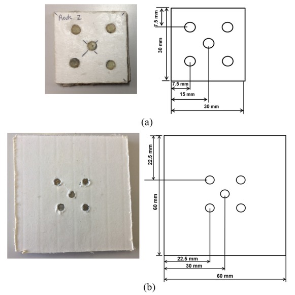
Dimensions and positions of rods in: (a) 30 mm × 30 mm cardboard panels; (b) 60 mm × 60 mm cardboard panels.
Compression testing panels.
| Panel stacking configuration, top to | Panel Aerial Dimensions (mm) |
| bottom | |
| C: Cardboard layer | |
| A: Aluminum layer | |
| CC | |
| CC + Rods | 30 × 30 |
| ACCA | |
| ACCA + Rods | 30 × 30 |
| ACAC | |
| ACAC + Rods | 30 × 30 |
| CACA | |
| CACA + Rods | 30 × 30 |
| CAAC | |
| CAAC + Rods | 30 × 30 |
| CAC | |
| CAC + Rods | 30 × 30, 60 × 60 |
| CACAC | |
| CACAC + Rods | 30 × 30, 60 × 60 |
| CACACAC + Rods | 30 × 30 |
3 Results and Discussion
3.1 Compression of two layers of cardboard panels
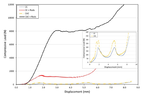
Typical compression load-displacement data of two-layer cardboard samples reinforced with and without rods is presented in Figure 3. In two-layer samples without rods, two peaks are observed with a maximum load of 200 N, corresponding to crushing of the individual cardboard layers in separate stages prior to final compaction. Images of the top layer being crushed first followed by the bottom layer of a two-layer cardboard structure are shown in Figure 4(a).
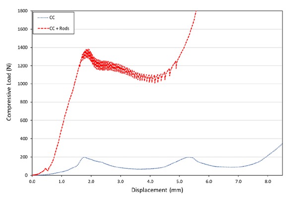
Load-displacement data of panels with two layers of cardboard (CC) with and without rods.
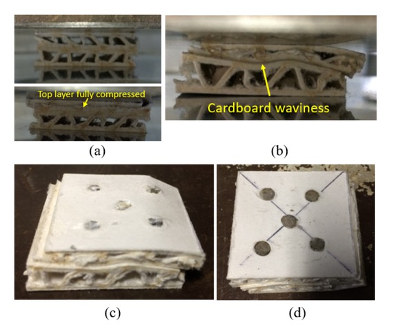
(a) Two-layer cardboard structure during compression testing; (b) two-layer cardboard panel with rods during compression testing; (c) top surface of two-layer cardboard panel with rods after compression testing; (d) bottom surface of two-layer cardboard panel with rods after compression testing.
Typical compression load-displacement data of two-layer cardboard samples reinforced with rods is also included in Figure 3. In these samples, the load increases to just below 1400 N, followed by a decrease to approximately 1000 N, after which the load increases rapidly during final compaction. Despite the presence of rods, the load is not constant and the panel does not exhibit progressive crushing behavior. Previous work by Fortin et al. [25] has shown
that single layer panels of the same cardboard material reinforced with the same type and configuration of rods can achieve a constant load just below 10 000 N, significantly greater than in these two-layer samples. An image of a two-layer cardboard panel with rods during compression testing
is shown in Figure 4(b). During crushing, significant waviness of the cardboard is observed where the top and bottom layers are in contact. Crushing of both layers is not uniform, and the top layer is also shifted considerably to the right. Crushing of the rods in both layers results in significant distortion of the cardboard in an unstable manner as seen by the waviness, resulting in the observed load-displacement curve with overall decreasing trend. Top and bottom surfaces of two-layer cardboard panels with rods after compression testing are shown in Figure 4(c) and (d). The top layer of cardboard has shifted relative to the bottom layer. Observation of the bottom surface of the rods in the lower layer also shows no signs of damage in the rods, due to cardboard layer shifting and so the cardboard with stands most of the loads.
3.2 Compression of two-layer cardboard and aluminum panels with and without rods
In an attempt to increase the thickness of the panel and the crushing distance when stacking two layers of cardboard with rods, modifications to the previous two-layer structure are required by incorporating 1 mm-thick aluminum sheets in various configurations within two layers of cardboard.
Typical compression load-displacement data for the five different cases of two-layer cardboard structures with and without rods and various stacking configurations of aluminum sheet are presented in Figures 5 to 9. The previously obtained results for two layers of cardboard with and without rods (CC and CC + Rods) are also included in all figures for comparison. In addition, the load-displacement data of panels without rods (with and without aluminum sheets) are also shown as a separate magnified graph for better interpretation.
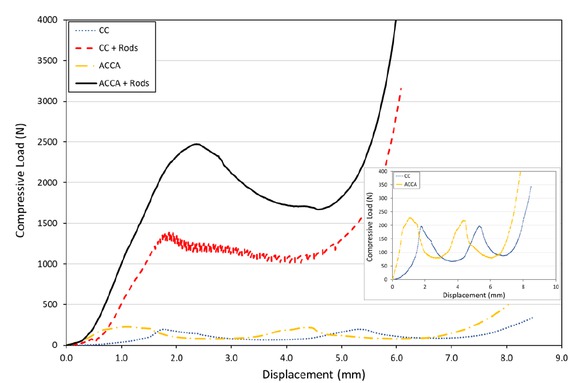
Load-displacement data of panels with two layers of cardboard (CC) with and without rods, and two-layers of cardboard and two layers of aluminum in a aluminum-cardboard-cardboard-aluminum stacking structure (ACCA) with and without rods.
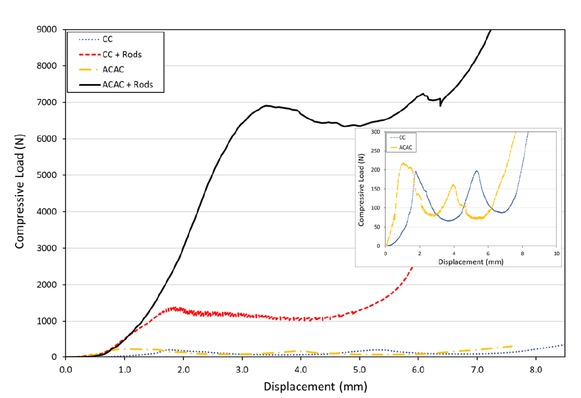
Load-displacement data of panels with two layers of cardboard (CC) with and without rods, and two-layers of cardboard and two layers of aluminum in a aluminum-cardboard-aluminum-cardboard stacking structure (ACAC) with and without rods.
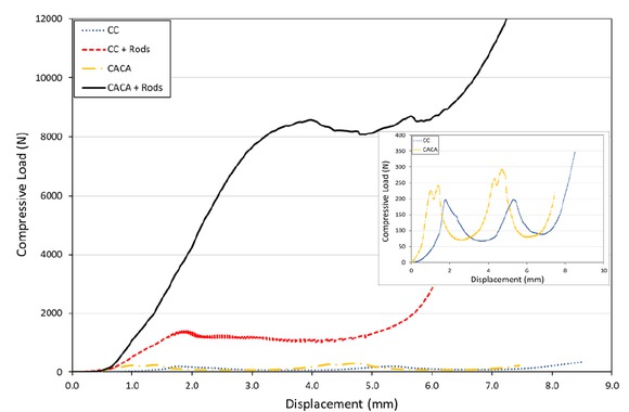
Load-displacement data of panels with two layers of cardboard (CC) with and without rods, and two-layers of cardboard and two layers of aluminum in a cardboard-aluminum-cardboard-aluminum stacking structure (CACA) with and without rods.
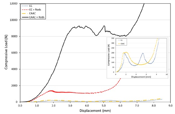
Load-displacement data of panels with two layers of cardboard (CC) with and without rods, and two-layers of cardboard and two layers of aluminum in a cardboard-aluminum-aluminum-cardboard stacking structure (CAAC) with and without rods.
Load-displacement data of panels with two layers of cardboard (CC) with and without rods, and two-layers of cardboard and one layer of aluminum in a cardboard-aluminum-cardboard stacking structure (CAC) with and without rods.
In the ACCA stacking configuration consisting of aluminum and cardboard only, the results are very similar to those of cardboard only (CC). When the aluminum sheets are located on the very top and bottom surfaces of the structure, they have no effect on the compression properties of the two-layer cardboard structure, as shown in Figure 5. Moreover, when rods are inserted in the cardboard layers, a maximum load of 2500 N is obtained after which the load then decreases to approximately 1700 N prior to final compaction, as shown in Figure 5. In this case, similar instability during crushing as observed in the CC + Rods sample occurs because the aluminum sheets on the top and bottom surfaces of the panel do not play a role in supporting the rods within the cardboard throughout crushing. For this reason, a constant load is not observed. However, the addition of aluminum sheets on the outer-most surfaces of the panels with rods (ACCA + Rods) does increase the strength compared with panels without aluminum(CC + Rods). This is likely due to the epoxy adhesive layer in between the aluminum and cardboard that further reinforces the cardboard on the outer surfaces of the panel, and possibly interacts with the splaying and fiber fragmentation modes of the rods. If the surrounding cardboard properties at the surface are changed due to epoxy impregnation in the paper fibers, splaying of glass fiber rods will also be affected. The effect of aluminum sheets and epoxy on the topmost and bottommost layers of the
panels will be explored in additional panel configurations presented in this section.
In the ACAC configuration with aluminum and cardboard only, the results are also very similar to those of CC. The addition of one layer of aluminum on the topmost and middle layers of the panel has negligible effect on the compression properties of the cardboard structure, as shown in Figure 6. Both cardboard layers fail in the same manner, regardless of the presence of aluminum. However, when rods are added to the structure (ACAC + Rods), a significant improvement in the maximum load value and its constant progressive behavior are observed. The maximum load obtained in this stacking configuration with rods is just below 7000 N, followed by a slight decrease to approximately 6200 N, and then a slight gradual increase prior to final compaction, as shown in Figure 6. The addition of an aluminum sheet in between the cardboard layers certainly plays an important role in providing stability to the rods in the panels when they are being compressed, and in ensuring that both layers of cardboard are crushed evenly with reduction in cardboard waviness and shifting of rods in adjacent layers.
For the CACA configuration, panels with no rods show similar results with CC samples as seen in previous samples. In the CACA + Rods structure, a maximum load of approximately 8050 N is attained, followed by a decrease to approximately 8000 N during crushing. Once again, the load is relatively constant and showing better signs of progressive crushing with one sheet of aluminum in between layers of cardboard, as shown in Figure 7. The maximum load is also higher compared with the previous ACAC + Rods as indicated in Figure 7 compared to that of Figure 6, suggesting that placement of one aluminum layer at the bottom as opposed to the top of the panel has benefits on the overall progressive crushing strength. In this case, when the aluminum layer is on the bottom, there is likely no effect on the behavior of the rods as splaying and fracture of the rods is initiated from the tapered tip on the top surface of a cardboard layer. When the aluminum sheet is placed on the top-most surface, the aluminum as well as the epoxy resin at the interface likely affect the mode of failure in the rods located in the top cardboard layer. Previous work by Fortin et al. [25] has shown that cardboard offers substantial benefits on the specific energy absorption of embedded rods, however, the interactions involved with aluminum stacking at the interface where rod splaying occurs likely have detrimental effects in this study. Common to the ACAC and CACA configurations is the aluminum in between cardboard layers that will surely have the same effect on the rods in the bottom layer. In the case of the CACA structure with a constant load just above 8000 N, this is still lower than the previously obtained value of 10 000 N by Fortin et al. [25] for 5 rods in a single layer of cardboard. During crushing, the aluminum sheet in between the cardboard layers will always warp slightly while supporting the rods, leading to some inefficiency in crushing energy. The interactions of the middle-layer of aluminum on the splaying mode of the underlying rods may also play a role in reducing the overall progressive crushing load, giving the results obtained in this study.
In the CAAC configuration without rods, the results are very similar to those of CC, once again as expected. In the CAAC + Rods panel, a maximum load of approximately 9000 N is obtained, however significant variation occurs as the load oscillates between 8000 N and 9000 N during crushing, as shown in Figure 8. Although the maximum load is greater, likely due to additional stiffness from inserting two layers of aluminum in between the cardboard layers, the noticeable variations in load cannot be ignored and are not desirable for progressive crushing where the load should be as constant as possible. The cause for the increased variation in load is unclear. From a practical standpoint of weight reduction for a given panel thickness, as there is no significant benefit in increasing the number of aluminum layers in between cardboard from one to two, it would be favorable to only insert one layer of aluminum. For very thick panels consisting of many layers, the weight savings can be significant.
In the final configuration, CAC, the panels with rods show very good progressive crushing at 8000 N. The load in these samples is highly constant, with very little variations, as shown in Figure 9. The CAC samples perform best out of all 5 stacking configurations. The results of this panel structure reaffirm that use of one sheet of aluminum in between cardboard layers offers desirable results. Differences in results between CAC and CACA are also not significant and therefore presence of the aluminum on the bottom-most surface likely has no effect. Furthermore, the CAC structure is better than the CACA and CAAC structures due to being of lower weight for a similar crushing performance, resulting in superior specific energy absorption.
Various stacking configurations of cardboard with aluminum have shown that it is certainly possible to increase the thickness and the associated crushing distance of single layers of cardboard reinforced with rods. Insertion of aluminum in between cardboard layers is most critical to provide stability in rods. Images of cardboard and aluminum panel configurations with and without rods after compression testing are shown in Figure 10.
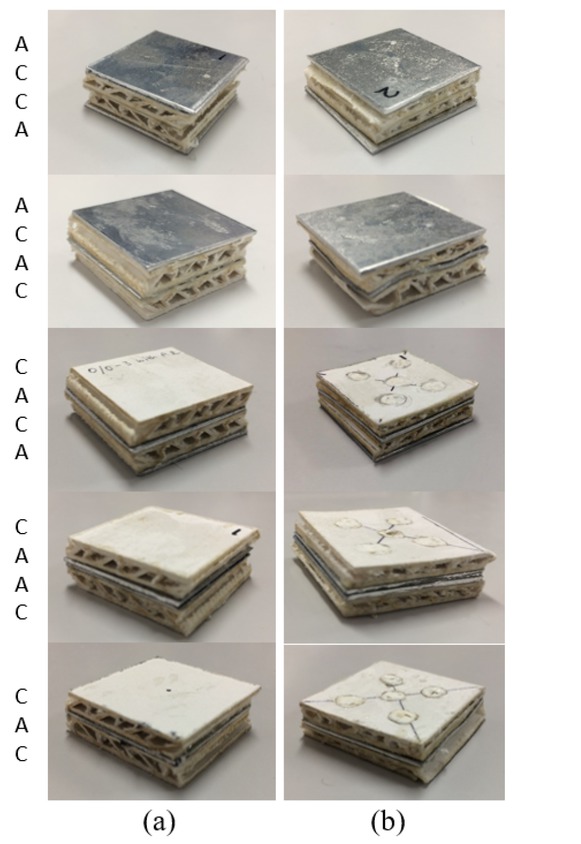
Images of cardboard and aluminum panel configurations after compression testing: (a) panels without rods; (b) panels with rods.
When comparing the results of two layers of cardboard and the best results from two layers of cardboard with aluminum, significant improvements are made. In multiple layers of cardboard without aluminum, the load of each rod is transferred directly to that of the adjacent layer. As the top of the rods is tapered and the bottom is flat, direct contact of over and underlying rods in this manner is not a stable condition for load transfer. This leads to rods being inclined from the vertical and distortion of layers during compression, represented in Figure 11(a). In multiple layers with aluminum, the load exerted on each rod is transferred to the aluminum support, and then transferred uniformly to the adjacent rods, as shown in Figure 11(b).
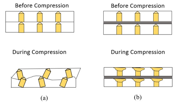
Sketches illustrating cardboard panels reinforced with rods without aluminum support (a) and with aluminum support (b) before and during compression. Aluminum support is required for effective load transfer and uniform crushing of adjacent layers.
3.3 Compression of multi-layered sandwich structures
Load displacement data of panels with three layers of cardboard and rods with one sheet of aluminum in between each layer (CACAC + Rods), and four layers of cardboard and rods with one sheet of aluminum in between in each layer (CACACAC + Rods) are presented in Figure 12. Data from panels with two layers of cardboard and one sheet of aluminum in between is also included for comparison. The maximum load for both three and four-layer cardboard panels is approximately the same at 6000 N, which is significantly less than that of CAC + Rods at 8000 N. For CACAC + Rods, the load oscillates by about 200-300 N with a mean load of 6000 N until final compaction. However for CACACAC + Rods, the load decreases gradually to 4500 N upon reaching a maximum. It is very clear that structures with both three and four layers of cardboard do not perform as well. Images of these multi-layered structures during and after compression are shown in Figure 13. In Figure 13(a), the layers are not uniformly crushed as seen by warpage of the aluminum sheets and shifting of the cardboard layers. The entire structure appears tilted in one direction. The same observations can be made in Figure 13(b). Crushing stability and uniformity that was observed with previous two-layers of cardboard and one aluminum sheet is no longer carried forward in these thicker panels. When the panels are relatively tall with a relatively small cross-sectional area, structural instability may be introduced during compression.
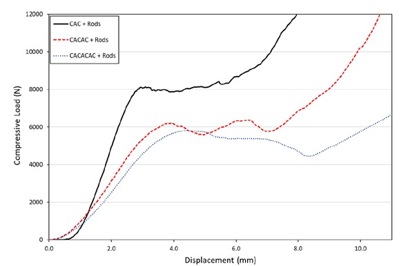
Load-displacement data of panels with two layers of cardboard and one layer of aluminum in between (CAC), three layers of cardboard with one layer of aluminum in between each cardboard layer (CACAC), and four layers of cardboard with one layer of aluminum in between each cardboard layer (CACACAC).
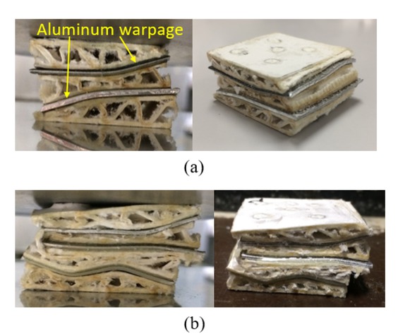
Images of multi-layered panel structures during and after compression testing: (a) CACAC panel structure; (b) CACACAC panel structure.
3.4 The effect of panel area on multi-layered sandwich structures
Load-displacement data of 30 mm × 30 mm and 60 mm × 60 mm panels with CAC and CACAC stacking configurations are presented in Figure 14. Data of panels without rods is shown in Figure 14(a), and that of panels with rods in Figure 14(b). The load-displacement data for both 30 mm × 30 mm CAC and CACAC are very similar, characterized by two maximum peaks, as shown in Figure 14(a).
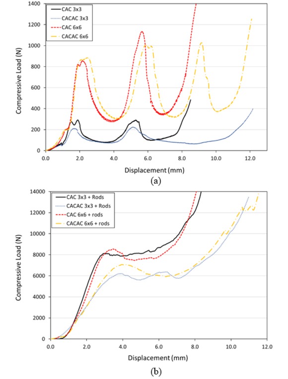
Load-displacement data of 3 cm × 3 cm and 6 cm × 6 cm panels with CAC and CACAC stacking configurations: (a) panels without rods and (b) panels with rods.
During compression of a two-layer cardboard structure, it was shown that each peak typically corresponds to crushing of an individual layer. In this case, three peaks are not seen in the CACAC structure with three layers of cardboard, as expected. However, in CACAC the onset of final compaction has been shifted to the right due to the increase in thickness. When the area of the panels is increased to 60 mm× 60 mm, the maximum load of all peaks increases and three peaks are now observed in the CACAC structure as opposed to two when the area is 30 mm × 30 mm. The reason for the difference in number of peaks as a function of area is presented in Figure 15(a) and (b). Figure 15(a) shows two-stage compression of a 30 mm × 30 mm CA- CAC sample where the top and bottom cardboard layers are compressed together first, followed by compression of the middle layer. However in Figure 15(b), three-stage compression of a 60 mm × 60 mm CACAC sample is shown where the bottom cardboard layer is compressed first, followed by the top layer, and finally the middle layer. The area clearly affects the strength of each cardboard layer, and influences the order and progression of cardboard layer collapse.
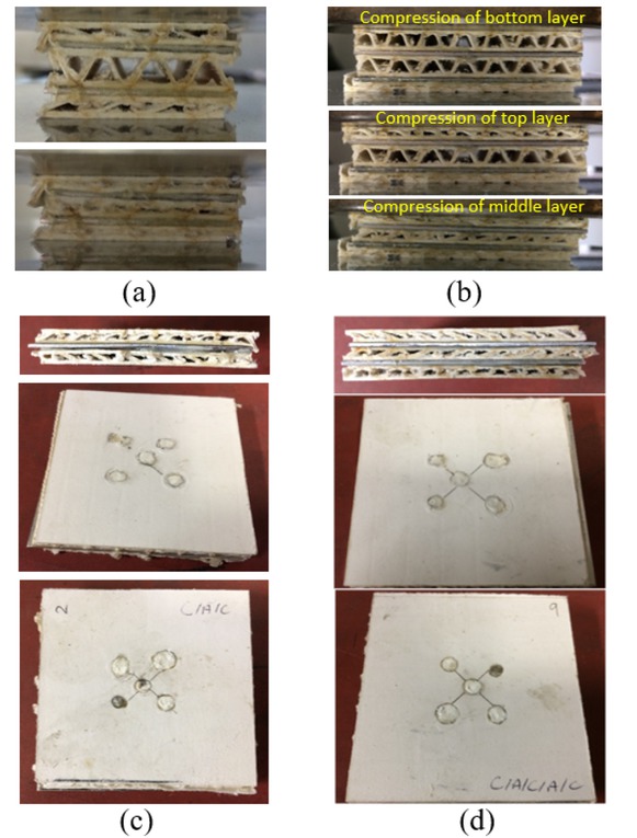
(a) Two-stage compression in a 30 mm × 30 mm CACAC sample showing the top and bottom cardboard layers compressed together first, followed by compression of the middle layer; (b) Three-stage compression in a 60 mm × 60 mm CACAC sample showing the bottom layer compressed first, followed by the top layer, and lastly the middle layer; (c) Side, top, and bottom views of a 60 mm × 60 mm CAC sample; (d) Side, top, and bottom views of a 60 mm × 60 mm CACAC sample.
In Figure 14(b), results show that increasing the area of panels does not have a negative effect on their performance. As observed previously, the panels that perform best are the CAC configuration. CAC with an area of 60 mm × 60 mm shows a maximum load that is slightly higher, however the load then decreases slightly below that of the 30 mm × 30 mm CAC throughout most of the crushing. It should also be noted that in both areal dimensions, the locations and spacing of the rods were unchanged. Side, top, and bottom views of a 60 mm× 60 mm CAC sample after compression are shown in Figure 15(c).
When comparing the effect of area on CACAC structures, oscillations of the load just above and below 6000 N throughout crushing are seen with a smaller area. When the area is increased, the maximum load reached increases to approximately 7000 N, but then gradually decreases to 6000 N. A decreasing load is likely caused by factors other than the panel area such as misalignment of rods. One thing that is certain is that the load oscillations in the CACAC structure with a smaller area are not desirable for progressive crushing. Once again, the locations and spacing of the rods in both panel areas were kept the same, and additional tests to investigate their effects are required. Side, top, and bottom views of a 60 mm × 60 mm CACAC sample after compression are shown in Figure 15(d).
4 Conclusions
Static compression testing was performed on stacked layers of cardboard reinforced with braided glass fiber rods, and the effect of aluminum sheets in various locations in panels with two layers of cardboard was investigated. Thicker panels with three and four layers of cardboard and aluminum sheets were then tested, based on the optimal stacking configuration in the two-layer panels. The effect of panel area on crushing performance was also considered. This study showed that:
Two layers of cardboard with rods that are stacked on top of each other with no additional support results in poor crushing performance due to instability of the rods and non-uniform deformation of the cardboard layers.
A stacking configuration with two layers of cardboard and one aluminum sheet in between (CAC structure) gives the best results out of all five cases studied, in terms of progressive crushing and weight reduction. The aluminum was successful in allowing for uniform crushing of individual cardboard layers and rods while increasing the crushing distance compared with a single layer of cardboard. Aluminum sheet is relatively lightweight and inexpensive, making it a suitable material for stacking of braided rod-reinforced cardboard panels for increasing thickness as required in automotive structures.
Panels of increased thickness with three and four layers of cardboard and two and three layers of aluminum, respectively, do not crush well as the structures become unstable when the thickness (number of layers) of the panel becomes noticeably greater for a relatively small surface area.
Increasing the surface area of panels without changing the number and positioning of rods has no adverse effect on the crushing performance of panels. However, improvements to the performance of multi-layer panels with three or more layers must be achieved.
Acknowledgements
The authors would like to acknowledge Mr. Tadashi Uozumi and Dr. Akio Ohtani from Gifu University for their technical support in the operation of the braiding machine.
Declaration of conflicting interests:
The authors declare that there is no conflict of interest.
Funding:
This research received no specific grant from any funding agency in the public, commercial, or not-for-profit sectors.
References
[1] International Organization of Motor Vehicle Manufacturers. World Motor Vehicle Production by Country and Type OICA correspondents survey, Paris, 2018.Search in Google Scholar
[2] Hull D and Clyne T. An Introduction to Composite Materials 2nd ed. Cambridge: Cambridge University Press, 1996, p. 2.10.1017/CBO9781139170130Search in Google Scholar
[3] Thornton PH. Energy Absorption in Composite Structures. J Compos Mater 1979; 13(3): 247-262.10.1177/002199837901300308Search in Google Scholar
[4] Thornton PH. Effect of trigger geometry on energy absorption of composite tubes. In: Proceedings of the 5thInternational Conference on Composite Materials (ICCM/5) San Diego, USA, 29 July–1 August 1985. pp. 1183-1199. Warrendale, PA: Metallurgical Society.Search in Google Scholar
[5] Hull D. Energy Absorption of Composite Materials under Crash Conditions. In: Hayashi T, Kawata K and Umekawa S (eds) Progress in Science and Engineering Composites Tokyo, 1982, pp.861-870.Search in Google Scholar
[6] Hull D. Axial crushing of fiber reinforced composite tubes. In: Jones N and Wierzbicki T (eds) Structural Crashworthiness London: Butterworths, 1983, pp.118-135.Search in Google Scholar
[7] Hull D and Coppola JC. Effect of trigger geometry on crushing of composite tubes. In: Benson S, Cook T, Trewin E. (eds) Materials and Processing—Move into the 90’s. Amsterdam: El-sevier, 1989, pp.29-38.Search in Google Scholar
[8] Hull D. A Unified Approach to Progressive Crushing of Fibre-Reinforced Composite Tubes. Compos Sci Technol 1991; 40(4): 377-421.10.1016/0266-3538(91)90031-JSearch in Google Scholar
[9] Fairfull AH and Hull D. Effects of specimen dimensions on the specific energy absorption of fiber composite tubes. In: Mathews FL et al. (eds) Proceedings of ICCM and ECCM, Vol. 3. London: Pergamon Press, 1987, pp.3.36-3.45.Search in Google Scholar
[10] Fairfull AH and Hull D. Energy absorption of polymer matrix composite structures: frictional effects. In:Wierzbicki T and Jones N (eds) Structural Failure New York: Wiley, 1989, pp.255-279.Search in Google Scholar
[11] Hamada H, Coppola JC, Hull D. Comparison of energy absorption of carbon/epoxy and carbon/PEEK composite tubes. Composites 1992; 23(4): 245-252.10.1016/0010-4361(92)90184-VSearch in Google Scholar
[12] Hamada H, Kameo K, Sakaguchi M. Energy- absorption properties of braided composite rods. Compos Sci Technol 2000; 60(5): 723-729.10.1016/S0266-3538(99)00182-7Search in Google Scholar
[13] Yang Y, Ahmed K, Zhang R. A study on the energy absorption capacity of braided rod composites. Compos Struct 2018; 206: 933-940.10.1016/j.compstruct.2018.08.077Search in Google Scholar
[14] Ma Y, Sugahara T, Yang Y. A study on the energy absorption properties of carbon/aramid fiber filament winding composite tube. Compos Struct 2015; 123: 301-311.10.1016/j.compstruct.2014.12.067Search in Google Scholar
[15] Xu J, Ma Y, Zhang Q. Crashworthiness of carbon fiber hybrid composite tubes molded by filament winding. Compos Struct 2016; 139: 130-140.10.1016/j.compstruct.2015.11.053Search in Google Scholar
[16] Kathiresan M, Manisekar K, Manikandan V. Crashworthiness analysis of glass fibre/epoxy laminated thin walled composite conical frusta under axial compression. Compos Struct 2014;108: 584-99.10.1016/j.compstruct.2013.09.060Search in Google Scholar
[17] Sun G, Li S, Liu Q. Experimental study on crashworthiness of empty/aluminum foam/honeycomb-filled CFRP tubes. Compos Struct 2016; 152: 969-93.10.1016/j.compstruct.2016.06.019Search in Google Scholar
[18] Wang Y, Feng J, Wu J. Effects of fiber orientation and wall thickness on energy absorption characteristics of carbon-reinforced composite tubes under different loading conditions. Compos Struct 2016; 153: 356-68.10.1016/j.compstruct.2016.06.033Search in Google Scholar
[19] Atthapreyangkul A, Prusty BG. Experimental and numerical analysis on the geometrical parameters towards the maximum SEA of CFRP components. Compos Struct 2017; 164: 229-36.10.1016/j.compstruct.2016.12.078Search in Google Scholar
[20] Eshkoor RA, Oshkovr SA, Sulong AB. Effect of trigger configuration on the crashworthiness characteristics of natural silk epoxy composite tubes. Compos Part B-Eng 2013; 55: 5-10.10.1016/j.compositesb.2013.05.022Search in Google Scholar
[21] Alkbir MFM, Sapuan SM, Nuraini AA. Fibre properties and crashworthiness parameters of natural fibre-reinforced composite structure: A literature review. Compos Struct 2016; 148: 59-73.10.1016/j.compstruct.2016.01.098Search in Google Scholar
[22] Alia RA, Cantwell WJ, Langdon GS. The energy-absorbing characteristics of composite tube-reinforced foam structures. Compos Part B-Eng 2014; 61: 127–135.10.1016/j.compositesb.2014.01.018Search in Google Scholar
[23] Alia RA, Guan ZW, Jones N. The energy-absorption characteristics of metal tube-reinforced polymer foams. J Sandw Struct Mater 2015; 17(1): 74-94.10.1177/1099636214554597Search in Google Scholar
[24] Alia RA, Guan ZW, Cantwell WJ. A numerical study of the energy-absorption characteristics of metal tube reinforced polymer foams. J Sandw Struct Mater 2016; 18(5): 597-623.10.1177/1099636215603035Search in Google Scholar
[25] Fortin GY, Elbadry EA, Hamada H. Crashworthiness of cardboard panels reinforced with braided glass fiber rods for vehicle side impact protection. J Reinf Plast Comp. Advanced online publication. doi: 10.1177/073168441879656010.1177/0731684418796560Search in Google Scholar
[26] Paruka P, Siswanto WA, Maleque MA. Crashworthy capacity of a hybridized epoxy-glass fiber aluminum columnar tube using repeated axial resistive force. J Mech Sci Technol 2015; 29(5): 1941-1953.10.1007/s12206-015-0415-4Search in Google Scholar
[27] Paruka P, Yasin MHM,Mamat R. Performance Properties of Hybrid Aluminum-Composite Columnar Tube under Axial Crush Force. Adv Mat Res 2015; 1115: 288-291.10.4028/www.scientific.net/AMR.1115.288Search in Google Scholar
[28] Harms V, Harhash M, Carrado A. Energy Absorption Behavior of Metal/Polymer/Metal Sandwich Crash Structures. Key Eng Mat 2017; 746: 275-281.10.4028/www.scientific.net/KEM.746.275Search in Google Scholar
[29] Shin KC, Lee JJ, Kim KH. Axial crush and bending collapse of an aluminum/GFRP hybrid square tube and its energy absorption capability. Compos Struct 2002; 57: 279-287.10.1016/S0263-8223(02)00094-6Search in Google Scholar
[30] Reuter C, Tröster T. Crashworthiness and numerical simulation of hybrid aluminum-CFRP tubes under axial impact. Thin Wall Struct 2017; 117: 1-9.10.1016/j.tws.2017.03.034Search in Google Scholar
[31] Kim HC, Shin DK, Lee JJ. Crashworthiness of aluminum/CFRP square hollow section beam under axial impact loading for crash box application. Compos Struct 2014; 112: 1-10.10.1016/j.compstruct.2014.01.042Search in Google Scholar
[32] Liu Q, Mo Z, Wu Y. Crush response of CFRP square tube filled with aluminum honeycomb. Compos Part B-Eng 2016; 98: 406-414.10.1016/j.compositesb.2016.05.048Search in Google Scholar
[33] Wu Y, Liu Q, Fu J. Dynamic crash responses of bio-inspired aluminum honeycomb sandwich structures with CFRP panels. Compos Part B-Eng 2017; 121: 122-133.10.1016/j.compositesb.2017.03.030Search in Google Scholar
[34] Zhu G, Sun G, Liu Q. On crushing characteristics of different configurations of metal-composites hybrid tubes. Compos Struct 2017; 175: 58-69.10.1016/j.compstruct.2017.04.072Search in Google Scholar
[35] ASTM D3171-15, Standard Test Methods for Constituent Content of Composite Materials, ASTM International, West Conshohocken, PA, 2015, www.astm.orgSearch in Google Scholar
© 2019 Gabriel Y. Fortin et al., published by De Gruyter
This work is licensed under the Creative Commons Attribution 4.0 Public License.
Articles in the same Issue
- Analysis on the impact response of fiber-reinforced composite laminates: an emphasis on the FEM simulation
- Artificial neural network for predicting the flexural bond strength of FRP bars in concrete
- Cyclic behavior of GFRP strengthened infilled RC frames with low and normal strength concrete
- Durability of basalt fiber-reinforced polymer bars in wet-dry cycles alkali-salt corrosion
- Effect of B4C particle size on the mechanical properties of B4C reinforced aluminum matrix layered composite
- Enhanced dielectric properties of BaTiO3 ceramics with cerium doping, manganese doping and Ce-Mn co-doping
- Free and forced vibration analysis of rectangular/circular/annular plates made of carbon fiber-carbon nanotube-polymer hybrid composites
- Influence of nano-SiO2 on the bonding strength and wear resistance properties of polyurethane coating
- Investigation of wear behavior of nanoalumina and marble dust-reinforced dental composites
- Negative effect of clay fillers on the polyvinyl alcohol biodegradation: technical note
- Photocatalytic activity of Cu2O/ZnO nanocomposite for the decomposition of methyl orange under visible light irradiation
- Sub-surface mechanical properties and sub-surface creep behavior of wood-plastic composites reinforced by organoclay
- Surface integrity in wire-EDM tangential turning of in situ hybrid metal matrix composite A359/B4C/Al2O3
- The influence of the WC-Co composite microstructure model on stress field heterogeneity at the microstructure level: FEM based study
- Vibration-damping characterization of the basalt/epoxy composite laminates containing graphene nanopellets
- A review on nanocomposite hydrogels and their biomedical applications
- Optimization and simulation analysis of structure parameters of OPCM ultrasonic longitudinal wave actuating element
- Research Article
- Preparation of POSS-triol/wollastonite composite particles by Liquid phase mechanochemical method and its application in UV curable coatings
- Research on preload relaxation for composite pre-tightened tooth connections
- Dough moulding compound reinforced silicone rubber insulating composites using polymerized styrene butadiene rubber as a compatibilizer
- Hydration And Microstructure Of Astm Type I Cement Paste
- Effects of NiO content on the microstructure and mechanical properties of AgSnO2NiO composites
- Overall buckling behaviour of laminated CFRP tubes with off-axis ply orientation in axial compression
- UV sensing optode for composite materials environment monitoring
- On crushing characteristics of hybrid sandwich aluminum-cardboard panels reinforced with glass fiber composite rods
- Preparation and characterization of Ni-Cu composite nanoparticles for conductive paints
- A research on the preparation of oil-adsorbing hydrophobic porous resins by high internal phase emulsions (HIPEs) template
- Material characteristics of random glass-mat-reinforced thermoplastic under cryogenic thermal cycles
- Differentiation of non-black fillers in rubber composites using linear discriminant analysis of principal components
- Research Article
- Efficiency of TiO2 catalyst supported by modified waste fly ash during photodegradation of RR45 dye
- Synthesis and performance of polyurethane/silicon oxide nano-composite coatings
- Study on preparation of magnesium-rich composite coating and performance enhancement by graft modification of epoxy resin
- Research Article
- Mechanical and wear properties of polyetheretherketone composites filled with basalt fibres
- Mechanical Properties of Al 25 wt.% Cu Functionally Graded Material
- Research Article
- Weight reduction of a carbon fibre composite wheel
- Synthesis, electrical properties, and kinetic thermal analysis of polyaniline/ polyvinyl alcohol - magnetite nanocomposites film
- Seismic Behaviour of TRC-Strengthened RC Columns under Different Constraint Conditions
- Characterization of neat and modified asphalt binders and mixtures in relation to permanent deformation
- Microstructures, interface structure and room temperature tensile properties of magnesium materials reinforced by high content submicron SiCp
- Research Article
- Effect of Cutting Temperature on Bending Properties of Carbon Fibre Reinforced Plastics
- Mechanical and tribological properties of B-C-N coatings sliding against different wood balls
- Thermal conductivity of unidirectional composites consisting of randomly dispersed glass fibers and temperature-dependent polyethylene matrix
- Effects of Waste Eggshells addition on Microstructures, Mechanical and Tribological Properties of Green Metal Matrix Composite
- Investigation of porosity effect on flexural analysis of doubly curved FGM conoids
- Review Article
- Utilization of tailings in cement and concrete: A review
- Research Article
- Equivalent stiffness prediction and global buckling analysis using refined analytical model of composite laminated box beam
- Mechanochemical synthesis of zincite doped with cadmium in various amounts
- Size-dependent vibration analysis of graphene-PMMA lamina based on non-classical continuum theory
- Automated, Quality Assured and High Volume Oriented Production of Fiber Metal Laminates (FML) for the Next Generation of Passenger Aircraft Fuselage Shells
- Research Article
- An investigation of the stitching effect on single lap shear joints in laminated composites
- The low-velocity impact and compression after impact (CAI) behavior of foam core sandwich panels with shape memory alloy hybrid face-sheets
- Effect of granulometric distribution on electromagnetic shielding effectiveness for polymeric composite based on natural graphite
- The enhancement of filament winding in marine launching rubber gasbag
- Research on ELID Grinding Mechanism and Process Parameter Optimization of Aluminum-Based Diamond Composites for Electronic Packaging