Hygrothermal environment effect on the critical buckling load of FGP microbeams with initial curvature integrated by CNT-reinforced skins considering the influence of thickness stretching
-
Mohammad Alkhedher


Abstract
Due to the need for structures with refined properties to bear against different loading conditions, recently, carbon nanotubes (CNTs) have been used widely to reinforce them. The extremely high stiffness of CNTs makes them significant as one of the best reinforcements to improve the mechanical behaviors of structures. This work focuses on microbeam buckling response with an initial curvature that includes three layers. The mid-layer that is known as the core is constituted of functionally graded porous (FGP) materials and two CNT-reinforced composite skins are bonded to the core to integrate it. The whole structure is affected by the hygrothermal environment and springs and shear layers are put below it. For the first time, for such a structure, a refined shear deformation theory (RSDT) as a higher-order theory that considers thickness stretching effect in polar coordinates is used that presents more accurate results, especially for deeply curved beams. Modified couple stress theory (MCST) in combination with the virtual displacement principle is utilized to establish the governing equations. The obtained results demonstrate the significance of porosity percentage and CNTs’ addition to the skins on the critical nanotubes buckling load. Also, the different behaviors of the microstructure at various temperatures are analyzed and discussed in detail.
1 Introduction
Nowadays, scientists are searching for ways to improve the mechanical behaviors of different kinds of structures against different loading conditions to get the desired response. Nevertheless, with the traditional materials and structures, reaching this aim is not possible. Therefore, the researchers were motivated to try different combinations of both materials and structures to analyze their mechanical behaviors [1,2,3,4,5,6,7,8,9]. One of these ways is using composite materials. Composites due to their more proper specifications are used for decades [10], but they have limitations too. Using nanofillers as the second phase of the composite is one of the most appropriate ways to reinforce the structures. These kinds of composites that are reinforced by nanofillers are known as nanocomposites [11,12,13,14,15]. The nanofillers are distributed within the matrix by different methods [16]. Among the different kinds of nanofillers, carbon nanotubes (CNTs) attracted researchers more than others due to their unique properties as high stiffness, sound and energy-absorbing specifications, thermal conductivity, and are known for their electromagnetic characteristics [17,18,19]. It may be interesting to know that CNTs were discovered first by Iijima in 1991 [20]. After that, the rapid development of CNT studies has occurred and different aspects of their specifications are considered by many authors [21,22,23,24,25,26,27,28]. Also, another way to improve the behavior of the structures is to use several layers together. This kind of structure is usually called sandwich structure and includes a mid-layer or a core, and two skins that are bonded to the core. The use of sandwich structures leads to reach approximately the desired results. It is noteworthy that the core of the sandwich is selected in such a way that it is softer than the skins. Also, its thickness is much more than that of skins. In the field of these kinds of engineering structures, researchers are publishing their new findings [29,30,31,32,33,34,35,36]. As an instance, vibration analysis of a CNT-reinforced composite plate was performed by Zhu et al. [37]. They applied the finite element analysis by using the first-order shear deformation plate theory (FSDT). They considered different types of CNT distributions and boundary conditions. In another study, the effect of piezoelectric actuators that were fully bonded to a porous core on the vibrational behavior of the system was considered by Arshid and Khorshidvand [38]. Loghman and Cheraghbak [39] addressed agglomeration effects on the behavior of the nanocomposite of the piezoelectric cylinder. They assumed that the structure was under internal pressure and CNTs were selected as the reinforcement. A refined mixture rule was used by Mirzaei and Kiani [40] to analyze cylindrical panels made from functionally graded-CNT (FG-CNT)-reinforced composites. They investigated the different effects of CNTs on the results. Stability analysis of the three-phase sandwich panels that were nonlinearly imperfect was presented by Thu and Duc [41]. Using the Ritz numerical approach, Selim et al. [42] attained natural frequencies of FG-CNT-reinforced composites plates. They included the thermal effects on the results and investigated the uniform and FG distribution of CNTs and presented their results. The dynamic response of the piezoelectric FG sandwich cylindrical shells was investigated by Nguyen [43] considering the shear deformation effect. Also, Mehar et al. [44] applied a finite element method to solve the nonlinear equations of a doubly curved FGCNT-reinforced composites shell. The structure was modeled by using higher-order shear deformation theory with Green–Lagrange strains. Yas and Samadi [45] explored the CNT-reinforced composite Timoshenko beams by investigating the vibration response and buckling load using the extended rule of the mixture to achieve effective properties.
In recent years, many kinds of research have illustrated that when the characteristic length scale related to nonuniform plastic deformation is in the micro/nanoscale, materials show strong size effects [46,47,48,49,50]. The theories of classical plasticity cannot be used to calculate this size dependence of material behavior at small scales because their constitutive models do not possess an inner length scale. Since investigating the size-dependent mechanical behavior of nano/microscaled structural systems can deliver important statistics for designers of micro/nanoscaled mechanisms, some macroscopic continuum mechanics were effectively industrialized and selected to evaluate the size-dependent effect. Thus, to give details about the size effects, developing strain gradient theory for small-scale devices is required [51,52,53]. Utilizing strain gradient theory, Hosseini et al. [54] analyzed various stress distributions in single-wall carbon nanotubes (SWCNTs) under internal pressure to obtain the size-dependent behavior of SWCNTs. Malikan and Nguyen [55] obtained buckling of piezo-magneto-electric nanoplates in a hygro-thermal atmosphere by applying the higher-order nonlocal strain gradient theory and a new variable plate method. Imani Aria and Biglari [56] proposed a nonlocal strain gradient model to investigate vibrational responses and buckling of microtubules utilizing the finite element method to investigate different size effect parameters. Arshid et al. [57] used the modified couple stress theory (MCST) to analyze both vibrational response and buckling behavior of curvy microbeams. Their under consideration model was composed of a porous core that was embedded between two nanocomposite patches. MCST was used by Jouneghani et al. [58] to analyze nonuniform composite laminated beams based on the Ritz formulation. They used Euler–Bernoulli beams theory to describe the displacements. Also, hygrothermal modeling of the buckling behavior of sandwich plates with nanocomposite face sheets resting on a Pasternak foundation was provided by Kiarasi et al. [59]. Soltani et al. [60] presented their study about the nonlocal elasticity theory for lateral stability of tapered thin-walled nanobeams with axially varying materials. In another study, Karami et al. [61] analyzed nonlocal buckling of composite curved beams, which were reinforced with FGCNTs. Size-dependent free vibrations of the FG polymer composite curved nanobeams reinforced with nanocomposite resting on Pasternak foundations were investigated by Arefi et al. [62]. It should be noted that they used the Cartesian coordinate system to perform their study, which may lead to inaccurate results, especially for higher values of the central angle. To overcome this shortcoming of the use of the Cartesian coordinate system, recently, the authors have been trying to analyze curved beams via the polar coordinate system. Sobhy [63] in his published work has used the polar coordinate system, natural frequencies, and critical buckling loads of a multilayer curved beam. He proved that at higher values of the central opening angle, the obtained results using the Cartesian system are not accurate as of the polar system. The influence of thickness stretching was taken into account by Talebizadehsardari et al. [64] to analyze wave features of a curved graphene-reinforced beam. In another work, Arshid and Amir [65] used a similar system using higher-order shear deformation theory, considering the effect of graphene platelets reinforcement on the frequency response of a curvy microbeam.
The literature review has shown that the buckling response of microbeams is not well investigated with initial curvatures that are composed of three multilayers of functionally graded porous (FGP) core with two CNT-reinforced composite skins. The whole structure is affected by both temperature and moisture variations. To obtain reliable results of the central opening angle, a refined shear deformation theory (RSDT) as a higher-order theory capable of considering the thickness stretching effect is used in the polar coordinates to represent the displacements of the microstructure. Also, MCST that uses a length-scale parameter is used to investigate the scale influence. The governing equations are initiated using virtual displacements and variational approaches and then solved analytically. The results are presented based on various parameters’ variations and discussed in detail. The novelty of the present work lies in considering the three-layered curved microbeam in polar coordinates with such a layer arrangement and, also, in the hygrothermal environment. The findings of this work will help in designing and creating more optimal engineering and structures, especially those that have curvature.
2 Basic relations
2.1 Model description
As shown in Figure 1, a three-layered microbeam with an initial curvature composed of two skins and a core is considered. The core of the microstructure is made of FGP materials that consist of pores; while the top and bottom layers are CNT-reinforced composites that have the role of integration of the whole structure. The whole structure is affected by both moisture and temperature variations and lay on an elastic base that is modeled by the Pasternak foundation type. The geometrical parameters of the microbeam, namely its central opening angle and curvature mid-radius, are given by β and R, respectively. Also, the thickness of each layer is h i (i = f for the skins; i = c for the core).
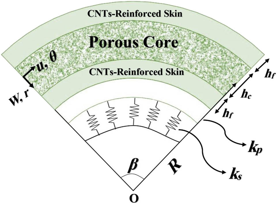
Configuration of the under investigation microbeam with initial curvature.
2.2 Constitutive law
As mentioned earlier, the core and the skins of the curved microbeam are composed of FGP and CNT-reinforced composite materials, respectively. The constitutive law for both the core and skins in the presence of hygrothermal effect can be written as follows [66]:
The superscripts c and f denote the core and skins, respectively. α ij (r) and β ij (r) are the thermal and moisture expansion coefficients, respectively, which vary through the thickness of the layers, the temperature and moisture changes are given by ΔT and ΔH, while Q ijkl are the stiffness components that can be determined for the FGP core via the following relations [67]:
E c(r) is Young’s elasticity modulus and ν c represents the core Poisson’s ratio. As it is clear, Young’s elasticity modulus depends on the thickness variation. Therefore, its variations obey different functions and depend on the patterns of pores’ placement. If the pores are considered to be distributed symmetrically throughout the core’s thickness (which is known as the “even” pattern in this article), the following relation may be used to express this distribution and show its effect on the elasticity modulus [68]:
For “uneven” porosity pattern, the pores are considered as distributed asymmetrically concerning the core’s midplane and in the “uniform” pattern, they are independent of thickness [52,69]:
in which
In the above relations, e 1 is the porosity and changes between 0 to 100%. This dimensionless parameter shows the void to the bulk volume and its increment shows the increase of the void volume.
In addition to thickness, the properties of the FGP core also depend on the temperature changes. It means that the core’s properties vary with changes in temperature. To consider this effect, the following relation is suggested by the previous studies for the temperature dependency of the SUS304 FGP core [67]:
where P c represents the core’s properties and T is the temperature (K), and P i (i = 0, 1, 2) coefficients are dependent on the temperature.
Furthermore, to describe stiffness components Q ij for the CNT-reinforced composite skins, the following relations can be used [70]:
Similar to the FGP core, the skins’ Young’s modulus also depends on both the thickness and temperature. First, its dependency on thickness is considered. The following relations show the effective properties of CNT-reinforced composite skins [57,67]:
where the longitudinal and shear Young’s moduli of CNTs and matrix are given by
CNTs’ efficiency parameters based on their volume fractions obtained by MDS [71]
| CNTs’ volume fraction | η 1 | η 3 |
|---|---|---|
| 0.11 | 0.149 | 0.934 |
| 0.14 | 0.150 | 0.941 |
| 0.17 | 0.149 | 1.381 |
Throughout the article, m refers to the matrix of the skins. The hygrothermal properties of the skins can be obtained via RM with the following relation [72]:
Also, for Poisson’s ratio, the following relation hold [73]:
In the above relation, the volume fraction of CNTs is given by
where w
CNT represents the mass density of reinforcements and CNTs and the matrix densities are given by
Five different patterns for the CNT distribution, namely UU, FG-VA, FG-XX, and FG-OO, are considered in this work. The following relations hold for each of the mentioned distribution patterns [66,75]:
In the above relations, i = t, b where t and b denote top and bottom skins. Also, for the upper skin, a plus sign and for the lower skin, a minus sign is used. The mentioned patterns are shown in the cross-sectional view of the beam in Figure 2.
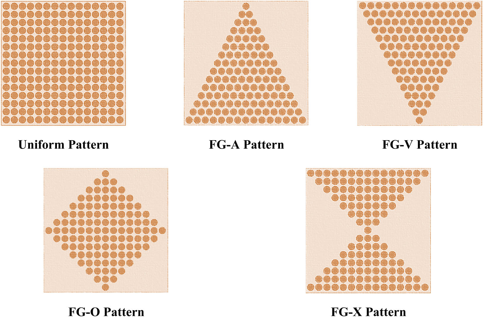
Various distribution patterns of CNTs across the skins’ thickness.
Next, the temperature dependency of the skins is considered. The skins are made from polymethyl methacrylate (PMMA), which is reinforced by CNTs. The polynomial function considered for CNTs reinforcement dependence to temperature is as follows [76]:
where P 1, P 2, and P 3 are coefficients that represent the dependence of the CNT properties on the temperature.
2.3 Derivation of the equations
To analyze the aforementioned microstructure, for the first time, the polar coordinate system is used, especially for deeply curved beams. The origin of this polar coordinate system lies on the left corner side of the microstructure’s midplane. Also, the displacement components of its arbitrary point are described based on a novel RSDT, which considers the thickness stretching effect that, again, results in more reliable values compared to the theories that neglect this effect. Therefore, the strain components of an arbitrary point using RSDT are demonstrated as [63]
In the above relations, the displacements of the microplate’s midlayer in axial and transverse directions are, respectively, given by u and w and ψ and φ are additional displacements. Also, f(r) is the shear deformation function that obeys the following relation based on RSDT:
where h is the total thickness of the structure. The variational approach and the virtual displacement principle were applied [77]:
In the above equation, U c and U m are, respectively, the classical and nonclassical strain energies and the work of externally applied loads is shown by W.
The total strain energy (i.e., U c + U m) of the under consideration curved microbeam is given by U T and includes those of the core and skins; therefore [78],
As noted previously, the MCST is used to demonstrate the scale influence on the critical buckling load of the microstructure. In equation (19),
In the above equations, λ (=E/2(1 + ν)) is Lame’s parameter and δ ij is the Kronecker delta.
Also, μ
m is the length-scale parameter relevant to the symmetric rotation gradients
This leads to obtaining the nonzero terms as
To calculate variations of the total strain energy, the following relation is obtained:
In this study, the external work includes three terms: the first term is related to the Pasternak foundation, the second one is attributed to the applied in-plane loads, and the third is due to the hygrothermal loads.
As expressed before, the microstructure was rested on an elastic foundation bearing both normal and shear loads using springs and shear layers, respectively. Consequently, the work of this foundation is applied to the structure’s lower surface and can be determined by [80]
where k
s and k
p are Pasternak foundation moduli that relate to the springs and shear layer, respectively. Also,
To obtain the work applied by the in-plane load, the following expression may be employed [81]:
and the variation of the hygrothermal load work can be evaluated by equation (26) [82]:
in which N TH = N Hygro + N Thermo [83] with
Differential governing equations can be achieved by inserting the derived terms for strain energy variations and the work applied by external loads in the virtual displacement relation, equating expressions for each coefficient to zero, which leads to the following equations:
in which
Rewriting the above classical and higher-order stress resultants as a function of displacements and substituting in the derived governing equations, yields
where
It should be noted that for all of the mentioned stress resultants and coefficients, the integration interval for the bottom layer is from R − h c/2 − h f R − h c/2, for the core it is from R − h c/2 up to R + h c/2, and for the top layer it is from R + h c/2 up to R + h c/2 + h f.
3 Solution procedure
The displacements can be considered as functions satisfying the simply supported boundary conditions at the ends of the microbeam that are immovable. So, the following functions can be considered for displacement components [84,85]:
where U, Ψ, W, and Φ are amplitudes of displacements of the microbeam, respectively. Substituting the proposed functions in the governing equations of (33)–(36) yields
Here, [K e] is stiffness, and [K g] is the geometric stiffness matrixes. N cr is the critical buckling load that is attained by solving the eigenvalue problem (39).
4 Results and discussion
In the first step, to ensure the correctness of the results, they were compared with the literature. To achieve this aim, due to the lack of similar work, we had to compare the obtained results with a simpler structure to make them comparable. By neglecting some parameters such as the initial curvature, skins, pores, hygrothermal environment, and foundation, the results are achieved and compared to the published work in the literature. The achieved dimensionless critical buckling loads are listed in Table 2 for two different length to thickness ratios, which, according to this table, indicates that the current results and those of others [57,86,87,88] coincide suggesting a good agreement. The dimensionless critical buckling load
Comparison of the dimensionless critical buckling load (
| L/h = 20 | ||||
|---|---|---|---|---|
| Present | Arshid et al. [57] | Reddy [86] | Aydogdu [87] | Eltaher et al. [88] |
| 9.8508 | 9.8475 | 9.8696 | 9.8696 | 9.86973 |
| L/h = 100 | ||||
|---|---|---|---|---|
| 9.8591 | 9.8598 | 9.8671 | NA | NA |
In the following, the results regarding all of the parameters are presented. The hygro-thermomechanical properties of the FGP core and the nanocomposite skins are presented in Tables 3–5, which are dependent on the temperature changes, as stated previously [89,90]. Also, Poisson’s ratio of CNTs is 0.175 and for their moisture coefficient β
11 = 3 × 10⁻⁴/K is assumed. Moreover, the length-scale parameter, i.e., μ
m = 17.6 μm is based on previous studies, and the microbeam’s height is ten times more than it, while that for the skins is 0.1h
c
. It must be noted that for all of the following graphs unless otherwise expressed, the beam’s length and the central opening angle are 10 m and π/3. Also, the relation between the curvature radius and central angle is R = Lβ; 40% of porosity and 0.14 of CNTs’ volume fraction are used to extract the results. Moreover, even patterns of pores’ placement and uniform one for the CNT distribution are used. Also, the presented dimensionless critical buckling load
Thermomechanical properties of the PMMA matrix [89]
| Property | Value |
|---|---|
| E m (GPa) | 3.52 − 0.0034 × T |
| α m (/K) | 45 × (1 + 0.0005 × ∆T) × 10−6 |
| ρ m (kg/m3) | 1,150 |
| ν m | 0.34 |
| β m (/K) | 20 × 10−4 |
Coefficients of temperature-dependent properties of CNTs [89]
| P 1 | P 2 | P 3 | |
|---|---|---|---|
| E 11/E 011 | −1.5849 × 10⁻⁴ | 3.5390 × 10⁻⁷ | −3.7070 × 10⁻¹⁰ |
| G 12/G 012 | 8.3093 × 10⁻⁵ | −1.7803 × 10⁻⁷ | 8.5651 × 10⁻¹¹ |
| α 11/α 011 | 2.5039 × 10⁻³ | −5.3839 × 10⁻⁶ | 3.2738 × 10⁻⁹ |
Porous core (SUS304) temperature-dependent coefficients [90]
| Property | P 0 | P 1 | P 2 |
|---|---|---|---|
| E c (Pa) | 201.04 × 10⁹ | 3.079 × 10⁻⁴ | −6.534 × 10⁻⁷ |
| α c (/K) | 12.33 × 10⁻⁶ | 8.086 × 10⁻⁴ | 0 |
| ρ c (kg/m3) | 8,166 | 0 | 0 |
| ν c | 0.3262 | −2.002 × 10⁻⁴ | 3.797 × 10⁻⁷ |
| β c (/K) | 0.01 | 0 | 0 |
In the next phase, the results are presented and discussed in detail. Figure 3 depicts the influence of two factors. First, the porosity percentage, and the second the pores’ placement patterns. From Figure 3 it is found that by increasing the porosity from zero up to 80%, the critical buckling load reduces between 27 and 45% and depends on the pores’ placement pattern. As known, the critical buckling load relates to the stiffness of the structure and increasing – porosity means a reduction in stiffness; accordingly, by reducing the stiffness, the critical buckling load also reduces. But, comparing different patterns of pores’ placement shows that there is a meaningful difference between the even pattern and two others. It may arise from the distribution of the elasticity modulus that leads to stiffer surfaces in comparison to the midplane of the microstructure.
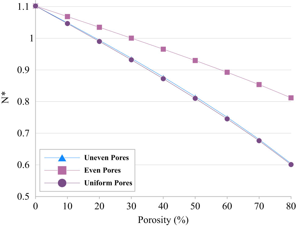
Effect of porosity variations on the dimensionless critical buckling load for different patterns of pores’ placement.
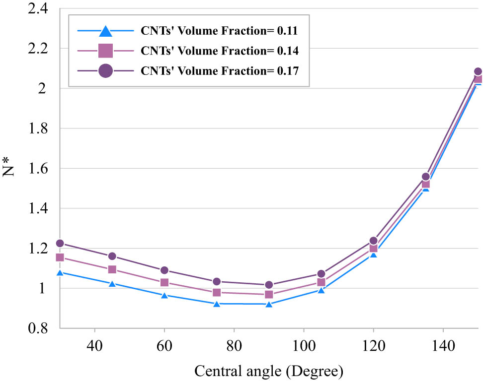
In Figure 4, in addition to reconsidering the porosity variations effect, the changes in the central opening angle are also taken into consideration. As it is clear, increasing this angle from 30 to 90 degrees has reduced the critical buckling load, but by enhancing it from 90 to 150 degrees, a sharp enhance in the critical buckling load is seen.
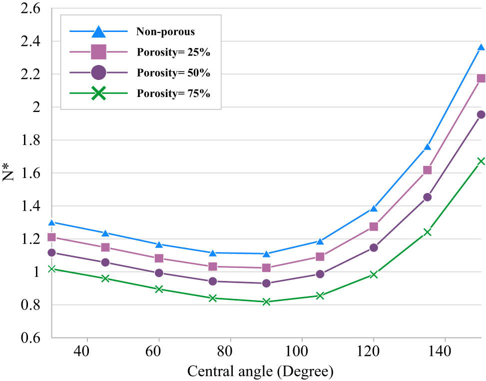
Effect of both porosity changes and the central angle increase on the dimensionless critical buckling load.
The reason for this effect backs to the geometrics of the structure that reduces or increases the stiffness of the whole structure. Different patterns of CNTs’ distribution are compared in Figure 5. As can be understood, there is no significant difference between their three types including O–O, U–U, and X–X, but the critical buckling load for the V–A pattern is the highest values, and that for A–V patterns are the lowest. It should be noted although it is stated that there is no significant difference between the mentioned three types; however, with more focus on the results it is seen that among these types, X–X and O–O have minimum and maximum values of the critical buckling loads. Figure 5 also shows the effect of another geometrical parameter of the structure, i.e., thickness to length. As can be expected, increasing this parameter resulted in enhancing the critical buckling load because the stiffness of the microbeam enhances.
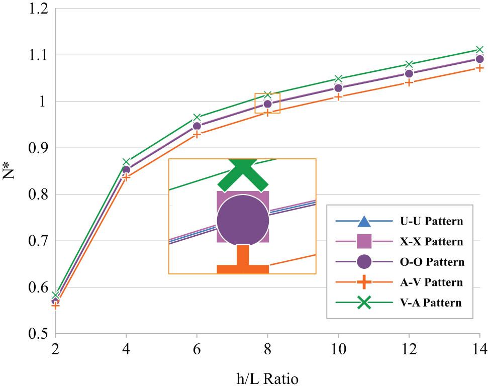
Influence of distribution patterns of CNTs across the skins’ thickness on the results.
Next, the influence of the volume fraction of CNTs on the buckling response of the curved microbeam is considered. Regardless of the nanotubes distribution patterns, it is seen in Figure 6 that by enhancing the amount of CNTs reinforcement within the matrix, due to their extreme stiffness, the stiffness of the whole skins and, in the following, the stiffness of the whole microbeam enhances, which means an increase in the critical buckling load.
Influence of the volume fraction of CNTs on the buckling behavior of the curved microbeam.
The effect of length-scale and temperature variations for two values of volume fraction (i.e., 0.11 and 0.17) of CNTs is illustrated in Figure 7a and b. An interesting outcome of this figure is that the influence of the length scale on the critical buckling load strongly depends on the temperature. As can be seen, at room temperature (i.e., at ΔT = 0), increasing the h c/μ m ratio leads the results to reduce but as the temperature increases, the structure behaves differently. It means increasing the h c/μ m results in enhancing the critical buckling load. It is true for both considered values for the volume fraction of CNTs. By comparing Figure 7a and b, it is found that the results of critical buckling load in Figure 7b, which relates to the CNTs’ volume fraction of 0.17, are more than 0.11 (i.e., Figure 7a).
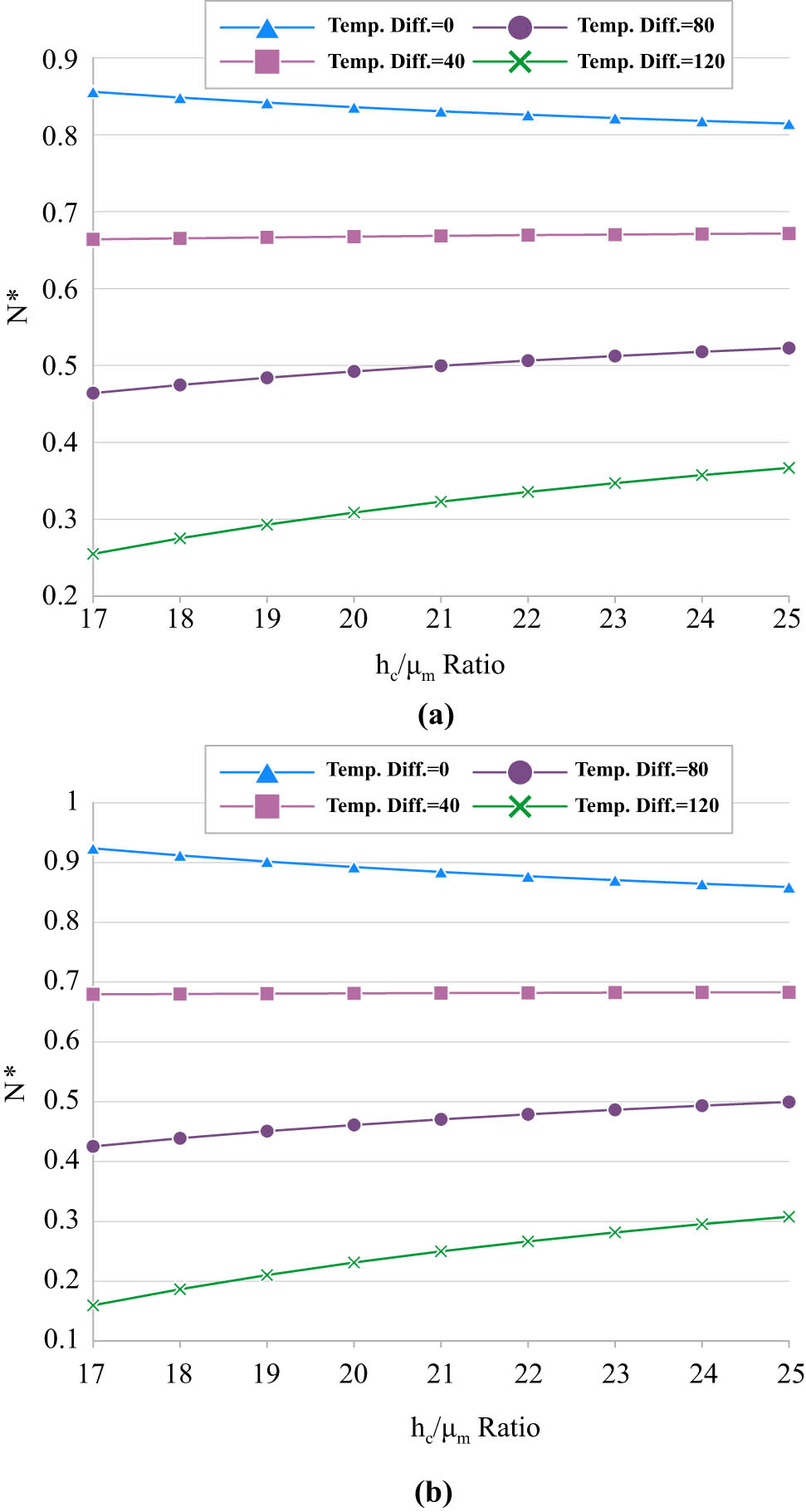
Effect of MCST length-scale parameter and temperature increase on the results for (a) CNTs’ volume fraction = 0.11 and (b) CNTs’ volume fraction = 0.17.
Figure 8a and b depicts the various effects of moisture on the critical buckling load. Based on these figures, increasing the moisture results in a softer structure, which means the critical buckling load is reduced. Also, it is seen, unlike the temperature, that at all values of moisture difference (i.e., ΔH) increasing the h c/μ m ratio results in the decrease of the buckling load. A similar finding with previous figures about the effect of volume fraction of CNTs is seen in these figures too.
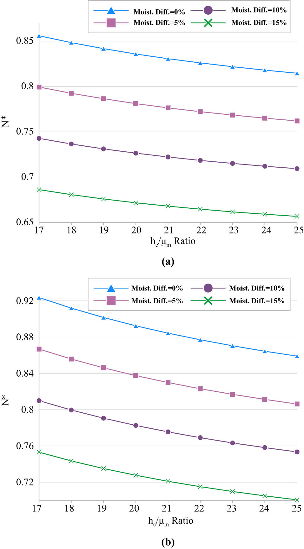
Effect of MCST length-scale parameter and increasing moisture values on the dimensionless critical buckling load for (a) CNTs’ volume fraction = 0.11 and (b) CNTs’ volume fraction = 0.17.
Tables 6 and 7 illustrate the effect of different parameters including thicknesses ratio, temperature, and moisture changes, as well as different pores’ placement patterns on the corresponding critical buckling load. These tables confirm the previous findings that stated that at higher temperature and moisture values, the critical buckling load decreases. Also, the conclusions about the effect of pores’ placement patterns on the results are confirmed again.
Effect of temperature variations based on thickness ratios for different patterns of pores placement
| Temperature difference (ΔT) | |||||
|---|---|---|---|---|---|
| 0 | 20 | 40 | 60 | 80 | |
| Pores placement pattern | |||||
| h c /h f = 10 | Even | ||||
| 1.0294 | 0.8439 | 0.6550 | 0.4624 | 0.2657 | |
| Uneven | |||||
| 0.9430 | 0.7575 | 0.5686 | 0.3760 | 0.1793 | |
| Uniform | |||||
| 0.9369 | 0.7521 | 0.5639 | 0.3719 | 0.1759 | |
| h c /h f = 15 | Even | ||||
| 0.9261 | 0.8033 | 0.6782 | 0.5505 | 0.4202 | |
| Uneven | |||||
| 0.8361 | 0.7134 | 0.5883 | 0.4606 | 0.3302 | |
| Uniform | |||||
| 0.8310 | 0.7088 | 0.5842 | 0.4572 | 0.3274 | |
Effect of moisture changes based on thickness ratios for different patterns of pores placement
| Moisture difference percentage (ΔH) | |||||
|---|---|---|---|---|---|
| 0 | 5 | 10 | 15 | 20 | |
| Pores placement pattern | |||||
| h c /h f = 10 | Even | ||||
| 1.0294 | 0.9633 | 0.8973 | 0.8312 | 0.7652 | |
| Uneven | |||||
| 0.9430 | 0.8770 | 0.8109 | 0.7449 | 0.6789 | |
| Uniform | |||||
| 0.9369 | 0.8719 | 0.8069 | 0.7419 | 0.6769 | |
| h c /h f = 15 | Even | ||||
| 0.9261 | 0.8676 | 0.8091 | 0.7506 | 0.6921 | |
| Uneven | |||||
| 0.8361 | 0.7777 | 0.7192 | 0.6607 | 0.6022 | |
| Uniform | |||||
| 0.8310 | 0.7734 | 0.7158 | 0.6582 | 0.6007 | |
Figure 9 compares three different cases, namely without foundation, just spring included foundation, and both springs and shear layer included foundation and investigates their effect on the critical buckling load of the under consideration model. As can be guessed, in the absence of the foundation, due to less structural rigidity, critical buckling load has the least value, but the addition of the foundation, either just springs or both springs and shear layer, results in increasing the critical buckling load. Since the presence of both springs and shear layer increases the rigidity of the foundation, therefore, its critical buckling load has more value too.
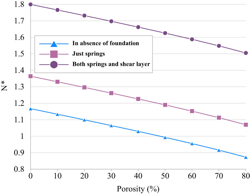
A comparison between different kinds of elastic foundations and their effect on the critical buckling load.
In Table 8, the exact values of dimensionless critical buckling load are listed for different values of the foundation’s moduli. As can be found, enhancing both moduli (either springs or shear layer) produces a structure that is more rigid and it leads to enhancement in the critical buckling load.
Effect of foundation’s moduli on the critical buckling load
| k p | k s | |||||
|---|---|---|---|---|---|---|
| 0 | 10 × 102 | 10 × 104 | 10 × 106 | 10 × 108 | 10 × 1010 | |
| 0 | 1.0292 | 1.0293 | 1.0294 | 1.0296 | 1.0313 | 1.2262 |
| 100 | 1.0298 | 1.0299 | 1.0300 | 1.0303 | 1.0318 | 1.2269 |
| 10 × 102 | 1.0335 | 1.0337 | 1.0338 | 1.0342 | 1.0357 | 1.2305 |
| 10 × 103 | 1.0729 | 1.0732 | 1.0735 | 1.0737 | 1.0749 | 1.2697 |
| 10 × 104 | 1.4648 | 1.4653 | 1.4657 | 1.4660 | 1.4668 | 1.6616 |
5 Conclusion
This presented study focused on considering the influence of the hygrothermal environment on the buckling behavior of a deeply curvy microbeam that is composed of three layers, namely an FGP core and two CNT-reinforced skins. Using MCST for accounting scale influence and RSDT in polar coordinates, which involves the thickness stretching effect and produces more accurate results, the governing differential equations are extracted. By ensuring the validity of the results, the effect of different parameters on the critical buckling load is investigated. Finally, some of the most prominent findings of this study are noted in the following. It is seen that the porosity percentage enhances, reduces the microbeam stiffness that leads to lower values of the critical buckling load. Also, the addition of CNTs to the matrix of the skins makes the skins and, accordingly, the whole structure stiffer, which means enhancing the critical buckling load. Among the three considered patterns of pores placement through the FGP core, the even pattern leads to the highest critical buckling loads. By comparing different types of distribution patterns of CNTs, it is seen that, respectively, V-A and A-V patterns lead to the highest and the lowest results of critical buckling load. Although increasing the central opening angle of the beam from 30 up to 90 degrees results in lower critical buckling load, but above 90 degrees, the critical buckling load tends to increase rapidly. Enhancing both temperature and moisture reduces the structure’s stiffness, which finally leads to decreasing the critical buckling load. Increasing h c/μ m as a criterion of length-scale parameter generally leads to the decrease of the critical buckling load. But at a higher temperature, it behaves differently. The addition of springs and shear layer to the foundation increases the structure’s rigidity, which causes increases in the critical buckling load. The author believes that considering such a structure in the polar coordinate, which results in more accurate results, can be utilized especially for deeply curved beams and the outcomes can be accounted as benchmarks for future works.
-
Funding information: The author states no funding involved.
-
Author contributions: The author has accepted responsibility for the entire content of this manuscript and approved its submission.
-
Conflict of interest: The author states no conflict of interest.
References
[1] Talebizadehsardari P, Eyvazian A, Azandariani MG, Tran TN, Rajak DK, Mahani RB. Buckling analysis of smart beams based on higher order shear deformation theory and numerical method. Steel Compos Struct. 2020;35:635–40. 10.12989/SCS.2020.35.5.635.Search in Google Scholar
[2] Yan X, Huang X, Chen Y, Liu Y, Xia L, Zhang T, et al. A theoretical strategy of pure carbon materials for lightweight and excellent absorption performance. Carbon NY. 2021;174:662–72. 10.1016/j.carbon.2020.11.044.Search in Google Scholar
[3] Yang Y, Chen H, Zou X, Shi X, Liu W, Feng L, et al. Flexible carbon-fiber/semimetal Bi nanosheet arrays as separable and recyclable plasmonic photocatalysts and photoelectrocatalysts. ACS Appl Mater Interfaces. 2020;12(22):24845–54. 10.1021/acsami.0c05695.Search in Google Scholar PubMed
[4] Kargar J, Arani AG, Arshid E, Rahaghi MI. Vibration analysis of spherical sandwich panels with MR fluids core and magneto-electro-elastic face sheets resting on orthotropic viscoelastic foundation. Struct Eng Mech. 2021;78:572. 10.12989/SEM.2021.78.5.557.Search in Google Scholar
[5] Arshid E, Khorshidvand AR, Khorsandijou SM. The effect of porosity on free vibration of SPFG circular plates resting on visco-Pasternak elastic foundation based on CPT, FSDT and TSDT. Struct Eng Mech. 2019;70:97–112. 10.12989/sem.2019.70.1.097.Search in Google Scholar
[6] Alhaifi K, Arshid E, Khorshidvand AR. Large deflection analysis of functionally graded saturated porous rectangular plates on nonlinear elastic foundation via GDQM. Steel Compos Struct. 2021;39:809. 10.12989/SCS.2021.39.6.795.Search in Google Scholar
[7] Li Y, Ren X, Zhao T, Xiao D, Liu K, Fang D. Dynamic response of stiffened plate under internal blast: experimental and numerical investigation. Mar Struct. 2021;77:102957.10.1016/j.marstruc.2021.102957Search in Google Scholar
[8] Zheng J, Zhang C, Li A. Experimental investigation on the mechanical properties of curved metallic plate dampers. Appl Sci. 2020;10(1):269.10.3390/app10010269Search in Google Scholar
[9] Zhang Z, Liu M, Zhou M, Chen J. Dynamic reliability analysis of nonlinear structures using a Duffing-system-based equivalent nonlinear system method. Int J Approx Reason. 2020;126:84–97. 10.1016/j.ijar.2020.08.006.Search in Google Scholar
[10] Gao N, Tang L, Deng J, Lu K, Hou H, Chen K. Design, fabrication and sound absorption test of composite porous metamaterial with embedding I-plates into porous polyurethane sponge. Appl Acoust. 2021;175:107845. 10.1016/j.apacoust.2020.107845.Search in Google Scholar
[11] Abedini M, Zhang C. Dynamic vulnerability assessment and damage prediction of RC columns subjected to severe impulsive loading. Struct Eng Mech. 2021;77:441–61.Search in Google Scholar
[12] Sun L, Yang Z, Jin Q, Yan W. Effect of axial compression ratio on seismic behavior of GFRP reinforced concrete columns. Int J Struct Stab Dyn. 2020;20(6):2040004.10.1142/S0219455420400040Search in Google Scholar
[13] Alam Z, Zhang C, Samali B. The role of viscoelastic damping on retrofitting seismic performance of asymmetric reinforced concrete structures. Earthq Eng Eng Vib. 2020;19(1):223–37.10.1007/s11803-020-0558-xSearch in Google Scholar
[14] Zhang C, Gholipour G, Mousavi A. Blast loads induced responses of RC structural members: state-of-the-art review. Compos Part B Eng. 2020;195:108066.10.1016/j.compositesb.2020.108066Search in Google Scholar
[15] Zhang C, Gholipour G, Mousavi A. Nonlinear dynamic behavior of simply-supported RC beams subjected to combined impact-blast loading. Eng Struct. 2019;181:124–42.10.1016/j.engstruct.2018.12.014Search in Google Scholar
[16] Hashim H, Salleh M, Omar M. Homogenous dispersion and interfacial bonding of carbon nanotube reinforced with aluminum matrix composite: a review. Rev Adv Mater Sci. 2019;58(1):295–303. 10.1515/rams-2019-0035.Search in Google Scholar
[17] Al-Khedher M, Pezeshki C, McHale J, Knorr F. Empirical modeling of nanoindentation of vertically aligned carbon nanotube turfs using intelligent systems. Fulle Nanotub Carbon Nanostruct. 2012;20(3):200–15. 10.1080/1536383X.2010.542590.Search in Google Scholar
[18] Al-Khedher M, Pezeshki C, McHale J, Knorr F. Quality classification via Raman identification and SEM analysis of carbon nanotube bundles using artificial neural networks. Nanotechnology. 2007;18(35):355703. 10.1088/0957-4484/18/35/355703.Search in Google Scholar
[19] Al-Khedher M, Pezeshki C, McHale J, Knorr F. Adaptive neuro-fuzzy modeling of mechanical behavior for vertically aligned carbon nanotube turfs. J Mater Sci Technol. 2011;27(4):301–8. 10.1016/S1005-0302(11)60066-2.Search in Google Scholar
[20] Iijima S. Helical microtubules of graphitic carbon. Nature. 1991;354(6348):56–8.10.1038/354056a0Search in Google Scholar
[21] Wattanasakulpong N, Chaikittiratana A. Exact solutions for static and dynamic analyses of carbon nanotube-reinforced composite plates with Pasternak elastic foundation. Appl Math Model. 2015;39(18):5459–72. 10.1016/j.apm.2014.12.058.Search in Google Scholar
[22] Zhang L, Liew K, Reddy J. Postbuckling analysis of bi-axially compressed laminated nanocomposite plates using the first-order shear deformation theory. Composite Struct. 2016;152:418–31. 10.1016/j.compstruct.2016.05.040.Search in Google Scholar
[23] Talebizadehsardari P, Eyvazian A, Asmael M, Karami B, Shahsavari D, Mahani R. Static bending analysis of functionally graded polymer composite curved beams reinforced with carbon nanotubes. Thin-Walled Struct. 2020;157:107139. 10.1016/j.tws.2020.107139.Search in Google Scholar
[24] Arshid E, Khorasani M, Soleimani-Javid Z, Amir S, Tounsi A. Porosity-dependent vibration analysis of FG microplates embedded by polymeric nanocomposite patches considering hygrothermal effect via an innovative plate theory. Eng Comput. 2021;1–22. 10.1007/s00366-021-01382-y.Search in Google Scholar
[25] Karami B, Shahsavari D, Janghorban M, Li L. Elastic guided waves in fully-clamped functionally graded carbon nanotube-reinforced composite plates. Mater Res Express. 2019;6(9):0950a9. 10.1088/2053-1591/ab3474.Search in Google Scholar
[26] Chakraborty S, Dey T, Kumar R. Stability and vibration analysis of CNT-Reinforced functionally graded laminated composite cylindrical shell panels using semi-analytical approach. Compos Part B Eng. 2019;168:1–14. 10.1016/j.compositesb.2018.12.051.Search in Google Scholar
[27] Arshid E, Amir S, Loghman A. Bending and buckling behaviors of heterogeneous temperature-dependent micro annular/circular porous sandwich plates integrated by FGPEM nano-Composite layers. J Sandw Struct Mater. 2020;109963622095502. 10.1177/1099636220955027.Search in Google Scholar
[28] Eyvazian A, Hamouda AM, Tarlochan F, Mohsenizadeh S, Dastjerdi AA. Damping and vibration response of viscoelastic smart sandwich plate reinforced with non-uniform Graphene platelet with magnetorheological fluid core. Steel Compos Struct. 2019;33:891–906. 10.12989/scs.2019.33.6.891.Search in Google Scholar
[29] Akbarzadeh A, Arian Nik M, Pasini D. Vibration responses and suppression of variable stiffness laminates with optimally steered fibers and magnetostrictive layers. Compos Part B Eng. 2016;91:315–26. 10.1016/j.compositesb.2016.02.003.Search in Google Scholar
[30] Ramamoorthy M, Rajamohan V, AK J. Vibration analysis of a partially treated laminated composite magnetorheological fluid sandwich plate. J Vib Control. 2016;22(3):869–95. 10.1177/1077546314532302.Search in Google Scholar
[31] Liu H, Lv Z, Wu H. Nonlinear free vibration of geometrically imperfect functionally graded sandwich nanobeams based on nonlocal strain gradient theory. Composite Struct. 2019;214:47–61. 10.1016/j.compstruct.2019.01.090.Search in Google Scholar
[32] Amir S, Arshid E, Khoddami Maraghi Z, Loghman A, Ghorbanpour Arani A. Vibration analysis of magnetorheological fluid circular sandwich plates with magnetostrictive facesheets exposed to monotonic magnetic field located on visco-Pasternak substrate. J Vib Control. 2020;26(17–18):1523–37. 10.1177/1077546319899203.Search in Google Scholar
[33] Khorasani M, Soleimani-Javid Z, Arshid E, Lampani L, Civalek Ö. Thermo-elastic buckling of honeycomb micro plates integrated with FG-GNPs reinforced Epoxy skins with stretching effect. Composite Struct. 2020;258:113430. 10.1016/j.compstruct.2020.113430.Search in Google Scholar
[34] Eyvazian A, Shahsavari D, Karami B. On the dynamic of graphene reinforced nanocomposite cylindrical shells subjected to a moving harmonic load. Int J Eng Sci. 2020;154:103339. 10.1016/j.ijengsci.2020.103339.Search in Google Scholar
[35] Mahani R, Eyvazian A, Musharavati F, Sebaey T, Talebizadehsardari P. Thermal buckling of laminated Nano-Composite conical shell reinforced with graphene platelets. Thin-Walled Struct. 2020;155:106913. 10.1016/j.tws.2020.106913.Search in Google Scholar
[36] Eyvazian A, Musharavati F, Tarlochan F, Pasharavesh A, Rajak DK, Husain MB, et al. Free vibration of FG-GPLRC conical panel on elastic foundation. Struct Eng Mech. 2020;75:1–18. 10.12989/SEM.2020.75.1.001.Search in Google Scholar
[37] Zhu P, Lei Z, Liew K. Static and free vibration analyses of carbon nanotube-reinforced composite plates using finite element method with first order shear deformation plate theory. Composite Struct. 2012;94(4):1450–60. 10.1016/j.compstruct.2011.11.010.Search in Google Scholar
[38] Arshid E, Khorshidvand A. Free vibration analysis of saturated porous FG circular plates integrated with piezoelectric actuators via differential quadrature method. Thin-Walled Struct. 2018;125:220–33. 10.1016/j.tws.2018.01.007.Search in Google Scholar
[39] Loghman A, Cheraghbak A. Agglomeration effects on electro-magneto-thermo elastic behavior of nano-composite piezoelectric cylinder. Polym Compos. 2018;39(5):1594–1603. 10.1002/pc.24104.Search in Google Scholar
[40] Mirzaei M, Kiani Y. Free vibration of functionally graded carbon nanotube reinforced composite cylindrical panels. Composite Struct. 2016;142:45–56. 10.1016/J.COMPSTRUCT.2015.12.071.Search in Google Scholar
[41] Thu P, Duc N. Non-linear dynamic response and vibration of an imperfect three-phase laminated nanocomposite cylindrical panel resting on elastic foundations in thermal environments. Sci Eng Composite Mater. 2016;24(6):951–62.10.1515/secm-2015-0467Search in Google Scholar
[42] Selim B, Zhang L, Liew K. Vibration analysis of CNT reinforced functionally graded composite plates in a thermal environment based on Reddy’s higher-order shear deformation theory. Composite Struct. 2016;156:276–90. 10.1016/j.compstruct.2015.10.026.Search in Google Scholar
[43] Nguyen D. Nonlinear thermo- electro-mechanical dynamic response of shear deformable piezoelectric sigmoid functionally graded sandwich circular cylindrical shells on elastic foundations. J Sandw Struct Mater. 2018;20(3):351–78. 10.1177/1099636216653266.Search in Google Scholar
[44] Mehar K, Panda S, Bui T, Mahapatra T. Nonlinear thermoelastic frequency analysis of functionally graded CNT-reinforced single/doubly curved shallow shell panels by FEM. J Therm Stresses. 2017;40(7):899–916. 10.1080/01495739.2017.1318689.Search in Google Scholar
[45] Yas M, Samadi N. Free vibrations and buckling analysis of carbon nanotube-reinforced composite Timoshenko beams on elastic foundation. Int J Press Vessel Pip. 2012;98:119–28. 10.1016/J.IJPVP.2012.07.012.Search in Google Scholar
[46] Zhao X, Chen B, Li Y, Zhu W, Nkiegaing F, Shao Y. Forced vibration analysis of Timoshenko double-beam system under compressive axial load by means of Green’s functions. J Sound Vib. 2020;464:115001.10.1016/j.jsv.2019.115001Search in Google Scholar
[47] Zhao X, Zhu W, Li Y. Analytical solutions of nonlocal coupled thermoelastic forced vibrations of micro-/nano-beams by means of Green’s functions. J Sound Vib. 2020;481:115407.10.1016/j.jsv.2020.115407Search in Google Scholar
[48] Soleimani-Javid Z, Arshid E, Khorasani M, Amir S, Tounsi A. Size-dependent flexoelectricity-based vibration characteristics of honeycomb sandwich plates with various boundary conditions. Adv Nano Res. 2021;10:460. 10.12989/ANR.2021.10.5.449.Search in Google Scholar
[49] Wang X, Handschuh‐Wang S, Xu Y, Xiang L, Zhou Z, Wang T, et al. Hierarchical micro/nanostructured diamond gradient surface for controlled water transport and fog collection. Adv Mater Interfaces. 2021;2100196. 10.1002/admi.202100196.Search in Google Scholar
[50] Cao X, Huang Z, He C, Wu W, Xi L, Li Y, et al. In-situ synchrotron X-ray tomography investigation of the imperfect smooth-shell cylinder structure. Composite Struct. 2021;267:113926. 10.1016/j.compstruct.2021.113926.Search in Google Scholar
[51] Khorasani M, Eyvazian A, Karbon M, Tounsi A, Lampani L, Sebaey TA. Magneto-electro-elastic vibration analysis of modified couple stress-based three-layered micro rectangular plates exposed to multi-physical fields considering the flexoelectricity effects. Smart Struct Syst. 2020;26:331–43. 10.12989/sss.2020.26.3.331.Search in Google Scholar
[52] Amir S, Arshid E, Arani MR. Size-dependent magneto-electro-elastic vibration analysis of FG saturated porous annular/circular micro sandwich plates embedded with nano-composite face sheets subjected to multi-physical pre loads. Smart Struct Syst. 2019;23:429–47. 10.12989/sss.2019.23.5.429.Search in Google Scholar
[53] Arshid E, Amir S, Loghman A. Static and dynamic analyses of FG-GNPs reinforced porous nanocomposite annular micro-plates based on MSGT. Int J Mech Sci. 2020;180:105656. 10.1016/j.ijmecsci.2020.105656.Search in Google Scholar
[54] Hosseini M, Gorgani H, Shishesaz M, Hadi A. Size-dependent stress analysis of single-wall carbon nanotube based on strain gradient theory. Int J Appl Mech. 2017;09(06):1750087. 10.1142/S1758825117500879.Search in Google Scholar
[55] Malikan M, Nguyen V. Buckling analysis of piezo-magnetoelectric nanoplates in hygrothermal environment based on a novel one variable plate theory combining with higher-order nonlocal strain gradient theory. Phys E Low-Dimens Syst Nanostruct. 2018;102:8–28. 10.1016/j.physe.2018.04.018.Search in Google Scholar
[56] Imani Aria A, Biglari H. Computational vibration and buckling analysis of microtubule bundles based on nonlocal strain gradient theory. Appl Math Comput. 2018;321:313–32. 10.1016/j.amc.2017.10.050.Search in Google Scholar
[57] Arshid E, Arshid H, Amir S, Mousavi S. Free vibration and buckling analyses of FG porous sandwich curved microbeams in thermal environment under magnetic field based on modified couple stress theory. Arch Civ Mech Eng. 2021;21(1):1–23. 10.1007/s43452-020-00150-x.Search in Google Scholar
[58] Jouneghani F, Babamoradi H, Dimitri R, Tornabene F. A modified couple stress elasticity for non-uniform composite laminated beams based on the Ritz formulation. Molecules. 2020;25(6):1404. 10.3390/molecules25061404.Search in Google Scholar PubMed PubMed Central
[59] Kiarasi F, Babaei M, Dimitri R, Tornabene F. Hygrothermal modeling of the buckling behavior of sandwich plates with nanocomposite face sheets resting on a Pasternak foundation. Contin Mech Thermodyn. 2020;33(4):911–32. 10.1007/s00161-020-00929-6.Search in Google Scholar
[60] Soltani M, Atoufi F, Mohri F, Dimitri R, Tornabene F. Nonlocal elasticity theory for lateral stability analysis of tapered thin-walled nanobeams with axially varying materials. Thin-Walled Struct. 2021;159:107268. 10.1016/j.tws.2020.107268.Search in Google Scholar
[61] Karami B, Janghorban M, Shahsavari D, Dimitri R, Tornabene F. Nonlocal buckling analysis of composite curved beams reinforced with functionally graded carbon nanotubes. Molecules. 2019;24(15):2750. 10.3390/molecules24152750.Search in Google Scholar PubMed PubMed Central
[62] Arefi M, Bidgoli E, Dimitri R, Tornabene F, Reddy J. Size-dependent free vibrations of FG polymer composite curved nanobeams reinforced with graphene nanoplatelets resting on pasternak foundations. Appl Sci. 2019;9(8):1580. 10.3390/app9081580.Search in Google Scholar
[63] Sobhy M. Buckling and vibration of FG graphene platelets/aluminum sandwich curved nanobeams considering the thickness stretching effect and exposed to a magnetic field. Results Phys. 2020;16:102865. 10.1016/j.rinp.2019.102865.Search in Google Scholar
[64] Talebizadehsardari P, Eyvazian A, Musharavati F, Mahani R, Sebaey T. Elastic wave characteristics of graphene reinforced polymer nanocomposite curved beams including thickness stretching effect. Polymers. 2020;12(10):2194. 10.3390/polym12102194.Search in Google Scholar PubMed PubMed Central
[65] Arshid E, Amir S. Size-dependent vibration analysis of fluid-infiltrated porous curved microbeams integrated with reinforced functionally graded graphene platelets face sheets considering thickness stretching effect. Proc Inst Mech Engineers Part L J Mater Des Appl. 2021;235(5):1077–99. 10.1177/1464420720985556.Search in Google Scholar
[66] Amir S, Arshid E, Rasti-Alhosseini S, Loghman A. Quasi-3D tangential shear deformation theory for size-dependent free vibration analysis of three-layered FG porous micro rectangular plate integrated by nano-composite faces in hygrothermal environment. J Therm Stresses. 2019;43(2):133–56. 10.1080/01495739.2019.1660601.Search in Google Scholar
[67] Amir S, Soleimani‐Javid Z, Arshid E. Size‐dependent free vibration of sandwich micro beam with porous core subjected to thermal load based on SSDBT. J Appl Math Mech/Z Angew Math Mech. 2019;99(9):e201800334. 10.1002/zamm.201800334.Search in Google Scholar
[68] Barati M, Sadr M, Zenkour A. Buckling analysis of higher order graded smart piezoelectric plates with porosities resting on elastic foundation. Int J Mech Sci. 2016;117:309–20. 10.1016/J.IJMECSCI.2016.09.012.Search in Google Scholar
[69] Sharifan M, Jabbari M. Mechanical buckling analysis of saturated porous functionally graded elliptical plates subjected to in-plane force resting on two parameters elastic foundation based on HSDT. J Press Vessel Technol. 2020;142(4):041302. 10.1115/1.4046707.Search in Google Scholar PubMed PubMed Central
[70] Soleimani-Javid Z, Arshid E, Amir S, Bodaghi M. On the higher-order thermal vibrations of FG saturated porous cylindrical micro-shells integrated with nanocomposite skins in viscoelastic medium. Def Technol. 2021. 10.1016/J.DT.2021.07.007.Search in Google Scholar
[71] Thanh C, Tran L, Vu-Huu T, Nguyen-Xuan H, Abdel-Wahab M. Size-dependent nonlinear analysis and damping responses of FG-CNTRC micro-plates. Comput Methods Appl Mech Eng. 2019;353:253–76. 10.1016/j.cma.2019.05.002.Search in Google Scholar
[72] Arshid E, Amir S, Loghman A. Thermal buckling analysis of FG graphene nanoplatelets reinforced porous nanocomposite MCST-based annular/circular microplates. Aerosp Sci Technol. 2021;111:106561. 10.1016/j.ast.2021.106561.Search in Google Scholar
[73] Khorasani M, Soleimani-Javid Z, Arshid E, Amir S, Civalek Ö. Vibration analysis of graphene nanoplatelets’ reinforced composite plates integrated by piezo-electromagnetic patches on the piezo-electromagnetic media. Waves Random Complex Media. 2021;1–31. 10.1080/17455030.2021.1956017.Search in Google Scholar
[74] Natarajan S, Haboussi M, Manickam G. Application of higher-order structural theory to bending and free vibration analysis of sandwich plates with CNT reinforced composite facesheets. Composite Struct. 2014;113:197–207. 10.1016/j.compstruct.2014.03.007.Search in Google Scholar
[75] Mehar K, Kumar Panda S. Thermal free vibration behavior of FG-CNT reinforced sandwich curved panel using finite element method. Polym Compos. 2017;39(8):2751–64.10.1002/pc.24266Search in Google Scholar
[76] Jooybar N, Malekzadeh P, Fiouz A. Vibration of functionally graded carbon nanotubes reinforced composite truncated conical panels with elastically restrained against rotation edges in thermal environment. Compos Part B: Eng. 2016;106:242–61. 10.1016/j.compositesb.2016.09.030.Search in Google Scholar
[77] Mohammadimehr M, Arshid E, Alhosseini SMAR, Amir S, Arani MRG. Free vibration analysis of thick cylindrical MEE composite shells reinforced CNTs with temperature-dependent properties resting on viscoelastic foundation. Struct Eng Mech. 2019;70:683–702. 10.12989/sem.2019.70.6.683.Search in Google Scholar
[78] Ansari R, Shojaei M, Mohammadi V, Gholami R, Rouhi H. Size-dependent thermal buckling and postbuckling of functionally graded annular microplates based on the modified strain gradient theory. J Therm Stresses. 2014;37(2):174–201. 10.1080/01495739.2013.839767.Search in Google Scholar
[79] Ma Y, Gao Y, Yang W, He D. Free vibration of a micro-scale composite laminated Reddy plate using a finite element method based on the new modified couple stress theory. Results Phys. 2020;16:102903. 10.1016/j.rinp.2019.102903.Search in Google Scholar
[80] Amir S, Arshid E, Maraghi ZK. Free vibration analysis of magneto-rheological smart annular three-layered plates subjected to magnetic field in viscoelastic medium. Smart Struct Syst. 2020;25:581–92. 10.12989/sss.2020.25.5.581.Search in Google Scholar
[81] Polit O, Anant C, Anirudh B, Ganapathi M. Functionally graded graphene reinforced porous nanocomposite curved beams: bending and elastic stability using a higher-order model with thickness stretch effect. Compos Part B Eng. 2019;166:310–27. 10.1016/j.compositesb.2018.11.074.Search in Google Scholar
[82] Arshid E, Kiani A, Amir S, Zarghami Dehaghani M. Asymmetric free vibration analysis of first-order shear deformable functionally graded magneto-electro-thermo-elastic circular plates. Proc Inst Mech Eng Part C J Mech Eng Sci. 2019;233(16):5659–75. 10.1177/0954406219850598.Search in Google Scholar
[83] Arshid E, Kiani A, Amir S. Magneto-electro-elastic vibration of moderately thick FG annular plates subjected to multi physical loads in thermal environment using GDQ method by considering neutral surface. Proc Inst Mech Eng Part L J Mater Des Appl. 2019;233(10):2140–59. 10.1177/1464420719832626.Search in Google Scholar
[84] Tadi Beni Y, Mehralian F, Zeighampour H. The modified couple stress functionally graded cylindrical thin shell formulation. Mech Adv Mater Struct. 2016;23(7):791–801. 10.1080/15376494.2015.1029167.Search in Google Scholar
[85] Amir S, Bidgoli E, Arshid E. Size-dependent vibration analysis of a three-layered porous rectangular nano plate with piezo-electromagnetic face sheets subjected to pre loads based on SSDT. Mech Adv Mater Struct. 2020;27(8):605–19. 10.1080/15376494.2018.1487612.Search in Google Scholar
[86] Reddy J. Nonlocal theories for bending, buckling and vibration of beams. Int J Eng Sci. 2007;45(2–8):288–307. 10.1016/j.ijengsci.2007.04.004.Search in Google Scholar
[87] Aydogdu M. A general nonlocal beam theory: its application to nanobeam bending, buckling and vibration. Phys E Low-Dimens Syst Nanostruct. 2009;41(9):1651–5. 10.1016/j.physe.2009.05.014.Search in Google Scholar
[88] Eltaher M, Emam S, Mahmoud F. Static and stability analysis of nonlocal functionally graded nanobeams. Composite Struct. 2013;96:82–8. 10.1016/j.compstruct.2012.09.030.Search in Google Scholar
[89] Mallek H, Jrad H, Wali M, Dammak F. Nonlinear dynamic analysis of piezoelectric-bonded FG-CNTR composite structures using an improved FSDT theory. Eng Comput. 2019;37(2):1389–1407. 10.1007/s00366-019-00891-1.Search in Google Scholar
[90] Mousavi SB, Amir S, Jafari A, Arshid E. Analytical solution for analyzing initial curvature effect on vibrational behavior of PM beams integrated with FGP layers based on trigonometric theories. Adv Nano Res. 2021;10(3):235–51. 10.12989/ANR.2021.10.3.235.Search in Google Scholar
© 2021 Mohammad Alkhedher, published by De Gruyter
This work is licensed under the Creative Commons Attribution 4.0 International License.
Articles in the same Issue
- Research Articles
- Improved impedance matching by multi-componential metal-hybridized rGO toward high performance of microwave absorption
- Pure-silk fibroin hydrogel with stable aligned micropattern toward peripheral nerve regeneration
- Effective ion pathways and 3D conductive carbon networks in bentonite host enable stable and high-rate lithium–sulfur batteries
- Fabrication and characterization of 3D-printed gellan gum/starch composite scaffold for Schwann cells growth
- Synergistic strengthening mechanism of copper matrix composite reinforced with nano-Al2O3 particles and micro-SiC whiskers
- Deformation mechanisms and plasticity of ultrafine-grained Al under complex stress state revealed by digital image correlation technique
- On the deformation-induced grain rotations in gradient nano-grained copper based on molecular dynamics simulations
- Removal of sulfate from aqueous solution using Mg–Al nano-layered double hydroxides synthesized under different dual solvent systems
- Microwave-assisted sol–gel synthesis of TiO2-mixed metal oxide nanocatalyst for degradation of organic pollutant
- Electrophoretic deposition of graphene on basalt fiber for composite applications
- Polyphenylene sulfide-coated wrench composites by nanopinning effect
- Thermal conductivity and thermoelectric properties in 3D macroscopic pure carbon nanotube materials
- An effective thermal conductivity and thermomechanical homogenization scheme for a multiscale Nb3Sn filaments
- Friction stir spot welding of AA5052 with additional carbon fiber-reinforced polymer composite interlayer
- Improvement of long-term cycling performance of high-nickel cathode materials by ZnO coating
- Quantum effects of gas flow in nanochannels
- An approach to effectively improve the interfacial bonding of nano-perfused composites by in situ growth of CNTs
- Effects of nano-modified polymer cement-based materials on the bending behavior of repaired concrete beams
- Effects of the combined usage of nanomaterials and steel fibres on the workability, compressive strength, and microstructure of ultra-high performance concrete
- One-pot solvothermal synthesis and characterization of highly stable nickel nanoparticles
- Comparative study on mechanisms for improving mechanical properties and microstructure of cement paste modified by different types of nanomaterials
- Effect of in situ graphene-doped nano-CeO2 on microstructure and electrical contact properties of Cu30Cr10W contacts
- The experimental study of CFRP interlayer of dissimilar joint AA7075-T651/Ti-6Al-4V alloys by friction stir spot welding on mechanical and microstructural properties
- Vibration analysis of a sandwich cylindrical shell in hygrothermal environment
- Water barrier and mechanical properties of sugar palm crystalline nanocellulose reinforced thermoplastic sugar palm starch (TPS)/poly(lactic acid) (PLA) blend bionanocomposites
- Strong quadratic acousto-optic coupling in 1D multilayer phoxonic crystal cavity
- Three-dimensional shape analysis of peripapillary retinal pigment epithelium-basement membrane layer based on OCT radial images
- Solvent regulation synthesis of single-component white emission carbon quantum dots for white light-emitting diodes
- Xanthate-modified nanoTiO2 as a novel vulcanization accelerator enhancing mechanical and antibacterial properties of natural rubber
- Effect of steel fiber on impact resistance and durability of concrete containing nano-SiO2
- Ultrasound-enhanced biosynthesis of uniform ZnO nanorice using Swietenia macrophylla seed extract and its in vitro anticancer activity
- Temperature dependence of hardness prediction for high-temperature structural ceramics and their composites
- Study on the frequency of acoustic emission signal during crystal growth of salicylic acid
- Controllable modification of helical carbon nanotubes for high-performance microwave absorption
- Role of dry ozonization of basalt fibers on interfacial properties and fracture toughness of epoxy matrix composites
- Nanosystem’s density functional theory study of the chlorine adsorption on the Fe(100) surface
- A rapid nanobiosensing platform based on herceptin-conjugated graphene for ultrasensitive detection of circulating tumor cells in early breast cancer
- Improving flexural strength of UHPC with sustainably synthesized graphene oxide
- The role of graphene/graphene oxide in cement hydration
- Structural characterization of microcrystalline and nanocrystalline cellulose from Ananas comosus L. leaves: Cytocompatibility and molecular docking studies
- Evaluation of the nanostructure of calcium silicate hydrate based on atomic force microscopy-infrared spectroscopy experiments
- Combined effects of nano-silica and silica fume on the mechanical behavior of recycled aggregate concrete
- Safety study of malapposition of the bio-corrodible nitrided iron stent in vivo
- Triethanolamine interface modification of crystallized ZnO nanospheres enabling fast photocatalytic hazard-free treatment of Cr(vi) ions
- Novel electrodes for precise and accurate droplet dispensing and splitting in digital microfluidics
- Construction of Chi(Zn/BMP2)/HA composite coating on AZ31B magnesium alloy surface to improve the corrosion resistance and biocompatibility
- Experimental and multiscale numerical investigations on low-velocity impact responses of syntactic foam composites reinforced with modified MWCNTs
- Comprehensive performance analysis and optimal design of smart light pole for cooperative vehicle infrastructure system
- Room temperature growth of ZnO with highly active exposed facets for photocatalytic application
- Influences of poling temperature and elongation ratio on PVDF-HFP piezoelectric films
- Large strain hardening of magnesium containing in situ nanoparticles
- Super stable water-based magnetic fluid as a dual-mode contrast agent
- Photocatalytic activity of biogenic zinc oxide nanoparticles: In vitro antimicrobial, biocompatibility, and molecular docking studies
- Hygrothermal environment effect on the critical buckling load of FGP microbeams with initial curvature integrated by CNT-reinforced skins considering the influence of thickness stretching
- Thermal aging behavior characteristics of asphalt binder modified by nano-stabilizer based on DSR and AFM
- Building effective core/shell polymer nanoparticles for epoxy composite toughening based on Hansen solubility parameters
- Structural characterization and nanoscale strain field analysis of α/β interface layer of a near α titanium alloy
- Optimization of thermal and hydrophobic properties of GO-doped epoxy nanocomposite coatings
- The properties of nano-CaCO3/nano-ZnO/SBR composite-modified asphalt
- Three-dimensional metallic carbon allotropes with superhardness
- Physical stability and rheological behavior of Pickering emulsions stabilized by protein–polysaccharide hybrid nanoconjugates
- Optimization of volume fraction and microstructure evolution during thermal deformation of nano-SiCp/Al–7Si composites
- Phase analysis and corrosion behavior of brazing Cu/Al dissimilar metal joint with BAl88Si filler metal
- High-efficiency nano polishing of steel materials
- On the rheological properties of multi-walled carbon nano-polyvinylpyrrolidone/silicon-based shear thickening fluid
- Fabrication of Ag/ZnO hollow nanospheres and cubic TiO2/ZnO heterojunction photocatalysts for RhB degradation
- Fabrication and properties of PLA/nano-HA composite scaffolds with balanced mechanical properties and biological functions for bone tissue engineering application
- Investigation of the early-age performance and microstructure of nano-C–S–H blended cement-based materials
- Reduced graphene oxide coating on basalt fabric using electrophoretic deposition and its role in the mechanical and tribological performance of epoxy/basalt fiber composites
- Effect of nano-silica as cementitious materials-reducing admixtures on the workability, mechanical properties and durability of concrete
- Machine-learning-assisted microstructure–property linkages of carbon nanotube-reinforced aluminum matrix nanocomposites produced by laser powder bed fusion
- Physical, thermal, and mechanical properties of highly porous polylactic acid/cellulose nanofibre scaffolds prepared by salt leaching technique
- A comparative study on characterizations and synthesis of pure lead sulfide (PbS) and Ag-doped PbS for photovoltaic applications
- Clean preparation of washable antibacterial polyester fibers by high temperature and high pressure hydrothermal self-assembly
- Al 5251-based hybrid nanocomposite by FSP reinforced with graphene nanoplates and boron nitride nanoparticles: Microstructure, wear, and mechanical characterization
- Interlaminar fracture toughness properties of hybrid glass fiber-reinforced composite interlayered with carbon nanotube using electrospray deposition
- Microstructure and life prediction model of steel slag concrete under freezing-thawing environment
- Synthesis of biogenic silver nanoparticles from the seed coat waste of pistachio (Pistacia vera) and their effect on the growth of eggplant
- Study on adaptability of rheological index of nano-PUA-modified asphalt based on geometric parameters of parallel plate
- Preparation and adsorption properties of nano-graphene oxide/tourmaline composites
- A study on interfacial behaviors of epoxy/graphene oxide derived from pitch-based graphite fibers
- Multiresponsive carboxylated graphene oxide-grafted aptamer as a multifunctional nanocarrier for targeted delivery of chemotherapeutics and bioactive compounds in cancer therapy
- Piezoresistive/piezoelectric intrinsic sensing properties of carbon nanotube cement-based smart composite and its electromechanical sensing mechanisms: A review
- Smart stimuli-responsive biofunctionalized niosomal nanocarriers for programmed release of bioactive compounds into cancer cells in vitro and in vivo
- Photoremediation of methylene blue by biosynthesized ZnO/Fe3O4 nanocomposites using Callistemon viminalis leaves aqueous extract: A comparative study
- Study of gold nanoparticles’ preparation through ultrasonic spray pyrolysis and lyophilisation for possible use as markers in LFIA tests
- Review Articles
- Advance on the dispersion treatment of graphene oxide and the graphene oxide modified cement-based materials
- Development of ionic liquid-based electroactive polymer composites using nanotechnology
- Nanostructured multifunctional electrocatalysts for efficient energy conversion systems: Recent perspectives
- Recent advances on the fabrication methods of nanocomposite yarn-based strain sensor
- Review on nanocomposites based on aerospace applications
- Overview of nanocellulose as additives in paper processing and paper products
- The frontiers of functionalized graphene-based nanocomposites as chemical sensors
- Material advancement in tissue-engineered nerve conduit
- Carbon nanostructure-based superhydrophobic surfaces and coatings
- Functionalized graphene-based nanocomposites for smart optoelectronic applications
- Interfacial technology for enhancement in steel fiber reinforced cementitious composite from nano to macroscale
- Metal nanoparticles and biomaterials: The multipronged approach for potential diabetic wound therapy
- Review on resistive switching mechanisms of bio-organic thin film for non-volatile memory application
- Nanotechnology-enabled biomedical engineering: Current trends, future scopes, and perspectives
- Research progress on key problems of nanomaterials-modified geopolymer concrete
- Smart stimuli-responsive nanocarriers for the cancer therapy – nanomedicine
- An overview of methods for production and detection of silver nanoparticles, with emphasis on their fate and toxicological effects on human, soil, and aquatic environment
- Effects of chemical modification and nanotechnology on wood properties
- Mechanisms, influencing factors, and applications of electrohydrodynamic jet printing
- Application of antiviral materials in textiles: A review
- Phase transformation and strengthening mechanisms of nanostructured high-entropy alloys
- Research progress on individual effect of graphene oxide in cement-based materials and its synergistic effect with other nanomaterials
- Catalytic defense against fungal pathogens using nanozymes
- A mini-review of three-dimensional network topological structure nanocomposites: Preparation and mechanical properties
- Mechanical properties and structural health monitoring performance of carbon nanotube-modified FRP composites: A review
- Nano-scale delivery: A comprehensive review of nano-structured devices, preparative techniques, site-specificity designs, biomedical applications, commercial products, and references to safety, cellular uptake, and organ toxicity
- Effects of alloying, heat treatment and nanoreinforcement on mechanical properties and damping performances of Cu–Al-based alloys: A review
- Recent progress in the synthesis and applications of vertically aligned carbon nanotube materials
- Thermal conductivity and dynamic viscosity of mono and hybrid organic- and synthetic-based nanofluids: A critical review
- Recent advances in waste-recycled nanomaterials for biomedical applications: Waste-to-wealth
- Layup sequence and interfacial bonding of additively manufactured polymeric composite: A brief review
- Quantum dots synthetization and future prospect applications
- Approved and marketed nanoparticles for disease targeting and applications in COVID-19
- Strategies for improving rechargeable lithium-ion batteries: From active materials to CO2 emissions