Mathematical Modelling Comparison of a Reciprocating, a Szorenyi Rotary, and a Wankel Rotary Engine
-
Luis F. Espinosa
 and
Petros Lappas
and
Petros Lappas

Abstract
This paper provides an explanation of the geometry, design, and operational principles for the three engines; having special emphasis in the Szorenyi rotary engine which has a deforming rhombus revolving inside a mathematically defined stator. A basic ideal mathematical simulation of those engines were performed, assuming the Otto cycle for the three engines. Also, it assumes the volumetric efficiency of 100%, a wide-open throttle (WOT), no knock nor any mechanical or thermal losses. This simulation focuses on how the fuel burns during combustion, creating pressure and thus, net work. A comparison in pressure traces and cycle performance is made. The study concludes analysing and comparing the ignition advance; finding the best advance for each engine thus the net work between the three engines during one working cycle. Finally, this paper analyses how the different volume change ratio for the combustion chamber of the Szorenyi, Wankel and the reciprocating engine have an effect in the pressure, net work and thermal efficiency generated inside the chamber during combustion for every working cycle.
1 Introduction
Rotary engines have seen many different designs over the years. The most successful of those, the Wankel engine, achieved production, but it had different problems such as high hydrocarbon emissions, increased oil and fuel consumption, more expensive manufacturing costs, and limited fuel flexibility [1]. For all this reason, they have not been developed as much as reciprocating engines. In 2004, Peter Szorenyi got a patent approved with his partner Peter King of a hinged rotor internal combustion engine. The Szorenyi engine may offer some advantages over the Wankel rotary engine and over the reciprocating engine [2].
This paper explores the potential of the Szorenyi engine compared to the exiting Wankel rotary engine and the reciprocating engine. In consequence, the advantages, disadvantages of the Szorenyi engine against the reciprocating engine and Wankel rotary engine will be determined.
By running a series of basic fuel combustion simulations at different advance angles, and same angular speed. Their pressure, volumes, net-work and thermal efficiency will be compared under the same working conditions. Also, it is assumed optimal conditions: not taking into account autoignition, thermal, mechanical and friction losses. In consequence, the differences on how the volume change, will affect the pressure change ratio and net work achieved from them during the cycle.
2 Background
Reciprocating engines consist of a piston inside a cylinder to create variable pressure and volume [3]. But there are not the only internal combustion engines. Rotary engines are a middle step between reciprocating engines and turbines. Rotary engines form ‘a plurality of variable volume chambers’ between a rotor and the outer part known as the stator [4]. Unfortunately, Rotary engines have several disadvantages as higher fuel consumption and emissions. Also, they are a less fuel flexible engine, with sealing, lifespan, compression ratio disadvantages and longer flame travel path and other combustion effects that makes the combustion unstable [5–8].
2.1 Rotary Engines
2.1.1 The Wankel Engine
The Wankel engine is a rotary engine where its most successful variety has a triangular shaped rotor. This rotor ‘performs a planetary rotary movement relative to the outer body’ [4]. This movement is generated using a planetary gearing, at the side plate to maintain the correct phase between the rotor and the eccentric shaft rotations but, it generates unbalanced forces. This forces can be cancelled by just adding balancing weights to balance the rotor [7, 8]. It also forces the rotor to revolve at two thirds of the crank’s angular velocity, meaning that , it produces three power stroke every two crankshaft revolution [5, 7–9]. Finally, breathing is through ports which can be in the stator face or at the sides of the housing [5, 9, 10].
2.1.1.1 Wankel Engine Geometry
The Wankel engine has an epitrochoid stator in which the rotor rotates. (1) and (2) define the coordinates in X and Y axis of the stator shown in Fig. 1. Also, they were used to determine the volume of one chamber at any given time [7, 11, 12].

Wankel Engine Geometry
2.1.2 The Szorenyi Engine
The Szorenyi engine has a four-segment hinged rotor assembly which deforms and adapts continuously to the stator profile during its rotation, changing from a square to a rhombus and back. Therefore, the Szorenyi is a rotary engine with four combustion chambers [2, 13]. Since, there is no gearing, it has four power strokes per crankshaft revolution. Thus, one rotor of the Szorenyi engine generates the same number of power strokes as a reciprocating 4 stroke engine with eight cylinders [2, 13]. Therefore, the Szorenyi engine should have higher power output at lower RPM having a lower mechanical complexity [13].
2.1.2.1 Szorenyi Geometry
The stator curve, patented as the Szorenyi curve, is determined by the right isosceles triangle, as shown in Fig. 2 [6]. It is ‘generated by the base extremes A and B of an isosceles right angle, translating and simultaneously rotating triangle’ [2]. In the present paper in Fig. 1 is the angle used to generate the x and y co-ordinates of the stator profile. The crankshaft angle of the Szorenyi engine, as used in this paper, is defined as the angle between the positive vertical axis and the centre of the rotor segment. Using the notation in Fig. 1, (3) and (4) define all points on the stator curve in Cartesian coordinates [13]. Then is possible to find the volume at any given time applying the same basic concept than in the Wankel engine volume [7].

Szorenyi engine curve construction diagram
3 Method
3.1 Thermal Simulation
For the purposes of the present simulation, the total volume chamber for the three engines was defined on 125cc. The volumes on several stages were calculated and verified using CAD software. The simulation was executed with a spreadsheet to calculate the chamber volume, fuel fraction burned, pressure and the end-gas temperature at any time. The calculations used general and specific parameters for each engine in order to have a net work output per chamber cycle of the three engines under equivalent conditions. These parameters are described in Table 1, for the modelling of the engines [9, 10, 14–20].
Assumptions made for all engines
| Magnitude | Units | |
|---|---|---|
| CR | 10:1 | |
| A/Fmix | 14.7:1 | |
| Po | 101325 | Pa |
| To | 293 | K |
| RAIR | 287.06 | J/(° K-mol) |
| QLHV | 44 | MJ |
| k | 1.3 | |
| Xd | 0.9933 | |
| m | 2 | |
| ρAIR | 1.204 | kg/m3 |
| R | 8.3145 | J/(° K-mol) |
| CV | 27.715 | J/(° K-mol) |
| mAIR | 0.0001505 | kg |
| mF | 1.02388E-5 | kg |
| C | 5 | |
| Stroke/Bore ratio | 3.3 | |
| l | 0.1276 | m |
| a | 0.058 | m |
| conrod/crankshaft arm ratio | 1.1 | |
| WR | 0.105 | m |
| e | 0.015 | m |
| Wankel depth segment | 1.37 | cm |
| ω | 4.2 | |
| Szorenyi segment depth | 3.514 | cm |
| Szorenyi Volume scale ratio | 1.85 |
Due to the limited scope of this paper, it should be noted that the present simulation does not consider pumping, heat, mechanical losses, knock nor their different efficiencies.
Note: The same compression ratio can be achieved using a different ω value by removing or adding material to the rotor face. The aim of the present work is not to determine the optimum value ‘ω’. Although it will affect the volume history of the combustion chamber. The scope of this paper does not extend to optimising the ‘ω’ value. By varying the ‘ω‘ value, the volume history of the chamber could be optimised and this might lead to different results for the Szorenyi engine than those presented in the paper.
3.2 Engines Combustion Chamber
For the Szorenyi and Wankel rotary engines, only one chamber was modelled for each engine. The engine modelling determined the volume of the combustion chamber at any time during the power stroke cycle. Then the points of the rotor segment in contact with the stator at any time were determined. After that, the volume between the rotor and stator at any time was calculated. The resulting area was multiplied by the rotor depth and a scale factor to determine the working volume [7].
For the Szorenyi rotary engine, in order to keep the simulation as simple as possible, the value ’ω’ shown in (3) and (4) was modified until the desired compression ratio was achieved. In order to validate the geometry, the coordinates generated in the mathematical simulation were exported to a CAD software as seen in Fig. 3. Also, Fig. 3 illustrates the concept of calculating the projected area of the working chamber of the Szorenyi rotary engine.

Szorenyi engine chamber cross-sectional area at 0, 30, 60 and 90 degrees of the crankshaft angle.
For the Wankel rotary engine, in order to have the desired compression ratio, the rotor surface is further modified by a formation of a calculated rotor pocket, which reduces the volume in the chambers. Thus, increasing the compression ratio until the desired value [17].
As in the Szorenyi engine, careful consideration was taken in the Wankel rotary engine order to determine the area between the rotor and stator at any time as shown in Fig. 4 [7].

Wankel engine chamber cross-sectional area at different rotor positions corresponding at every 45 degrees’ rotation of the crankshaft
Likewise, the cylinder volume at any crank angle position was calculated for the reciprocating engine [10].
3.2.1 Fuel Fraction Burned – Wiebe Function
To create an accurate model of the engine which determines the temperature and pressure through the power stroke, it is important to know how much fuel is being burn inside the combustion chamber. The Wiebe function is used to determine this basic parameter as shown in (5) [9, 10, 20–23].
All three engines rotate at the same speed but, their design forces them to have combustion cycles with different duration. In order to compare all three engines combustion in an equivalent way, the fuel mass fraction burned ‘mfb’, which is the fuel burned since the spark was generated, was compared to the percentage of the combustion period as it is shown in Fig. 5. It can be seen that the reciprocating and Wankel engines have a very similar mfb when it is compared to the percentage of combustion. And the Szorenyi engine has a slightly lower curve, which means that the fuel is burned slower at the beginning and faster at the end. This will have an effect on how the pressure is generated in the combustion chamber.

Fuel Fraction burned During Combustion
3.3 Pressure Change Determination
The incremental change in combustion chamber pressure is obtained based on the ideal gas law, the first law of thermodynamics, Mayer law, ratio of specific heats, and heat release equation [10, 15, 24]. The resultant pressure increment can be expressed in the form of (6) [15, 23].
3.4 Work Determination and Thermal Efficiency
The resulting data from the simulation, based on the P-V diagram, and assuming the friction value to be zero, makes it possible to determine the net work done per cycle [10].
Heat cannot be fully converted into work [24]. Therefore, thermal efficiency was calculated, in order to indicate how effective, the engine is in converting heat input into a mechanical work [10].
4 Results and Discussion
The present research and modelling of combustion processes is based on the parameters presented previously at Table 1. Several simulations, using a Wiebe based thermodynamic model, were run to determine the best advance of ignition. The best advance of ignition is the one which provides the maximum net work for each engine.
The model only accounts for the positive net work generated by the engine. It does not take into account the negative work of intake and exhaust. It assumes a wide-open throttle.
4.1 Volume Displaced
In relation to the crankshaft position, the volume in the combustion chamber of the Szorenyi, the Wankel rotary engine and the reciprocating engine are different throughout the working cycle. The volume history of all of them was compared during the compression phase as shown in Fig. 6.

Volume vs % of compression phase
Fig. 6 indicates that the Szorenyi engine has the slowest and better rate of volume change near TDC and the fastest near BDC. A slower rate of change near TDC is closer to the ideal Otto cycle because it brings a steadier volume for combustion. Therefore, a higher fuel mass fraction is burned.
4.2 Net Work
The net peak work output with respect to the ignition timing is shown in Fig. 7.
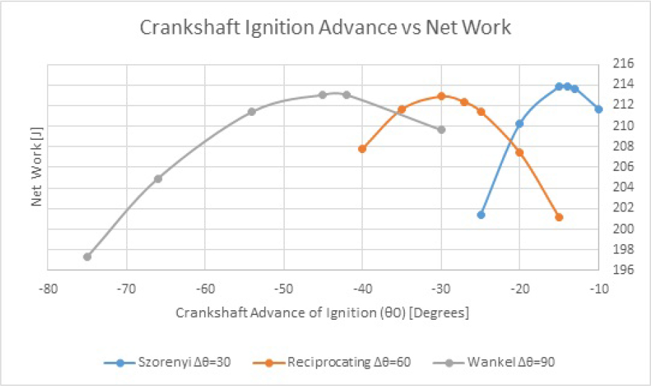
Variation of net work produced by the Szorenyi engine, Wankel engine and the reciprocating engine at different advance of ignition
Consequently, it is observed in Fig. 7 the net work of the Szorenyi rotary engine is the greatest per working cycle, followed by the Wankel rotary engine and finally the reciprocating engine as summarised in Table 2.
Net work comparison between engines
| Net Work Wnet[J] | |
|---|---|
| Szorenyi | 213.859 |
| Wankel | 213.043 |
| Reciprocating | 212.876 |
P-V diagrams of the three engines at their optimum ignition advance are shown in Fig. 8. This results in a highest maximum pressure for the Szorenyi engine, followed by the Wankel engine. Both maximum pressure and work are higher than the reciprocating engine.
The enclosed areas of the P-V diagram were computed with the result that the Wankel engine ideally produces 0.10% more net work per cycle than the reciprocating engine. Also, the Szorenyi engine ideally produces 0.462% more work per cycle than the equivalent reciprocating engine.

P-V diagram comparison of Szorenyi, Wankel and Reciprocating engine
Furthermore, in Fig. 9, the top pressure of the Wankel engine is 4.58% higher than the reciprocating engine and the Szorenyi engine is 5.515% higher than the same reciprocating engine. This leads to a higher ideal net work per cycle for the Szorenyi engine followed by the Wankel engine and the least net work per cycle is produced by the reciprocating engine.

Pressure comparison in a complete cycle of the Szorenyi, Wankel and reciprocating engines
4.3 Thermal Efficiency
Thermal efficiency was calculated for the Szorenyi, Wankel and the reciprocating engine. The results are shown in Table 3.
Fuel conversion efficiency comparison between Szorenyi, Wankel and Reciprocating engine
| nf | |
|---|---|
| Szorenyi | 0.474707 |
| Wankel | 0.472900 |
| Reciprocating | 0.472524 |
It can be seen in Table 3 that under the same working conditions, the Wankel engine has a thermal efficiency 0.079% higher than the reciprocating engine. Also, the Szorenyi engine has a thermal efficiency 0.462% higher than the same reciprocating engine.
4.4 Power
Power is a function of time and torque, therefore, for one chamber of each engine, and the three engines rotating at the same speed at the crankshaft, 3000 RPM, will have different chamber variation. Therefore, the ideal power output is stated in Table 4 for each engine at the same crankshaft speed.
Power output comparison of one chamber of the Szorenyi, Wankel and a Piston engine
| Power (W) | |
|---|---|
| Szorenyi | 7128.6 |
| Wankel | 4734.2 |
| Reciprocating | 3547.9 |
5 Conclusions
As a result of mathematical modelling, it is established that:
The Szorenyi engine is more sensitive to changes in the advance of ignition respect to the crankshaft rotation angle than the reciprocating engine and it has a greater effect on the net work produced.
The Szorenyi engine has a shorter rotation of the crankshaft during combustion than the reciprocating and Wankel engines. Therefore, it must have a smaller advance of ignition than the reciprocating and Wankel engine with respect to the crankshaft.
The net work per cycle produced by the Wankel engine is 0.079% higher than the reciprocating engine. Also, the Szorenyi rotary engine is 0.462% higher than the reciprocating engine for the same displaced volume.
The Szorenyi engine higher power output is 100.90% higher than the reciprocating engine. Also, the Wankel engine is 33.43% higher than the reciprocating engine. These differences are created by the net work, thermal efficiency and number of power strokes per crankshaft revolution of each engine when all engines are working at the same crankshaft speed.
Glossary of Terms
| Symbol | Description | Units |
|---|---|---|
| a | crank radius | m |
| A/Fmix | Air-fuel mixture ratio | |
| B | Bore | m |
| C | Efficiency factor for Wiebe equation | |
| CR | Compression ratio | |
| Cp | Specific heat at constant pressure | J/(°K-mol) |
| Cv | Specific heat at constant volume | J/(°K-mol) |
| dP | Pressure change | Pa |
| dT | Temperature change | °K |
| dt | Time change | sec |
| dV | Volume change | m3 |
| dXb | Wiebe function change | |
| e | Eccentricity | m |
| L | Stroke | m |
| l | connecting rod length | m |
| k | Ratio of specific heat | |
| M | Mass | kg |
| m | Wiebe exponent | |
| mAIR | Air mass per volume | kg |
| mf | Fuel mass per volume | kg |
| nf | Thermal efficiency | |
| P | Absolute pressure | Pa |
| Pf | Final pressure | Pa |
| Po | Initial Pressure | Pa |
| QLHV | Lower heating value | MJ |
| R | Gas constant | J/(°K-mol) |
| RAIR | Universal gas constant for air | J/(°K-mol) |
| r | Isosceles triangle vertex displacement inside the Szorenyi engine | |
| Tf | Final temperature | °K |
| To | Initial Temperature | °K |
| V | Volume | m3 |
| VC | Volume at maximum compression (TDC) | cc |
| VT | Total chamber volume | cc |
| Wnet | Net work per cycle of one chamber | J |
| WR | Wankel generating radius | m |
| w | Rotor face width compared to the four leaf clover radius (unity) | |
| Xb | Wiebe function | |
| xd | Total Fraction of Fuel Burned | |
| x | Rectangular coordinates on the X-axis of the rotary engine stator | |
| Y | Rectangular coordinates on the Y-axis of the rotary engine stator | |
| ρAIR | Air density | kg/m3 |
| Fuel mass flow | g/s | |
| β | Generating angle for the Wankel engine stator profile equation | degrees |
| θ | Crankshaft angle | degrees |
| Also the four leaf clover generating angle for the Szorenyi curve | ||
| Δθ | Duration of combustion with respect to the crankshaft position | degrees |
| θ0 | Crankshaft angle at start of combustion | degrees |
References
[1] S. Pehan and B. Kegl. (2001). Rotary Engine Design [SAE Technical Paper 2001-01-3194]. Available: http://dx.doi.org/10. 4271/2001-01-3194Search in Google Scholar
[2] P. Szorenyi, “Hinged rotor internal combustion engine,” U.S. Patent US 6.718.938 B2, Apr. 13, 2004.Search in Google Scholar
[3] Z. Spakovszky, M. Greitzer, and I. Waitz. (2008, October 10). Thermodynamics & Propulsion. Available: http://web.mit.edu/16.unified/www/SPRING/propulsion/notes/node25.htmlSearch in Google Scholar
[4] F. Wankel and E. Hoeppner, “Rotary internal combustion engine,” US Patent 2988065, June 13, 1961.Search in Google Scholar
[5] L. Peng, “Fundamental research on a unique rotary machine,” PhD, School of Graduate Studies, McMaster University, Canada, 1994.Search in Google Scholar
[6] R. W. Richardson, “Automotive Engines for the 1980’s,” in Eaton’s Worldwide Analysis of Future Automotive Power Plants, Eaton Corporation, ed, 1973, 40-41.10.1021/bk-1974-0001.ch009Search in Google Scholar
[7] K. Yamamoto, Rotary Engine. Japan: Toyo Koyo co. Ltd., 1971.Search in Google Scholar
[8] K. Yamamoto, Rotary engine. Hiroshima, Japan: Sankaido, 1981.Search in Google Scholar
[9] T. J. Norman, “A performance model of a spark ignition Wankel engine : including the effects of crevice volumes, gas leakage, and heat transfer,” Master´s Degree, Dept. of Mechanical Engineering, Massachusetts Institute of Technology, 1983.Search in Google Scholar
[10] J. B. Heywood, Internal combustion engine fundamentals vol. 930: Mcgraw-hill New York, 1988.Search in Google Scholar
[11] R. Sierens, R. Baert, D. E. Winterbone, and P. C. Baruah, “A Comprehensive Study of Wankel Engine Performance,” 1983.10.4271/830332Search in Google Scholar
[12] M. Alexandru-Catalin and B. N. S. Liviu-Constantin, “ROTARY INTERNAL COMBUSTION ENGINES,” Universitatii Maritime Constanta. Analele, 2014, 15, 93-99Search in Google Scholar
[13] P. King. (2013, August 2013) The Szorenyi Rotary-the four chamber rotary engine. Autoengineer [Technical Talk]. 4.Search in Google Scholar
[14] J. Heywood and P. Watts, “Parametric studies of Fuel Consumption and NO Emissions of Dilute Spark-Ignition Engine Operation Using a Cycle Simulation,” in Institute of Mechanical Engineers Conference Publication C, 1979, 117-127.Search in Google Scholar
[15] G. H. Abd Alla, “Computer simulation of a four stroke spark ignition engine,” Energy Conversion and Management, 2002, 43, 1044-1047.10.1016/S0196-8904(01)00092-9Search in Google Scholar
[16] A. Boretti, S. Jiang, and J. Scalzo, “A Novel Wankel Engine Featuring Jet Ignition and Port or Direct Injection for Faster and More Complete Combustion Especially Designed for Gaseous Fuels,” SAE Technical Paper 0148-7191, 2015.10.4271/2015-01-0007Search in Google Scholar
[17] M. S. Raju and E. A. Willis, “Three-Dimensional Analysis and Modeling of a Wankel Engine,” SAE Technical Paper 0148-7191, 1991.10.4271/910701Search in Google Scholar
[18] A. Boretti, “CAD/CFD/CAE Modelling of Wankel Engines for UAV,” SAE Technical Paper 0148-7191, 2015.10.4271/2015-01-2466Search in Google Scholar
[19] S. D. Hires, R. J. Tabaczynski, and J. M. Novak, “The Prediction of Ignition Delay and Combustion Intervals for a Homogeneous Charge, Spark Ignition Engine,” SAE transactions, 1978, 1053-1067.10.4271/780232Search in Google Scholar
[20] J. I. Ghojel, “Review of the development and applications of the wiebe function: A tribute to the contribution of ivan wiebe to engine research,” International Journal of Engine Research, 2010, 11, 297-312.10.1243/14680874JER06510Search in Google Scholar
[21] G. Abbaszadehmosayebi and L. Ganippa, “Determination of specific heat ratio and error analysis for engine heat release calculations,” Applied Energy, 6/1/ 2014, 122, 144.10.1016/j.apenergy.2014.01.028Search in Google Scholar
[22] G. Abbaszadehmosayebi and L. Ganippa, “Characterising Wiebe Equation for Heat Release Analysis based on Combustion Burn Factor (Ci),” Fuel, 3/1/ 2014, 119, 30110.1016/j.fuel.2013.11.006Search in Google Scholar
[23] S. Klein and G. Nellis. (2011). Thermodynamics. Available: http://RMIT.eblib.com.au/patron/FullRecord.aspx?p=80713410.1017/CBO9780511994883Search in Google Scholar
[24] S. Klein and G. Nellis, Thermodynamics: Cambridge University Press, 2012.10.1017/CBO9780511994883Search in Google Scholar
© 2019 L.F. Espinosa and P. Lappas, published by De Gruyter.
This work is licensed under the Creative Commons Attribution 4.0 Public License.
Articles in the same Issue
- Chebyshev Operational Matrix Method for Lane-Emden Problem
- Concentrating solar power tower technology: present status and outlook
- Control of separately excited DC motor with series multi-cells chopper using PI - Petri nets controller
- Effect of boundary roughness on nonlinear saturation of Rayleigh-Taylor instability in couple-stress fluid
- Effect of Heterogeneity on Imbibition Phenomena in Fluid Flow through Porous Media with Different Porous Materials
- Electro-osmotic flow of a third-grade fluid past a channel having stretching walls
- Heat transfer effect on MHD flow of a micropolar fluid through porous medium with uniform heat source and radiation
- Local convergence for an eighth order method for solving equations and systems of equations
- Numerical techniques for behavior of incompressible flow in steady two-dimensional motion due to a linearly stretching of porous sheet based on radial basis functions
- Influence of Non-linear Boussinesq Approximation on Natural Convective Flow of a Power-Law Fluid along an Inclined Plate under Convective Thermal Boundary Condition
- A reliable analytical approach for a fractional model of advection-dispersion equation
- Mass transfer around a slender drop in a nonlinear extensional flow
- Hydromagnetic Flow of Heat and Mass Transfer in a Nano Williamson Fluid Past a Vertical Plate With Thermal and Momentum Slip Effects: Numerical Study
- A Study on Convective-Radial Fins with Temperature-dependent Thermal Conductivity and Internal Heat Generation
- An effective technique for the conformable space-time fractional EW and modified EW equations
- Fractional variational iteration method for solving time-fractional Newell-Whitehead-Segel equation
- New exact and numerical solutions for the effect of suction or injection on flow of nanofluids past a stretching sheet
- Numerical investigation of MHD stagnation-point flow and heat transfer of sodium alginate non-Newtonian nanofluid
- A New Finance Chaotic System, its Electronic Circuit Realization, Passivity based Synchronization and an Application to Voice Encryption
- Analysis of Heat Transfer and Lifting Force in a Ferro-Nanofluid Based Porous Inclined Slider Bearing with Slip Conditions
- Application of QLM-Rational Legendre collocation method towards Eyring-Powell fluid model
- Hyperbolic rational solutions to a variety of conformable fractional Boussinesq-Like equations
- MHD nonaligned stagnation point flow of second grade fluid towards a porous rotating disk
- Nonlinear Dynamic Response of an Axially Functionally Graded (AFG) Beam Resting on Nonlinear Elastic Foundation Subjected to Moving Load
- Swirling flow of couple stress fluid due to a rotating disk
- MHD stagnation point slip flow due to a non-linearly moving surface with effect of non-uniform heat source
- Effect of aligned magnetic field on Casson fluid flow over a stretched surface of non-uniform thickness
- Nonhomogeneous porosity and thermal diffusivity effects on stability and instability of double-diffusive convection in a porous medium layer: Brinkman Model
- Magnetohydrodynamic(MHD) Boundary Layer Flow of Eyring-Powell Nanofluid Past Stretching Cylinder With Cattaneo-Christov Heat Flux Model
- On the connection coefficients and recurrence relations arising from expansions in series of modified generalized Laguerre polynomials: Applications on a semi-infinite domain
- An adaptive mesh method for time dependent singularly perturbed differential-difference equations
- On stretched magnetic flow of Carreau nanofluid with slip effects and nonlinear thermal radiation
- Rational exponential solutions of conformable space-time fractional equal-width equations
- Simultaneous impacts of Joule heating and variable heat source/sink on MHD 3D flow of Carreau-nanoliquids with temperature dependent viscosity
- Effect of magnetic field on imbibition phenomenon in fluid flow through fractured porous media with different porous material
- Impact of ohmic heating on MHD mixed convection flow of Casson fluid by considering Cross diffusion effect
- Mathematical Modelling Comparison of a Reciprocating, a Szorenyi Rotary, and a Wankel Rotary Engine
- Surface roughness effect on thermohydrodynamic analysis of journal bearings lubricated with couple stress fluids
- Convective conditions and dissipation on Tangent Hyperbolic fluid over a chemically heating exponentially porous sheet
- Unsteady Carreau-Casson fluids over a radiated shrinking sheet in a suspension of dust and graphene nanoparticles with non-Fourier heat flux
- An efficient numerical algorithm for solving system of Lane–Emden type equations arising in engineering
- New numerical method based on Generalized Bessel function to solve nonlinear Abel fractional differential equation of the first kind
- Numerical Study of Viscoelastic Micropolar Heat Transfer from a Vertical Cone for Thermal Polymer Coating
- Analysis of Bifurcation and Chaos of the Size-dependent Micro–plate Considering Damage
- Non-Similar Comutational Solutions for Double-Diffusive MHD Transport Phenomena for Non-Newtnian Nanofluid From a Horizontal Circular Cylinder
- Mathematical model on distributed denial of service attack through Internet of things in a network
- Postbuckling behavior of functionally graded CNT-reinforced nanocomposite plate with interphase effect
- Study of Weakly nonlinear Mass transport in Newtonian Fluid with Applied Magnetic Field under Concentration/Gravity modulation
- MHD slip flow of chemically reacting UCM fluid through a dilating channel with heat source/sink
- A Study on Non-Newtonian Transport Phenomena in Mhd Fluid Flow From a Vertical Cone With Navier Slip and Convective Heating
- Penetrative convection in a fluid saturated Darcy-Brinkman porous media with LTNE via internal heat source
- Traveling wave solutions for (3+1) dimensional conformable fractional Zakharov-Kuznetsov equation with power law nonlinearity
- Semitrailer Steering Control for Improved Articulated Vehicle Manoeuvrability and Stability
- Thermomechanical nonlinear stability of pressure-loaded CNT-reinforced composite doubly curved panels resting on elastic foundations
- Combination synchronization of fractional order n-chaotic systems using active backstepping design
- Vision-Based CubeSat Closed-Loop Formation Control in Close Proximities
- Effect of endoscope on the peristaltic transport of a couple stress fluid with heat transfer: Application to biomedicine
- Unsteady MHD Non-Newtonian Heat Transfer Nanofluids with Entropy Generation Analysis
- Mathematical Modelling of Hydromagnetic Casson non-Newtonian Nanofluid Convection Slip Flow from an Isothermal Sphere
- Influence of Joule Heating and Non-Linear Radiation on MHD 3D Dissipating Flow of Casson Nanofluid past a Non-Linear Stretching Sheet
- Radiative Flow of Third Grade Non-Newtonian Fluid From A Horizontal Circular Cylinder
- Application of Bessel functions and Jacobian free Newton method to solve time-fractional Burger equation
- A reliable algorithm for time-fractional Navier-Stokes equations via Laplace transform
- A multiple-step adaptive pseudospectral method for solving multi-order fractional differential equations
- A reliable numerical algorithm for a fractional model of Fitzhugh-Nagumo equation arising in the transmission of nerve impulses
- The expa function method and the conformable time-fractional KdV equations
- Comment on the paper: “Thermal radiation and chemical reaction effects on boundary layer slip flow and melting heat transfer of nanofluid induced by a nonlinear stretching sheet, M.R. Krishnamurthy, B.J. Gireesha, B.C. Prasannakumara, and Rama Subba Reddy Gorla, Nonlinear Engineering 2016, 5(3), 147-159”
- Three-Dimensional Boundary layer Flow and Heat Transfer of a Fluid Particle Suspension over a Stretching Sheet Embedded in a Porous Medium
- MHD three dimensional flow of Oldroyd-B nanofluid over a bidirectional stretching sheet: DTM-Padé Solution
- MHD Convection Fluid and Heat Transfer in an Inclined Micro-Porous-Channel