Scattering of a single plasmon polariton by multiple atoms for in-plane control of light
-
Rituraj

 ,
Meir Orenstein
,
Meir Orenstein

Abstract
We study the interaction of a single photon in a surface plasmon polariton mode with multiple atoms. We propose a system of two atoms to achieve a tunable scattering from subscattering to superscattering regimes by changing the angle of the incident photon. We also demonstrate a perfect electromagnetically-induced transparency using two atoms with two-level structures. The proposed framework is efficiently scalable to a system with a large number of atoms and opens up the possibility of designing novel atom-based optical devices. We design an atomically thin parabolic mirror to focus single photons and form a quantum mirage in a cavity built from atoms.
1 Introduction
Photon–atom interaction is an important subject with considerable theoretical and practical interests [1], [2], [3]. With the development of nanotechnology it has now become possible to tailor this interaction by designing nanophotonic structures with unique optical properties as well as artificial atoms like a superconducting qubit, quantum dot or a Rydberg atom in a highly excited state [4], [5], [6]. In recent years there have been numerous studies investigating the coherent scattering of a few photon Fock states by an atom [7], [8], [9], [10], [11], [12], [13], [14], [15], [16]. Most of these studies, however, are concerned with a single or a few atoms coupled to one dimensional (1D) continuum of photonic modes of the waveguide [7], [8], [9], [10], [11], [12], [13], [14], [17]. It has been shown that a two-level atom coupled to a waveguide acts as a perfect reflector near the resonant frequency, despite its subwavelength size. Similarly, it has been shown that an atom exhibits a cross section much larger than its physical dimensions for single photon scattering in free space near the resonant frequency [16]. Unlike a 1D waveguide, higher dimensionality provides much richer opportunities of manipulating photons through careful geometric arrangement of atoms [18]. Still, very few works have been done regarding scattering of single photons in two (2D) or three dimensions (3D) by multiple atoms.
In a recent work, we presented a general model for the scattering of surface plasmon polariton (SPP) mode by a single atom (in general any two-level quantum system) without making the usual dipole approximation [15]. Since the coupling of the atom to the slow surface modes is much stronger than its coupling to the free space modes, the system essentially represents an atom interacting with a 2D photonic environment. In the current work, we further develop the formalism to compute the scattering properties for a more complicated scenario of multiple atoms coupled to a single photon in the SPP mode. The proposed model is general and includes all the multiple scattering events. The 2D setting with multiple atoms allows us to implement complex photon based quantum circuitry, and here we exemplify it by a few basic examples. We show that a system of two atoms can be tuned to exhibit either subscattering or superscattering by simply changing the photon angle of incidence. We also achieve a perfect atom cloaking with zero scattering at a certain frequency between the resonant frequency of the two atoms. This is different from the usual electromagnetically-induced transparency (EIT) which is based on interference between the transition paths in an atom with at least a three-level structure [1], [19], [20], [21]. We further explore the possibilities of designing novel atom-based optical devices to manipulate single photons and demonstrate multiple atoms based single photon focusing and the formation of quantum mirage in a 2D cavity like system.
2 Mathematical formulation
Here, we develop the formalism for a system of N two-level atoms coupled to a single photon in 2D SPP mode. An atom–SPP system is shown schematically in Figure 1 for two atoms. The infinite 2D surface that supports the SPP mode (shown in green) is taken to be the
where,
where,
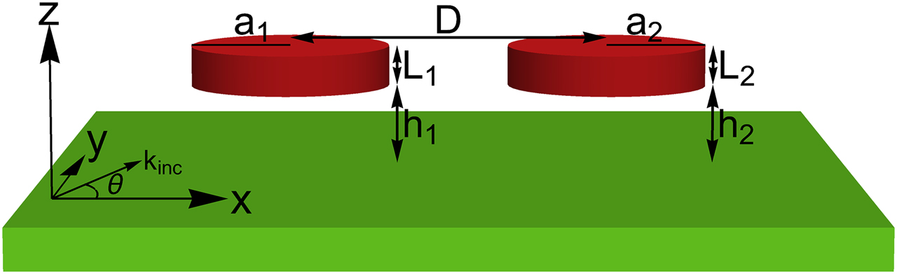
Two atoms (shown in red) coupled to the surface plasmon polariton (SPP) mode of an infinite two dimensional (2D) surface (shown in green). The surface is the
We assume that the atoms couple only to the SPP mode and ignore coupling to the free-space electromagnetic modes. This assumption is well justified since the near field coupling to the SPP modes is much stronger than coupling to the free-space modes. It is also assumed that the atoms do not directly interact with each other. Starting with the standard minimal coupling Hamiltonian, for resonant coupling near the surface plasmon frequency, we can show that the light–matter interaction in the atom–SPP system can be described by the following spatial domain Hamiltonian [15]:
where,
where, e and m are respectively the charge and the rest mass of the electron,
Consider an incident SPP photon with a wavevector q interacting with the atoms, the resulting stationary state can then be written as:
where,
Taking 2D Laplacian
Writing in dimensionless units by defining
Following the standard procedure of computing scattering eigenstates, far away from the atoms where
In Eq. (12), the incident wave
where,
In the above expression for the total field
where,
The above expression can be interpreted as follows. The jth atom sees the combination of the incident plane wave and the waves scattered by all the other atoms as its total incident wave and only scatters the
Repeating this for all the atoms
3 Results
Having presented a general framework to compute the scattering eigenstates of N atoms coupled to the 2D SPP mode, in this section we study a few interesting applications involving light manipulation using atoms.
3.1 Subscattering and superscattering
As the first case, we examine the interaction of a single SPP with two quantum dots with subwavelength horizontal separation. We choose the following parameters for the quantum dots:
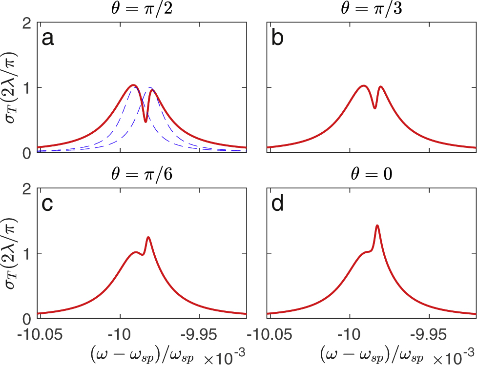
Scattering cross section of the system of two atoms coupled to the surface plasmon polariton (SPP) mode as shown in Figure 1, plotted as a function of frequency for different angles of incidence (plotted in red). The dotted blue curves show the scattering amplitudes
The dotted blue curves in Figure 2a show the individual atomic scattering cross sections
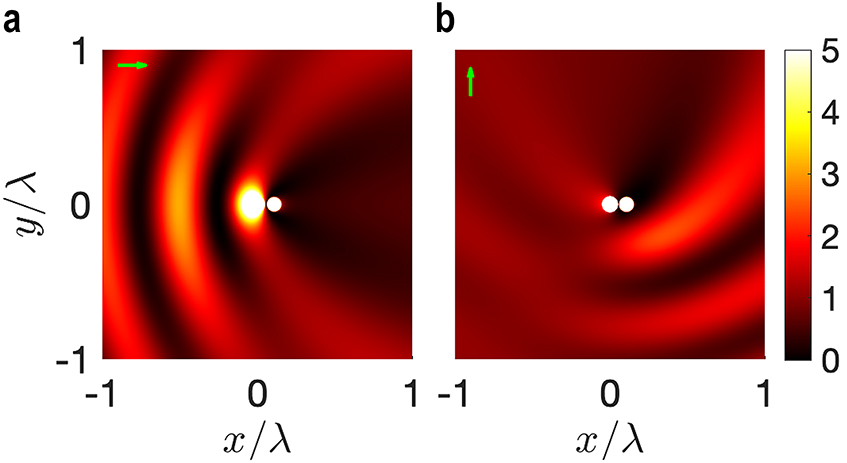
Total field intensity
3.2 Perfect atom cloaking
In the previous section, even though we observe an EIT-like behavior, the scattering cross section does not go to zero. One of the conditions required to obtain a perfect scattering cancellation for a system of two resonators as pointed out in Ref. [36] is to have identical radiation profile for the subradiant and superradiant eigenmodes or equivalently for the two resonators. It is possible to achieve this condition in our system, where the two atoms predominantly couple to the same 2D surface mode, by aligning them horizontally and displacing vertically as shown in Figure 4a. The two quantum dots are identical to those of the previous section
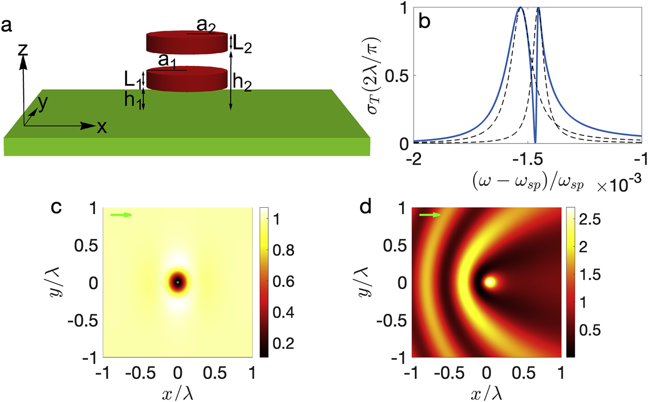
(a) The system of two horizontally aligned quantum dots coupled to the surface plasmon polariton (SPP) mode. (b) Scattering cross section
Figure 4c and d show the squared field amplitude
3.3 Large structures
Having looked at the system of two atoms with subwavelength separation to achieve control and tuning of the scattering in the previous sections, now we design larger atomic optical devices to manipulate single photons in useful ways. In particular, we demonstrate an atomically thin parabolic mirror which concentrates light at its focus [43], [44], [45], [46] and quantum mirage formation in an elliptical cavity like structure [47]. For the following computation, all the quantum dots are assumed to be identical with the same parameter values used in Section 3.1 and detuning
Figure 5 shows the results for the parabolic mirror, with N identical atoms uniformly spaced along the parabola
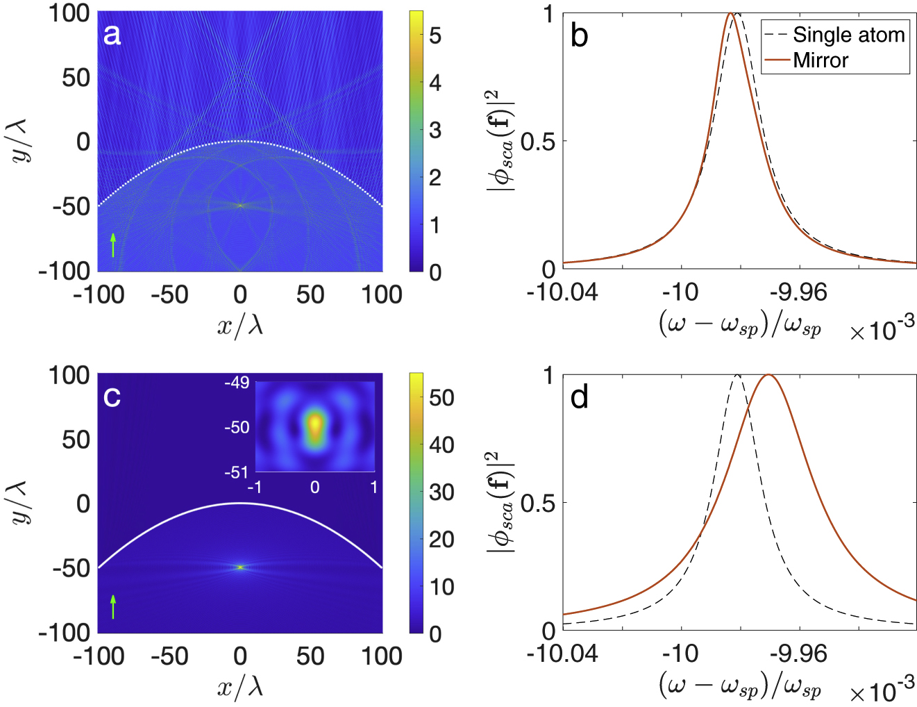
Total field intensity
Finally, we discuss an interesting case of quantum mirage formation [47] for a system of 150 identical atoms uniformly spaced along the circumference of an ellipse
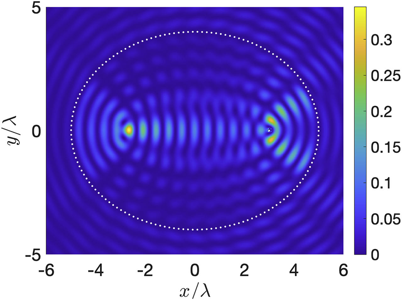
Total field intensity
4 Conclusion
We have demonstrated the possibility of realizing optical devices using multiple atoms interacting with a surface plasmon polariton. Such atomic structures are not only the smallest possible realization of optical structures but also offer unprecedented control over the optical response as compared to the conventional dielectric structures. Among various examples that we have shown, we have realized, for the first time, a perfect EIT for 2D SPP mode using only two-level atoms unlike the usual EIT which requires at least three-level quantum system. The proposed EIT scheme is general and could also be applied to cloak a large number of atoms.
Funding source: U.S. Department of Defense
Award Identifier / Grant number: N00014-17-1-3030
Acknowledgment
This work is supported by a Vannevar Bush Faculty Fellowship from the U. S. Department of Defense (Grant No. N00014-17-1-3030). Rituraj acknowledges the support from a Stanford Graduate Fellowship.
Author contribution: All the authors have accepted responsibility for the entire content of this submitted manuscript and approved submission.
Research funding: This work is supported by a Vannevar Bush Faculty Fellowship from the U. S. Department of Defense (Grant No. N00014-17-1-3030).
Conflict of interest statement: The authors declare no conflicts of interest regarding this article.
References
[1] M. O. Scully and M. S. Zubairy, Quantum Optics, 1999.10.1119/1.19344Search in Google Scholar
[2] D. F. Walls and G. J. Milburn, Quantum Optics, Springer Science & Business Media, 2007.10.1007/978-3-540-28574-8Search in Google Scholar
[3] J. L. O’brien, A. Furusawa, and J. Vučković, “Photonic quantum technologies,” Nat. Photonics, vol. 3, no. 12, p. 687, 2009.10.1038/nphoton.2009.229Search in Google Scholar
[4] A. Goban, C. L. Hung, S. P. Yu, et al., “Atom–light interactions in photonic crystals,” Nat. Commun., vol. 5, p. 3808, 2014, https://doi.org/10.1038/ncomms4808.Search in Google Scholar
[5] A. F. Van Loo, A. Fedorov, K. Lalumiere, B. C. Sanders, A. Blais, and A. Wallraff, “Photon-mediated interactions between distant artificial atoms,” Science, vol. 342, no. 6165, pp. 1494–1496, 2013, https://doi.org/10.1126/science.1244324.Search in Google Scholar
[6] A. V. Gorshkov, J. Otterbach, M. Fleischhauer, T. Pohl, and M. D. Lukin, “Photon-photon interactions via Rydberg blockade,” Phys. Rev. Lett., vol. 107, no. 13, p. 133602, 2011, https://doi.org/10.1103/physrevlett.107.133602.Search in Google Scholar
[7] J. T. Shen and S. Fan, “Coherent photon transport from spontaneous emission in one-dimensional waveguides,” Opt. Lett., vol. 30, no. 15, pp. 2001–2003, 2005, https://doi.org/10.1364/ol.30.002001.Search in Google Scholar
[8] J. T. Shen and S. Fan, “Coherent single photon transport in a one-dimensional waveguide coupled with superconducting quantum bits,” Phys. Rev. Lett., vol. 95, no. 21, p. 213001, 2005, https://doi.org/10.1103/physrevlett.95.213001.Search in Google Scholar
[9] S. Fan, Ş. E. Kocabaş, and J. T. Shen, “Input-output formalism for few-photon transport in one-dimensional nanophotonic waveguides coupled to a qubit,” Phys. Rev., vol. 82, no. 6, p. 063821, 2010, https://doi.org/10.1103/physreva.82.063821.Search in Google Scholar
[10] P. Longo, P. Schmitteckert, and K. Busch, “Dynamics of photon transport through quantum impurities in dispersion-engineered one-dimensional systems,” J. Opt. Pure Appl. Opt., vol. 11, no. 11, p. 114009, 2009, https://doi.org/10.1088/1464-4258/11/11/114009.Search in Google Scholar
[11] L. Zhou, Z. R. Gong, Y. X. Liu, C. P. Sun, and F. Nori, “Controllable scattering of a single photon inside a one-dimensional resonator waveguide,” Phys. Rev. Lett., vol. 101, no. 10, p. 100501, 2008, https://doi.org/10.1103/physrevlett.101.100501.Search in Google Scholar
[12] J. Q. Liao, Z. R. Gong, L. Zhou, Y. X. Liu, C. P. Sun, and F. Nori, “Controlling the transport of single photons by tuning the frequency of either one or two cavities in an array of coupled cavities,” Phys. Rev., vol. 81, no. 4, p. 042304, 2010, https://doi.org/10.1103/physreva.81.042304.Search in Google Scholar
[13] D. Witthaut and A. S. Sørensen, “Photon scattering by a three-level emitter in a one-dimensional waveguide,” New J. Phys., vol. 12, no. 4, p. 043052, 2010, https://doi.org/10.1088/1367-2630/12/4/043052.Search in Google Scholar
[14] H. Zheng, D. J. Gauthier, and H. U. Baranger, “Waveguide-QED-based photonic quantum computation,” Phys. Rev. Lett., vol. 111, no. 9, p. 090502, 2013, https://doi.org/10.1103/physrevlett.111.090502.Search in Google Scholar
[15] M. O. Rituraj and S. Fan, “Two-level quantum system as a macroscopic scatterer for ultraconfined two-dimensional photonic modes,” Phys. Rev., vol. 102, no. 1, p. 013717, 2020, https://doi.org/10.1103/physreva.102.013717.Search in Google Scholar
[16] J. Liu, M. Zhou, and Z. Yu, “Quantum scattering theory of a single-photon Fock state in three-dimensional spaces,” Opt. Lett., vol. 41, no. 18, pp. 4166–4169, 2016, https://doi.org/10.1364/ol.41.004166.Search in Google Scholar
[17] L. Zhou, H. Dong, Y. X. Liu, C. P. Sun, and F. Nori, “Quantum supercavity with atomic mirrors,” Phys. Rev., vol. 78, no. 6, p. 063827, 2008, https://doi.org/10.1103/physreva.78.063827.Search in Google Scholar
[18] E. Shahmoon, D. S. Wild, M. D. Lukin, and S. F. Yelin, “Cooperative resonances in light scattering from two-dimensional atomic arrays,” Phys. Rev. Lett., vol. 118, no. 11, p. 113601, 2017, https://doi.org/10.1103/physrevlett.118.113601.Search in Google Scholar
[19] S. E. Harris, J. E. Field, and A. Imamoğlu, “Nonlinear optical processes using electromagnetically induced transparency,” Phys. Rev. Lett., vol. 64, no. 10, p. 1107, 1990, https://doi.org/10.1103/physrevlett.64.1107.Search in Google Scholar
[20] K. J. Boller, A. Imamoğlu, and S. E. Harris, “Observation of electromagnetically induced transparency,” Phys. Rev. Lett., vol. 66, no. 20, p. 2593, 1991, https://doi.org/10.1103/physrevlett.66.2593.Search in Google Scholar
[21] M. Fleischhauer, A. Imamoğlu, and J. P. Marangos, “Electromagnetically induced transparency: Optics in coherent media,” Rev. Mod. Phys., vol. 77, no. 2, p. 633, 2005, https://doi.org/10.1103/revmodphys.77.633.Search in Google Scholar
[22] K. J. Blow, R. Loudon, S. J. D. Phoenix, and T. J. Shepherd, “Continuum fields in quantum optics,” Phys. Rev., vol. 42, no. 7, p. 4102, 1990, https://doi.org/10.1103/physreva.42.4102.Search in Google Scholar
[23] B. A. Ferreira, B. Amorim, A. J. Chaves, and N. M. R. Peres, “Quantization of graphene plasmons,” Phys. Rev., vol. 101, no. 3, p. 033817, 2020, https://doi.org/10.1103/physreva.101.033817.Search in Google Scholar
[24] M. S. Tame, K. R. McEnery, Ş. K. Özdemir, J. Lee, S. A. Maier, and M. S. Kim, “Quantum plasmonics,” Nat. Phys., vol. 9, no. 6, pp. 329–340, 2013, https://doi.org/10.1038/nphys2615.Search in Google Scholar
[25] A. Archambault, F. Marquier, J. J. Greffet, and C. Arnold, “Quantum theory of spontaneous and stimulated emission of surface plasmons,” Phys. Rev. B, vol. 82, no. 3, p. 035411, 2010, https://doi.org/10.1103/physrevb.82.035411.Search in Google Scholar
[26] W. L. Barnes, A. Dereux, and T. W. Ebbesen, “Surface plasmon subwavelength optics,” Nature, vol. 424, no. 6950, pp. 824–830, 2003, https://doi.org/10.1038/nature01937.Search in Google Scholar
[27] E. N. Economou, “Surface plasmons in thin films,” Phys. Rev., vol. 182, no. 2, p. 539, 1969, https://doi.org/10.1103/physrev.182.539.Search in Google Scholar
[28] M. Jablan, M. Soljačić, and H. Buljan, “Plasmons in graphene: Fundamental properties and potential applications,” Proc. IEEE, vol. 101, no. 7, pp. 1689–1704, 2013, https://doi.org/10.1109/jproc.2013.2260115.Search in Google Scholar
[29] E. A. Power and T. Thirunamachandran, “On the nature of the Hamiltonian for the interaction of radiation with atoms and molecules: (e/mc) p.a, - μe, and all that,” Am. J. Phys., vol. 46, no. 4, pp. 370–378, 1978, https://doi.org/10.1119/1.11313.Search in Google Scholar
[30] V. I. Yudson and P. Reineker, “Multiphoton scattering in a one-dimensional waveguide with resonant atoms,” Phys. Rev., vol. 78, no. 5, p. 052713, 2008, https://doi.org/10.1103/physreva.78.052713.Search in Google Scholar
[31] J. R. Taylor, Scattering Theory: The Quantum Theory of Nonrelativistic Collisions, Courier Corporation, 2006.Search in Google Scholar
[32] G. O. Olaofe, “Scattering by an arbitrary configuration of parallel circular cylinders,” JOSA, vol. 60, no. 9, pp. 1233–1236, 1970, https://doi.org/10.1364/josa.60.001233.Search in Google Scholar
[33] D. Felbacq, G. Tayeb, and D. Maystre, “Scattering by a random set of parallel cylinders,” JOSA A, vol. 11, no. 9, pp. 2526–2538, 1994, https://doi.org/10.1364/josaa.11.002526.Search in Google Scholar
[34] G. O. Olaofe, “Scattering by two cylinders,” Radio Sci., vol. 5, no. 11, pp. 1351–1360, 1970, https://doi.org/10.1029/rs005i011p01351.Search in Google Scholar
[35] A. S. Baltenkov and A. Z. Msezane, “Electronic quantum confinement in cylindrical potential well,” Eur. Phys. J. D, vol. 70, no. 4, p. 81, 2016, https://doi.org/10.1140/epjd/e2016-60728-2.Search in Google Scholar
[36] L. Verslegers, Z. Yu, Z. Ruan, P. B. Catrysse, and S. Fan, “From electromagnetically induced transparency to superscattering with a single structure: A coupled-mode theory for doubly resonant structures,” Phys. Rev. Lett., vol. 108, no. 8, p. 083902, 2012, https://doi.org/10.1103/physrevlett.108.083902.Search in Google Scholar
[37] R. G. DeVoe and R. G. Brewer, “Observation of superradiant and subradiant spontaneous emission of two trapped ions,” Phys. Rev. Lett., vol. 76, no. 12, p. 2049, 1996, https://doi.org/10.1103/physrevlett.76.2049.Search in Google Scholar
[38] R. H. Dicke, “Coherence in spontaneous radiation processes,” Phys. Rev., vol. 93, no. 1, p. 99, 1954, https://doi.org/10.1103/physrev.93.99.Search in Google Scholar
[39] S. H. Autler and C. H. Townes, “Stark effect in rapidly varying fields,” Phys. Rev., vol. 100, no. 2, p. 703, 1955, https://doi.org/10.1103/physrev.100.703.Search in Google Scholar
[40] D. D. Smith, H. Chang, K. A. Fuller, A. T. Rosenberger, and R. W. Boyd, “Coupled-resonator-induced transparency,” Phys. Rev., vol. 69, no. 6, p. 063804, 2004, https://doi.org/10.1103/physreva.69.063804.Search in Google Scholar
[41] B. Peng, Ş. K. Özdemir, W. Chen, F. Nori, and L. Yang, “What is and what is not electromagnetically induced transparency in whispering-gallery microcavities,” Nat. Commun., vol. 5, no. 1, pp. 1–9, 2014, https://doi.org/10.1038/ncomms6082.Search in Google Scholar
[42] P. Ginzburg and M. Orenstein, “Slow light and voltage control of group velocity in resonantly coupled quantum wells,” Opt. Express, vol. 14, no. 25, pp. 12467–12472, 2006, https://doi.org/10.1364/oe.14.012467.Search in Google Scholar
[43] A. Vakil and N. Engheta, “One-atom-thick reflectors for surface plasmon polariton surface waves on graphene,” Opt. Commun., vol. 285, no. 16, pp. 3428–3430, 2012, https://doi.org/10.1016/j.optcom.2012.02.029.Search in Google Scholar
[44] G. Alber, J. Z. Bernád, M. Stobińska, L. L. Sánchez-Soto, and G. Leuchs, “QED with a parabolic mirror,” Phys. Rev., vol. 88, no. 2, p. 023825, 2013, https://doi.org/10.1103/physreva.88.023825.Search in Google Scholar
[45] L. H. Ford and N. F. Svaiter, “Focusing vacuum fluctuations,” Phys. Rev., vol. 62, no. 6, p. 062105, 2000, https://doi.org/10.1103/physreva.62.062105.Search in Google Scholar
[46] P. N. Melentiev, A. A. Kuzin, D. V. Negrov, and V. I. Balykin, “Diffraction-limited focusing of plasmonic wave by a parabolic mirror,” Plasmonics, vol. 13, no. 6, pp. 2361–2367, 2018, https://doi.org/10.1007/s11468-018-0762-y.Search in Google Scholar
[47] H. C. Manoharan, C. P. Lutz, and D. M. Eigler, “Quantum mirages formed by coherent projection of electronic structure,” Nature, vol. 403, no. 6769, pp. 512–515, 2000, https://doi.org/10.1038/35000508.Search in Google Scholar
© 2020 Rituraj et al., published by De Gruyter, Berlin/Boston
This work is licensed under the Creative Commons Attribution 4.0 International License.
Articles in the same Issue
- Editorial
- Editorial
- Optoelectronics and Integrated Photonics
- Disorder effects in nitride semiconductors: impact on fundamental and device properties
- Ultralow threshold blue quantum dot lasers: what’s the true recipe for success?
- Waiting for Act 2: what lies beyond organic light-emitting diode (OLED) displays for organic electronics?
- Waveguide combiners for mixed reality headsets: a nanophotonics design perspective
- On-chip broadband nonreciprocal light storage
- High-Q nanophotonics: sculpting wavefronts with slow light
- Thermoelectric graphene photodetectors with sub-nanosecond response times at terahertz frequencies
- High-performance integrated graphene electro-optic modulator at cryogenic temperature
- Asymmetric photoelectric effect: Auger-assisted hot hole photocurrents in transition metal dichalcogenides
- Seeing the light in energy use
- Lasers, Active optical devices and Spectroscopy
- A high-repetition rate attosecond light source for time-resolved coincidence spectroscopy
- Fast laser speckle suppression with an intracavity diffuser
- Active optics with silk
- Nanolaser arrays: toward application-driven dense integration
- Two-dimensional spectroscopy on a THz quantum cascade structure
- Homogeneous quantum cascade lasers operating as terahertz frequency combs over their entire operational regime
- Toward new frontiers for terahertz quantum cascade laser frequency combs
- Soliton dynamics of ring quantum cascade lasers with injected signal
- Fiber Optics and Optical Communications
- Propagation stability in optical fibers: role of path memory and angular momentum
- Perspective on using multiple orbital-angular-momentum beams for enhanced capacity in free-space optical communication links
- Biomedical Photonics
- A fiber optic–nanophotonic approach to the detection of antibodies and viral particles of COVID-19
- Plasmonic control of drug release efficiency in agarose gel loaded with gold nanoparticle assemblies
- Metasurfaces for biomedical applications: imaging and sensing from a nanophotonics perspective
- Hyperbolic dispersion metasurfaces for molecular biosensing
- Fundamentals of Optics
- A Tutorial on the Classical Theories of Electromagnetic Scattering and Diffraction
- Reflectionless excitation of arbitrary photonic structures: a general theory
- Optimization Methods
- Multiobjective and categorical global optimization of photonic structures based on ResNet generative neural networks
- Machine learning–assisted global optimization of photonic devices
- Artificial neural networks for inverse design of resonant nanophotonic components with oscillatory loss landscapes
- Adjoint-optimized nanoscale light extractor for nitrogen-vacancy centers in diamond
- Topological Photonics
- Non-Hermitian and topological photonics: optics at an exceptional point
- Topological photonics: Where do we go from here?
- Topological nanophotonics for photoluminescence control
- Anomalous Anderson localization behavior in gain-loss balanced non-Hermitian systems
- Quantum computing, Quantum Optics, and QED
- Quantum computing and simulation
- NIST-certified secure key generation via deep learning of physical unclonable functions in silica aerogels
- Thomas–Reiche–Kuhn (TRK) sum rule for interacting photons
- Macroscopic QED for quantum nanophotonics: emitter-centered modes as a minimal basis for multiemitter problems
- Generation and dynamics of entangled fermion–photon–phonon states in nanocavities
- Polaritonic Tamm states induced by cavity photons
- Recent progress in engineering the Casimir effect – applications to nanophotonics, nanomechanics, and chemistry
- Enhancement of rotational vacuum friction by surface photon tunneling
- Plasmonics and Polaritonics
- Shrinking the surface plasmon
- Polariton panorama
- Scattering of a single plasmon polariton by multiple atoms for in-plane control of light
- A metasurface-based diamond frequency converter using plasmonic nanogap resonators
- Selective excitation of individual nanoantennas by pure spectral phase control in the ultrafast coherent regime
- Semiconductor quantum plasmons for high frequency thermal emission
- Origin of dispersive line shapes in plasmon-enhanced stimulated Raman scattering microscopy
- Epitaxial aluminum plasmonics covering full visible spectrum
- Metaoptics
- Metamaterials with high degrees of freedom: space, time, and more
- The road to atomically thin metasurface optics
- Active nonlocal metasurfaces
- Giant midinfrared nonlinearity based on multiple quantum well polaritonic metasurfaces
- Near-field plates and the near zone of metasurfaces
- High-efficiency metadevices for bifunctional generations of vectorial optical fields
- Printing polarization and phase at the optical diffraction limit: near- and far-field optical encryption
- Optical response of jammed rectangular nanostructures
- Dynamic phase-change metafilm absorber for strong designer modulation of visible light
- Arbitrary polarization conversion for pure vortex generation with a single metasurface
- Enhanced harmonic generation in gases using an all-dielectric metasurface
- Monolithic metasurface spatial differentiator enabled by asymmetric photonic spin-orbit interactions