Technology and analysis of 08Cr9W3Co3VNbCuBN steel large diameter thick wall pipe welding process
-
Feng Wang
 ,
Fengshou Zhang
,
Fengshou Zhang

Abstract
In this article, the welding technology of large diameter thick wall 08Cr9W3Co3VNbCuBN (G115) heat-resistant steel pipes for the main steam pipe of a 650°C ultra-supercritical power station boiler has been investigated, and the mechanical properties and microstructure of welded joints at different wall thickness positions have also been analyzed. The results show that the mechanical properties of narrow gap welded joint of 115 mm thick large diameter 08Cr9W3Co3VNbCuBN heat-resistant steel pipe obtained by Gas tungsten arc welding (GTAW) + shielded metal arc welding (SMAW) + automatic submerged arc welding (SAW) can meet the requirements of relevant standards after tempering at 780°C. The tensile failure of the welded joint occurs in the base metal zone far away from the weld, an obvious necking phenomenon appears at the fracture position, and the welded joint has good tensile properties. No δ ferrite phase was found in the weld and heat-affected zone (HAZ). The microstructures of each zone are tempered martensite.
1 Introduction
With the development of economy and society,energy saving and emission reduction have become the two major themes in the development of the modern industry. Ultra-supercritical thermal power unit technology with high energy efficiency and low emission has gradually become the development direction of thermal power unit technology.
In 2017, the National Energy Administration of China officially approved the demonstration project of Da tang Yuncheng 630°C ultra-supercritical coal-fired unit, which is currently the thermal power unit with the highest steam parameters in the world. The efficiency of thermal power units depends mainly on the steam temperature and steam pressure of the units, and the efficiency of the generating units can be effectively improved only by increasing the steam parameters. To achieve reliable operation of units with higher steam parameters, it is necessary to research and develop high-temperature heat-resistant materials that are compatible with high steam parameters. But for now, the development of heat-resistant steel in high-temperature sections is the key factor restricting the development of thermal power units to high parameters, and the large diameter thick wall boiler tube is the bottleneck [1,2,3].
A new type of martensitic heat-resistant steel 08Cr9W3Co3VNbCuBN (G115) was jointly developed by the Iron and Steel Research Institute and Bao Steel group. The steel adopts selective strengthening to effectively control the growth rate of M23C6 carbides during service by reasonably controlling the ratio of B to N, adding an appropriate amount of Cu further increases the precipitation strengthening effect. The durable extrapolated strength at 650°C for 10,000 h is 1.5 times that of P92 steel, and its resistance to high-temperature steam oxidation and welding ability is equivalent to that of P92 steel [4]. At present, the research on 08Cr9W3Co3VNbCuBN steel is limited to the manufacturing process and performance of 08Cr9W3Co3VNbCuBN steel base metal and small diameter superheater and reheater tube [5,6,7,8], while the welding technology research of large diameter thick wall 08Cr9W3Co3VNbCuBN steel is rarely reported.
08Cr9W3Co3VNbCuBN steel belongs to the 9% Cr family of heat-resistant steels, and Kumar et al. [9,10] found the presence of δ ferrite with different morphologies in the coarse-grained HAZ (CGHAZ) region of welded joints of 9% Cr family heat-resistant steels [9,10,11,12], and the presence of δ ferrite significantly reduces the impact toughness of welded joints and has a negative impact on the long-term creep strength of welded joints [13].
08Cr9W3Co3VNbCuBN steel contains about 3% Co, 0.8% Cu elements, both of which are austenite stabilizing elements that can inhibit the formation of δ ferrite, but during the performance heat treatment of large diameter thick wall heat-resistant steel pipe, due to the wall thickness and long heating and holding time, there is an obvious temperature gradient at different positions in the pipe diameter direction during cooling, which usually leads to the coarser grain size of the base metal. When welding coarse-grained thick wall 08Cr9W3Co3VNbCuBN steel, if the welding process is not selected properly, micro defects such as δ ferrite phase and carbide precipitation growth along the crystal are easy to appear at the welded joint, which will adversely affect its mechanical properties, especially the impact properties.
In this article, the welding process of 08Cr9W3Co3VNbCuBN heat-resistant pipe with a wall thickness of 115 mm, which can be used for the main steam pipe of 650°C power station boiler, was studied. The mechanical properties and microstructure of narrow gap welded joints of 08Cr9W3Co3VNbCuBN steel pipe at different wall-thickness positions have been detected and analyzed.
2 Experimental procedures
2.1 Materials
The test material is 08Cr9W3Co3VNbCuBN (G115) heat-resistant steel pipe for 650°C power station boiler, with the size of outer diameter 530 mm × 115 mm. The chemical composition of 08Cr9W3Co3VNbCuBN steel pipe is shown in Table 1. According to Table 1, the chemical composition of 08Cr9W3Co3VNbCuBN steel pipe meets the relevant requirements of the group standard T/CISA 003-2017 new martensitic heat-resistant steel 08Cr9W3Co3VNbCuBN seamless steel pipe for power station. The microstructure of 08Cr9W3Co3VNbCuBN steel is typical tempered martensite, as shown in Figure 1.
Chemical composition of the 08Cr9W3Co3VNbCuBN pipe and welding stick (mass fraction, %)
| Element | C | Mn | Si | Cr | W | V | Co | N | B | Cu | Nb | Al | S | P | Fe |
|---|---|---|---|---|---|---|---|---|---|---|---|---|---|---|---|
| Standard value of 08Cr9W3Co3VNbCuBN steel [14] | 0.06–0.10 | 0.27–0.73 | ≤0.5 | 8.5–9.5 | 2.33–3.17 | 0.13–0.27 | 2.85–3.25 | 0.005–0.015 | 0.01–0.022 | 0.4–1.2 | 0.03–0.1 | ≤0.015 | ≤0.01 | ≤0.02 | Bal |
| Measured value of 08Cr9W3Co3VNbCuBN steel pipe | 0.08 | 0.40 | 0.17 | 8.74 | 2.7 | 0.253 | 2.85 | 0.012 | 0.016 | 0.62 | 0.06 | 0.004 | 0.005 | 0.017 | Bal |
| GTR-W93 welding wire | 0.10 | 0.60 | 0.36 | 8.82 | 2.31 | 0.19 | 2.82 | — | — | 0.01 | — | — | 0.004 | 0.009 | Bal |
| GER-93 welding wire | 0.07 | 0.72 | 0.13 | 9.00 | 2.75 | 0.17 | 2.72 | — | — | 0.83 | — | — | 0.004 | 0.006 | Bal |
| GWR-W93 welding wire | 0.11 | 0.77 | 0.11 | 8.52 | 2.68 | 0.20 | 2.89 | — | — | 0.08 | — | — | 0.005 | 0.006 | Bal |

Microstructure of 08Cr9W3Co3VNbCuBN steel. (a) 100X, (b) 500X.
2.2 Welding and post-weld heat treatment process
GTAW, SMAW and SAW methods are used for thick-walled 08Cr9W3Co3VNbCuBN steel pipe. Jing lei GTR-W93 wire electrode with a diameter of Ø2.4 mm was utilized for GTAW, GER-93 welding rod with a diameter of Ø3.2 mm was utilized for SMAW, and GWR-W93 wire electrode with the GXR-93 welding flux was utilized in the SAW process. The chemical composition and mechanical properties of the welding rod (wire) are shown in Tables 1 and 2.
Mechanical properties of the 08Cr9W3Co3VNbCuBN pipe and welding electrodes
| Mechanical properties of elements | Tensile strength (MPa) | Yield strength (MPa) | Elongation, % (portrait) | KV2/J (portrait) | Hardness/HBW |
|---|---|---|---|---|---|
| Standard value of 08Cr9W3Co3VNbCuBN steel [14] | ≥660 | ≥480 | ≥20 | ≥40 | 195–250 |
| Measured value of 08Cr9W3Co3VNbCuBN steel pipe | 675 | 526 | 27 | 121 | 219 |
| GTR-W93 welding wire | 781 | 654 | 22 | 96 | — |
| GER-W93 welding rod | 729 | 596 | 20 | 108 | — |
| GWR-W93 welding wire | 735 | 580 | 25 | 44 | — |
The welding groove of thick-walled 08Cr9W3Co3VNbCuBN steel pipe adopts a double V-shaped narrow gap groove, and the butt width is 31–32 mm. The specific parameters are shown in Figure 2. After the pipe butt joint inspection is qualified, the steel pipe is pre-heated at 200–250°C for 1.5 h. The spot welding is carried out, applying the Ø2.4 mm tungsten electrode, grade WCE-20 (tip sharpening angle, 20–30°) under the DC + polarity.

Schematic diagram of welding groove of thick wall 08Cr9W3Co3VNbCuBN steel pipe.
The protruding length of the tungsten electrode from the porcelain nozzle is less than or equal to 8 mm, and the arc length between the tungsten electrode and the surface of the molten pool is 2–4 mm. Two weld passes with a thickness of 3 mm each are made by GTAW. During the first layer of argon arc welding and manual welding, the pipeline should be filled with argon for protection, and the purity of argon used should be greater than 99.9%. The flow of internal shielding gas is 0.37–0.5 L·s−1 at the beginning and 0.15–0.23 L·s−1 during welding.
There are 46 welding layers in total: the first and second layers are GTAW primer, the 3rd–14th layers are made by SMAW, and the 15th–46th layers are made by SAW. The 3rd, 4th and 5th layers are single-layer single pass welding, the 6th–39th layers are welded with two passes per layer, the 40th–44th are welded with three passes per layer, and the 45th–46th layers are welded with four passes per layer. Table 3 lists specific welding process parameters.
Welding parameter
| Welding mode | Welding layer | Welding technology | Welding wire | Welding current (A) | Arc voltage (V) | Wire feeding speed (cm·min−1) | Welding speed (cm·min−1) | |
|---|---|---|---|---|---|---|---|---|
| Diameter (mm) | Brand | |||||||
| Backing welding | 1–2 | GTAW | 2.4 | GTR-W93 | 110–160 | 10–15 | — | 3–10 |
| Filler welding | 3–14 | SMAW | 3.2 | GER-W93 | 90–135 | 22–25 | — | 14–51 |
| Filler welding + cover welding | 15–46 | SAW | 2.4 | GWR-W93 | 300–380 | 28–35 | 686–857.5 | 26–46 |
During preheating and heat tracing, thermocouples are placed on both sides of the groove, the temperature at the digital display is recorded every 30 min, and the temperature at the edge of the groove is measured and recorded by a contact thermometer. In the process of GTAW and SMAW welding, the interlayer temperature is always maintained in the range of 200–250°C, and in the process of submerged arc welding, the interlayer temperature is always maintained in the range of 200–300°C.
The initial temperature of the martensitic transformation of 08Cr9W3Co3VNbCuBN steel is 375°C, and the completion temperature of martensitic transformation is 255°C [15]. After welding, the temperature is kept at 255°C for 2 h to complete the martensitic transformation, and then, the temperature is increased to 350°C, kept constant for 2 h and cooled slowly.
The overall heat treatment in the furnace is adopted in the post-weld heat treatment. The constant temperature is 775 ± 5°C, the constant temperature time is 11 h, the heating rate is less than 60 K·h−1, the cooling rate is less than 90 K·h−1, and the temperature is decreased to below 300°C by air cooling.
2.3 Sampling location and testing method
After the completion of welding heat treatment, the welded joint is qualified by ultrasonic and X-ray non-destructive testing. With the weld seam as the center along the longitudinal direction of the pipe, the workpiece is cut into eight pieces by wire cutting and numbered 1–8, geometry and dimensions of the corresponding test block as shown in Figure 3a. Six tensile specimens were wire cut out of block No. 1. Four side bending specimens were cut of block No. 8. Eighteen impact specimens were cut out of block No. 3, including nine welding impact specimens and nine HAZ impact specimens. The metallographic sampling position is shown in Figure 3b.

Schematic diagram of sampling position.
After grinding and polishing, the metallographic samples are corroded with FeCl3 hydrochloric acid solution (5 g ferric chloride, 50 mL hydrochloric acid and 100 mL water) and observed under Axio A1m Zeiss optical microscope. The room temperature tensile test was carried out on CMT5105 Mets tensile testing machine according to GB/T228.1-2010. The impact test of welded joints was carried out at room temperature according to GB/T 229-2007 on ZBC2302-C Mets impact testing machine. The notch axis of the HAZ sample passes through the fusion line and is perpendicular to the weld surface, and the notch axis of the weld sample is located in center of the weld and perpendicular to the weld surface. HV-30T Vickers hardness tester is used to test the hardness of different areas of the welded joint profile according to GB/T 9790-2021. Vickers hardness measurement load is 9.8 N. From the fusion line on both sides of the weld, the hardness testing points of HAZ are tested every 0.5 mm.
3 Results and discussion
3.1 Microstructure of welded joints
As shown in Figure 3b, the metallographic samples of base metal, HAZ and weld at different thickness positions of No. 1–3 welded joints section are observed and analyzed. The metallographic morphology of the base metal at different section thickness positions of No. 1–3 welded joints section is shown in Figure 4a1–a3 , where the microstructure is tempered martensite and basically consistent with the metallographic morphology of the raw material of 08Cr9W3Co3VNbCuBN steel pipe shown in Figure 1.
Figure 4b1–b3 shows the metallographic morphology of the HAZ at different locations, where the microstructure is still tempered martensite, but the grain size of the original austenite is significantly finer than that of the base metal. The width of HAZ of narrow gap welded joint of thick-walled 08Cr9W3Co3VNbCuBN steel pipe obtained by GTAW, SMAW and SAW is 2–3 mm, which can be divided into four parts: fusion zone, coarse grain zone, fine grain zone and incomplete recrystallization zone. However, there is no obvious difference in grain morphology in different positions of HAZ of thick-walled 08Cr9W3Co3VNbCuBN steel pipe, which is finer than that of the base metal. In addition, we have marked the relevant grain boundaries with red curves in the figure.
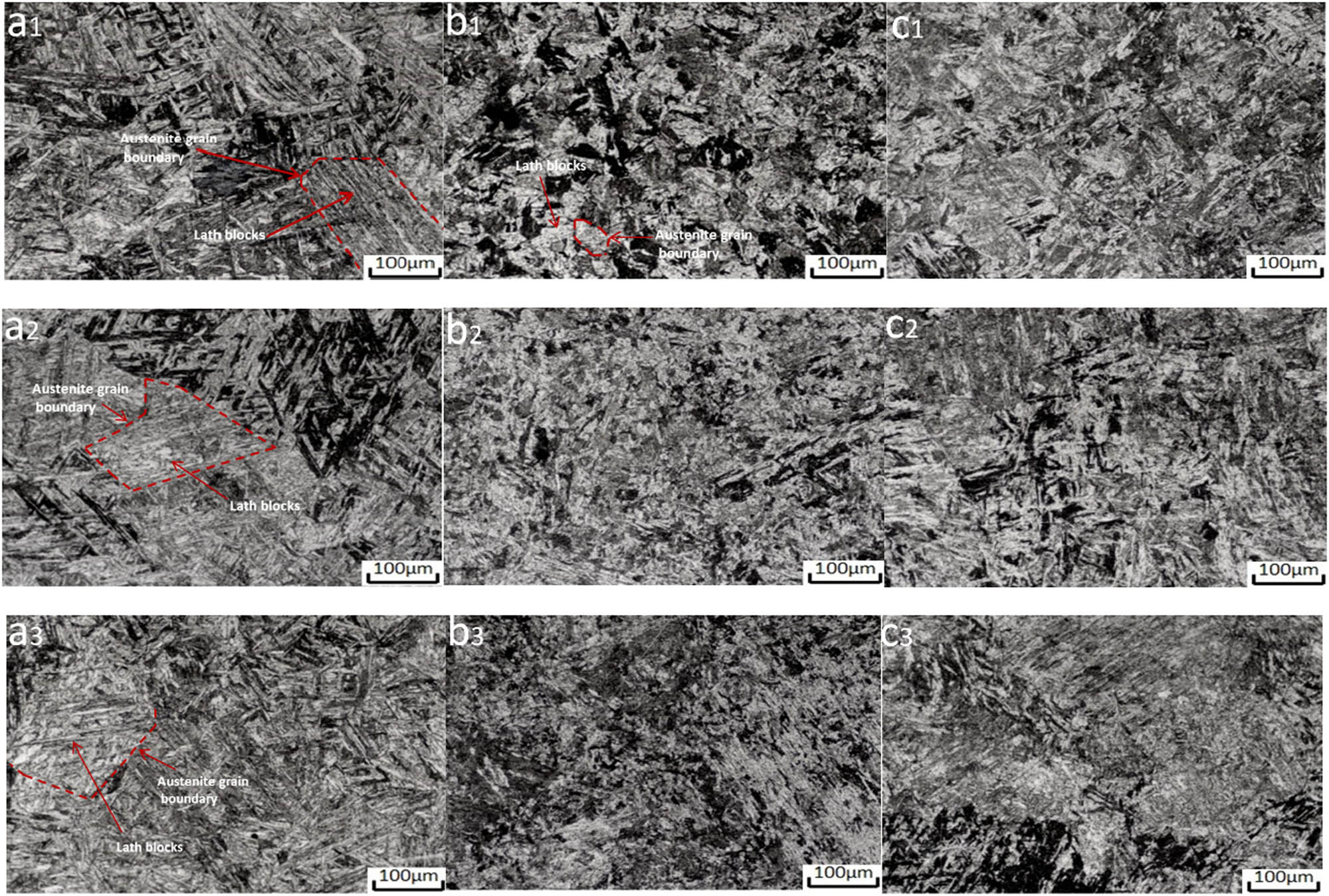
1–3# Metallographic morphology of welded joint section at different thickness positions (a, base metal zone; b, heat affected zone; c, weld zone).
Figure 4c1–c3 shows the metallographic morphology of the weld at different positions; the microstructure is laid of tempered martensite, which consists of a large number of equiaxed crystals and small amounts of columnar crystals. The reason for the smaller amounts of columnar crystals is that the 46 passes of the welded joint are reheated by the subsequent weld bead at the sampling position, resulting in phase transformation and recrystallization of the microstructure at the sampling position, forming a large number of equiaxed crystals.
Both thick-walled 08Cr9W3Co3VNbCuBN base metal and welding metal contain about 9 wt.% Cr and 2.7wt.% W. The results show that too high Cr and W content will lead to the emergence of δ-Fe [16,17], but the Co and Cu elements in 08Cr9W3Co3VNbCuBN steel are austenite stabilizing elements, which can effectively restrain the emergence of δ-Fe. The microstructure of all parts of the welded joint of 08Cr9W3Co3VNbCuBN steel obtained by the welding process described in this article is tempered martensite and no δ-Fe is found.
3.2 Tensile and impact properties of welded joints
As shown in Figure 3a, the No. 1 specimen is stretched at room temperature. The tensile strength of the welded joint is 665–695 MPa; the test meets the requirements of tensile (R m) ≥660 MPa of steel pipe in TCISA 003-2017 standard. The tensile failure of the welded joint occurs in the base metal area away from the weld, and the obvious necking phenomenon appears at the fracture position; welded joint tensile specimen fracture location is shown in Figure 5.

Welded joint tensile specimen fracture location.
No. 8 specimen is subjected to side bending. In accordance with the requirements of TCISA 003-2017 standard in D = 4a, α = 180° bending conditions of the inside and outside surface of the side bending specimens are not seen cracks, to meet the standard requirements.
No. 3 specimen is tested by room temperature impact test according to the different thickness positions of the welded joint section No. 1–3 as shown in Figure 3b. As shown in Figure 6, the impact energy of weld zone of the No. 1–3 welded joint section (as Figure 3b cross section) is 73, 62 and 84 J, respectively, and that of HAZ is 52, 61 and 79 J, respectively.

1–3# Impact energy of weld seam and heat affected zone of welded joint section.
The change pattern of impact performance at different thickness positions is basically the same. The impact energy of the HAZ of the welded joint obtained by GTAW + SMAW + SAW process is the lowest, the impact energy of the weld position is only 52 J, and the impact property of the weld zone is slightly better than that of the HAZ (the lowest 62 J), but also obviously lower than that of the base metal (average 120 J). The impact energy of each region meets the impact performance requirements of steel pipes in the TCISA003-2017 standard (longitudinal impact energy ≥40 J).
3.3 Vickers hardness of welded joints
As shown in Figure 7, the hardness of the welded joint of No. 1–3 shared the same hardness variation law, the hardness of HAZ is significantly higher than that of base metal and weld zone, and the Vickers hardness near the fusion line of HAZ in the section of No. 3 reaches 253 HV. As the measuring point is far away from the weld, its hardness test value decreases gradually, and the hardness value is basically the same as the average hardness of the base metal at about 2.5 mm from the weld fusion line. According to the changes of metallographic structure and hardness, it can be determined that the width of HAZ of narrow gap thick wall 08Cr9W3Co3VNbCuBN welded joint obtained by GTAW, SMAW, and SAW is about 2.5 mm.

1–3# Vickers hardness in different areas of Welded joint section.
Generally, the HAZ can be divided into fusion zone, coarse grain zone, fine grain zone and incomplete recrystallization zone. Since the 08Cr9W3Co3VNbCuBN steel pipe with a wall thickness of 115 mm has been welded in 46 layers by the welding process described in this article, the HAZ of 08Cr9W3Co3VNbCuBN steel has experienced many short-term heating and cooling cycles. During the heating process, the HAZ quickly passes through the Ac1–Ac3 critical zone under the action of welding heat, so that the flake austenite cannot grow in time, and the austenite is mainly spherical, and the austenite grain is refined after a single thermal cycle [18]. In the subsequent thermal cycles, there is no fixed orientation relationship between martensite and spherical austenite, and the precipitated MC-type carbides are pinned to the grain boundary, and finally, the microstructure of HAZ with grain refinement is obtained. At the same time, the presence of Co and Cu elements in G115 steel inhibits the formation of δ ferrite in the weld heat-affected zone. Therefore, the hardness of HAZ is 20–30 HV higher than that of base metal.
4 Conclusions
In this article, the welding process of 08Cr9W3Co3VNbCuBN heat-resistant pipe with a wall thickness of 115 mm, which can be used for the main steams pipe of 650°C power station boiler, is studied, and the mechanical properties and microstructure of narrow gap welded joint of thick-walled 08Cr9W3Co3VNbCuBN steel pipe are tested and analyzed.
The narrow gap welded joint of 115 mm thick large diameter 08Cr9W3Co3VNbCuBN heat-resistant steel pipe obtained by GTAW, SMAW and SAW welding process can meet the requirements of relevant standards.
The width of HAZ of narrow gap welded joint of 115 mm thick large diameter 08Cr9W3Co3VNbCuBN heat-resistant steel pipe obtained by GTAW, SMAW and SAW is about 2.5 mm, and its hardness up to 253HV is significantly higher than that of the weld and base metal area.
The microstructure of the welded joint of 115 mm thick large diameter 08Cr9W3Co3VNbCuBN steel is tempered martensite, and the grain in the welding HAZ is refined, and no δ-Fe is found in all parts of the welded joint.
Acknowledgments
The authors sincerely acknowledge Gao Mengjie and Professor Zhai Yunpu, School of Chemistry, Zhengzhou University, for their support to this research.
-
Funding information: The authors state no funding is involved.
-
Author contributions: Feng Wang – writing-original draft, writing – review & editing, methodology, formal Analysis; Fengshou Zhang – writing – original draft, experimental test & analysis; Jiang Ma – picture drawing & editing; Xizhen Ma – pre-experiment investigations & project equipment supply.
-
Conflict of interest: The authors state no conflict of interest.
References
[1] Liu, Z., S. Cheng, and Q. Wang. Progress of boiler steel for 600°C thermal power units in China, Metallurgical Industry Press, Beijing, 2011.Search in Google Scholar
[2] Yang, S., Z. Liu, and S. Cheng. Performance analysis of key boiler steels for ultra-supercritical thermal power units. Journal of Iron and Steel Research, Vol. 22, 2010, pp. 37–56.Search in Google Scholar
[3] Liu, Z. A steel for 650°C steam temperature ultra-supercritical thermal power unit and its preparation method, National Intellectual Property Office, China, 2014.Search in Google Scholar
[4] Liu, Z. and X. Xie. The Chinese 700°C A-USC development program. Materials for ultra-supercritical and advanced ultra-supercritical power plants, Woodhead Publishing Ltd, Britain, 2017, 715–731.10.1016/B978-0-08-100552-1.00021-XSearch in Google Scholar
[5] Li, H., J. Liang, C. Zhou, and L. Xu. Effect of normalizing temperature on microstructure and room temperature strength of G115 steel. Metal Heat Treatment, Vol. 39, 2018, pp. 71–76.Search in Google Scholar
[6] Xiao, B., L. Xu, L. Zhao, H. Jing, and Y. Han. Tensile mechanical properties, constitutive equations and fracture mechanisms of a novel 9 % chromium tempered martensitic steel at elevated temperatures. Materials Science and Engineering: A, Vol. 690, 2017, pp. 104–119.10.1016/j.msea.2017.02.099Search in Google Scholar
[7] Xu, L., H. Pang, and L. Zhao. Microstructure and mechanical properties of CMT + P welding process on G115 steel. Journal of Welding, Vol. 41, 2020, pp. 1–5.Search in Google Scholar
[8] Cai, H. Y., L. Y. Xu, L. Zhao, Y. D. Han, H. N. Pang, and W. Chen. Cold metal transfer plus pulse (CMT + P) welding of G115 steel: Mechanisms, microstructure, and mechanical properties. Materials Science and Engineering: A, Vol. 843, 2022, id. 143156.10.1016/j.msea.2022.143156Search in Google Scholar
[9] Kumar, S., C. Pandey, and A. Goyal. A microstructural and mechanical behavior study of heterogeneous P91 welded joint. International Journal of Pressure Vessels and Piping, Vol. 185, 2020, id. 104128.10.1016/j.ijpvp.2020.104128Search in Google Scholar
[10] Kumar, S., C. Pandey, and A. Goyal. Effect of post-weld heat treatment and dissimilar filler metal composition on the microstructural developments, and mechanical properties of gas tungsten arc welded joint of P91 steel. International Journal of Pressure Vessels and Piping, Vol. 191, 2021, id. 104373.10.1016/j.ijpvp.2021.104373Search in Google Scholar
[11] Gaurav, D., S. Sachin, and P. Chandan. Study on microstructure and mechanical behavior relationship for laser-welded dissimilar joint of P92 martensitic and 304L austenitic steel. International Journal of Pressure Vessels and Piping, Vol. 196, 2022, id. 104629.10.1016/j.ijpvp.2022.104629Search in Google Scholar
[12] Chandan, P., M. M. Manas, K. Pradeep, and S. Nitin. Dissimilar joining of CSEF steels using autogenous tungsten-inert gas welding and gas tungsten arc welding and their effect on -ferrite evolution and mechanical properties. Journal of Manufacturing Processes, Vol. 31, 2018, pp. 247–259.10.1016/j.jmapro.2017.11.020Search in Google Scholar
[13] Chandan, P. Mechanical and metallurgical characterization of dissimilar P92/SS304 L welded joints under varying heat treatment regimes. Metallurgical and Materials Transactions A, Vol. 51A, No. 5, 2020, pp. 2127–2142.10.1007/s11661-020-05660-0Search in Google Scholar
[14] T/CISA 003-2017. Seamless new martensitic heat-resistant steel tubes and pipes of 08Cr9W3Co3VNbCuBN (G115) for power station, 2017.Search in Google Scholar
[15] Liu, Z., Z. Chen, and H. Bao. Development and engineering of a new generation of martensitic heat-resistant steel G115, Metallurgical Industry Press, Beijing, China, 2020.Search in Google Scholar
[16] Abe, F. Precipitate design for creep strengthening of 9 % Cr tempered martensitic steel for USC power plant. Science and Technology of Advanced Materials, Vol. 9, 2008, pp. 1–15.10.1088/1468-6996/9/1/013002Search in Google Scholar PubMed PubMed Central
[17] Abe, F. and S. Nakazawa. The effect of tungsten on creep. Metallurgical and Materials Transaction A, Vol. 23, 1992, pp. 3025–3034.10.1007/BF02646120Search in Google Scholar
[18] Yugai, S. S., L. M. Klediner, and A. A. Shatsov. Structural heredity in low-carbon martensitic steels. Metal Science and Heat Treatment, Vol. 46, 2004, pp. 539–544.10.1007/s11041-005-0015-5Search in Google Scholar
© 2023 the author(s), published by De Gruyter
This work is licensed under the Creative Commons Attribution 4.0 International License.
Articles in the same Issue
- Research Articles
- First-principles investigation of phase stability and elastic properties of Laves phase TaCr2 by ruthenium alloying
- Improvement and prediction on high temperature melting characteristics of coal ash
- First-principles calculations to investigate the thermal response of the ZrC(1−x)Nx ceramics at extreme conditions
- Study on the cladding path during the solidification process of multi-layer cladding of large steel ingots
- Thermodynamic analysis of vanadium distribution behavior in blast furnaces and basic oxygen furnaces
- Comparison of data-driven prediction methods for comprehensive coke ratio of blast furnace
- Effect of different isothermal times on the microstructure and mechanical properties of high-strength rebar
- Analysis of the evolution law of oxide inclusions in U75V heavy rail steel during the LF–RH refining process
- Simultaneous extraction of uranium and niobium from a low-grade natural betafite ore
- Transfer and transformation mechanism of chromium in stainless steel slag in pedosphere
- Effect of tool traverse speed on joint line remnant and mechanical properties of friction stir welded 2195-T8 Al–Li alloy joints
- Technology and analysis of 08Cr9W3Co3VNbCuBN steel large diameter thick wall pipe welding process
- Influence of shielding gas on machining and wear aspects of AISI 310–AISI 2205 dissimilar stainless steel joints
- Effect of post-weld heat treatment on 6156 aluminum alloy joint formed by electron beam welding
- Ash melting behavior and mechanism of high-calcium bituminous coal in the process of blast furnace pulverized coal injection
- Effect of high temperature tempering on the phase composition and structure of steelmaking slag
- Numerical simulation of shrinkage porosity defect in billet continuous casting
- Influence of submerged entry nozzle on funnel mold surface velocity
- Effect of cold-rolling deformation and rare earth yttrium on microstructure and texture of oriented silicon steel
- Investigation of microstructure, machinability, and mechanical properties of new-generation hybrid lead-free brass alloys
- Soft sensor method of multimode BOF steelmaking endpoint carbon content and temperature based on vMF-WSAE dynamic deep learning
- Mechanical properties and nugget evolution in resistance spot welding of Zn–Al–Mg galvanized DC51D steel
- Research on the behaviour and mechanism of void welding based on multiple scales
- Preparation of CaO–SiO2–Al2O3 inorganic fibers from melting-separated red mud
- Study on diffusion kinetics of chromium and nickel electrochemical co-deposition in a NaCl–KCl–NaF–Cr2O3–NiO molten salt
- Enhancing the efficiency of polytetrafluoroethylene-modified silica hydrosols coated solar panels by using artificial neural network and response surface methodology
- High-temperature corrosion behaviours of nickel–iron-based alloys with different molybdenum and tungsten contents in a coal ash/flue gas environment
- Characteristics and purification of Himalayan salt by high temperature melting
- Temperature uniformity optimization with power-frequency coordinated variation in multi-source microwave based on sequential quadratic programming
- A novel method for CO2 injection direct smelting vanadium steel: Dephosphorization and vanadium retention
- A study of the void surface healing mechanism in 316LN steel
- Effect of chemical composition and heat treatment on intergranular corrosion and strength of AlMgSiCu alloys
- Soft sensor method for endpoint carbon content and temperature of BOF based on multi-cluster dynamic adaptive selection ensemble learning
- Evaluating thermal properties and activation energy of phthalonitrile using sulfur-containing curing agents
- Investigation of the liquidus temperature calculation method for medium manganese steel
- High-temperature corrosion model of Incoloy 800H alloy connected with Ni-201 in MgCl2–KCl heat transfer fluid
- Investigation of the microstructure and mechanical properties of Mg–Al–Zn alloy joints formed by different laser welding processes
- Effect of refining slag compositions on its melting property and desulphurization
- Effect of P and Ti on the agglomeration behavior of Al2O3 inclusions in Fe–P–Ti alloys
- Cation-doping effects on the conductivities of the mayenite Ca12Al14O33
- Modification of Al2O3 inclusions in SWRH82B steel by La/Y rare-earth element treatment
- Possibility of metallic cobalt formation in the oxide scale during high-temperature oxidation of Co-27Cr-6Mo alloy in air
- Multi-source microwave heating temperature uniformity study based on adaptive dynamic programming
- Round-robin measurement of surface tension of high-temperature liquid platinum free of oxygen adsorption by oscillating droplet method using levitation techniques
- High-temperature production of AlN in Mg alloys with ammonia gas
- Review Article
- Advances in ultrasonic welding of lightweight alloys: A review
- Topical Issue on High-temperature Phase Change Materials for Energy Storage
- Compositional and thermophysical study of Al–Si- and Zn–Al–Mg-based eutectic alloys for latent heat storage
- Corrosion behavior of a Co−Cr−Mo−Si alloy in pure Al and Al−Si melt
- Al–Si–Fe alloy-based phase change material for high-temperature thermal energy storage
- Density and surface tension measurements of molten Al–Si based alloys
- Graphite crucible interaction with Fe–Si–B phase change material in pilot-scale experiments
- Topical Issue on Nuclear Energy Application Materials
- Dry synthesis of brannerite (UTi2O6) by mechanochemical treatment
- Special Issue on Polymer and Composite Materials (PCM) and Graphene and Novel Nanomaterials - Part I
- Heat management of LED-based Cu2O deposits on the optimal structure of heat sink
- Special Issue on Recent Developments in 3D Printed Carbon Materials - Part I
- Porous metal foam flow field and heat evaluation in PEMFC: A review
- Special Issue on Advancements in Solar Energy Technologies and Systems
- Research on electric energy measurement system based on intelligent sensor data in artificial intelligence environment
- Study of photovoltaic integrated prefabricated components for assembled buildings based on sensing technology supported by solar energy
- Topical Issue on Focus of Hot Deformation of Metaland High Entropy Alloys - Part I
- Performance optimization and investigation of metal-cored filler wires for high-strength steel during gas metal arc welding
- Three-dimensional transient heat transfer analysis of micro-plasma arc welding process using volumetric heat source models