Precision injection molding method based on V/P switchover point optimization and pressure field balancing
-
Jun-Hui Liu
 ,
Fu-Yun Li
,
Fu-Yun Li

Abstract
This study focuses on products with high length-to-thickness ratios, where injection pressure struggles to propagate effectively to the far-gate regions, resulting in excessive pressure differentials across the mold cavity and ultimately compromising the product’s dimensional accuracy. The dimensional accuracy of these plastic parts is directly related to three factors: injection speed, screw position at the V/P switchover point, and holding pressure method. Through simulations and physical molding trials, this study proposes a least squares method to determine the optimal V/P switchover point. The method calculates the minimum Euclidean distance between the relative error points (width, thickness) of the far-gate region and the zero point. The results show that the optimal screw position for V/P switchover is 21.7 mm. At this position, the relative errors in width and thickness are reduced to 0.3% and 0.5%, respectively. Furthermore, a four-stage holding pressure method with gradient reduction is adopted. This reduces the pressure difference between near-gate and far-gate regions by 3.29 MPa. It also decreases dimensional variations in the near-gate region by 58.3% in width and 56.3% in thickness. These improvements significantly enhance the final product quality.
1 Introduction
Injection molding technology, as a highly efficient and cost-effective method for mass production of plastic products, exhibits significant advantages in manufacturing components with high-precision geometric shapes. The stability of product quality and production efficiency in this process are influenced by multiple interrelated factors, including injection machine performance, mold quality, injection process parameters, and polymer material properties (1). When the injection machine, mold, and polymer material are fixed, product quality primarily depends on the rational setting of injection process parameters. Especially for precision products with high flow-length-to-wall-thickness ratios, the flow-end resistance increases significantly, resulting in pronounced gradient variations in cavity pressure distribution. Under such conditions, the appropriate configuration of injection process parameters becomes crucial for ensuring pressure balance between near-gate and far-gate regions in the mold cavity.
Traditional injection parameter setting predominantly relies on technicians’ empirical knowledge and trial-and-error approaches, which exhibit high uncertainty. Therefore, it is necessary to design more controllable and scientific parameter adjustment methods. In recent years, numerical simulation technology has been successfully applied to predict optimal process parameters for various resin materials, cavity structures, and runner systems (2,3). With the rapid advancement of artificial intelligence, machine learning-based multi-objective optimization algorithms have significantly improved parameter-setting efficiency and accuracy by establishing mapping relationships between process parameters and quality indicators. Wang et al. proposed a method combining gradient-enhanced Kriging models with multi-objective differential evolution algorithms, achieving simultaneous optimization of warpage, volumetric shrinkage, and cycle time through orthogonal experiments and mold flow analysis (4). Moayyedian et al. optimized melt temperature and injection speed parameters using genetic algorithms in thin-wall injection molding, significantly reducing product warpage, with the optimization results further validated through Moldflow simulations (5). Other studies have employed particle swarm optimization to optimize holding pressure and injection time in multi-cavity mold injection processes, demonstrating substantial improvements in cavity filling uniformity within shorter timeframes (6). Optimization of cooling time and cooling channel distribution in complex mold systems has also been shown to significantly enhance product quality and production efficiency (7). Yu et al. developed a geometry-based parameter determination method incorporating maximum flow length, average cavity thickness, and L/t ratio, demonstrating superior prediction accuracy compared to conventional approaches (8). Additionally, integrated case-based reasoning and fuzzy inference models have been widely adopted, utilizing historical case matching and fuzzy rule-based parameter adjustment to address the limitations of traditional expert systems reliant on manual experience. For instance, Feng et al. developed an intelligent system enabling dynamic parameter adjustment through geometric feature recognition, material property analysis, and online defect feedback mechanisms (9). To achieve adaptive process parameter control, researchers have implemented sensor-integrated systems in injection machines or molds for real-time process monitoring, generating parameter adjustment commands accordingly (10,11,12).
Based on the P-V-T state equation theory, polymer melts exhibit dual sensitivity to thermodynamic parameters during phase transition, with volume changes being influenced not only by temperature gradients but more significantly by dynamic pressure field distribution (13,14,15). This characteristic determines that pressure equilibrium control during the holding phase is critical for suppressing product volumetric shrinkage and geometric deformation. Specifically, regional pressure gradients within the cavity at holding termination can lead to non-uniform compensation effects during melt solidification, resulting in dimensional deviations. Consequently, researchers have proposed dynamic holding strategies employing time-variant pressure profiles to improve the spatial uniformity of cavity pressure fields (16). For thin-wall product injection molding, high-speed injection presents inherent contradictions: while increased injection speed prevents short shots caused by premature melt solidification, excessive speed may induce inertial flow effects, raising overfilling risks after V/P transition and creating differential holding compensation requirements (17,18). Empirical studies by Nian et al. demonstrated that establishing coordinated control models between injection speed and holding pressure can significantly reduce product warpage (19).
Therefore, excessive pressure differentials between near-gate and far-gate regions caused by hindered cavity pressure transmission will lead to significant geometric inconsistencies in product dimensions such as width and thickness. Based on the above analysis, this study first proposes a dynamic optimization method for V/P switchover points, followed by implementation of multi-stage holding strategies to reduce residual pressure differentials across cavity regions at holding termination, thereby significantly improving geometric dimensional consistency in thin-wall products. The research employs Moldflow 2022 simulation software combined with simulated and actual injection experiments for validation.
2 Precision injection molding process optimization methods
2.1 Dynamic optimization strategy for V/P switchover point
During the initial stage of polymer melt injection into the mold cavity, when the melt front contacts the cavity wall near the gate area, it triggers a transient pressure surge. This abrupt pressure response serves as the initiation signal for cavity filling. To ensure complete filling of the runner system and cavity structure, the process design intentionally extends the filling stroke as redundant protection. For thin-walled injection-molded parts with high aspect ratios, high-speed injection strategies are commonly employed in engineering practice. The primary objective is to suppress the diffusion of temperature gradients at the melt flow front, thereby avoiding filling defects caused by melt retardation effects. However, this process presents two conflicting challenges: on the one hand, excessive shear rates may induce molecular chain breakage and material thermal degradation risks. On the other hand, the shear-thinning behavior of melt rheology significantly reduces the stability of the viscoelastic boundary layer, leading to a marked increase in the probability of flash formation at the parting line. Consequently, the threshold setting for injection speed must strictly adhere to process window limitations. From a material mechanics perspective, low-speed injection modes can effectively reduce molecular chain orientation and mitigate residual stress accumulation, which is beneficial for improving the dimensional stability of the product. However, excessively low injection speeds enhance heat exchange efficiency at the melt-cavity interface, causing the flow front temperature to fall below the critical solidification threshold and resulting in incomplete filling. This study designs an optimization method for injection speed, aiming to minimize the dynamic pressure difference between the near-gate and far-gate regions at the end of cavity filling. By balancing the cavity pressure field distribution, homogeneous control of melt flow behavior is achieved, ensuring process robustness for molding quality.
Precise control of the V/P switchover point plays a critical role in the geometric accuracy of injection-molded products. Notably, although product quality parameters exhibit significant correlations with geometric dimensions, traditional process parameter optimization methods generally lack dimensional control – often using weight parameters as the sole optimization objective. This limitation becomes particularly prominent in the production of high-aspect-ratio parts: when the aspect ratio exceeds a critical threshold, significant geometric deviations may occur between the near-gate and flow-end regions of the product. In other words, once the process enters the holding phase, the injection pressure struggles to effectively transmit to the flow-end region, meaning the geometric accuracy of the end region is primarily governed by the precision of the V/P switchover point selection.
The dynamic optimization strategy for the V/P switchover point in this study is implemented in three stages:
Stage 1: Establish reasonable initial injection process parameters and conduct injection molding simulation experiments. Since the volumetric fill rate has a one-to-one correspondence with the screw position x, and it is convenient to design the V/P switchover point based on the volumetric fill rate, the dimensional fluctuations at the melt flow front can be observed by controlling changes in the mold cavity volumetric fill rate. Therefore, this study incrementally increases the volumetric fill rate from 85% to 99% in 2% increments. For each experiment, the width w and thickness t of the far-gate region of the injection-molded product are measured and recorded.
Stage 2: Employ second-order polynomial regression analysis to construct predictive models for the screw position x of the V/P switchover point versus width w and thickness t:
where a, b, and c are polynomial coefficients, and the predictive models are required to have an R
2 value above 0.9. To evaluate the fluctuation range of product dimensions and enhance stability, the relative errors for width
where
Stage 3: A two-dimensional error plane Ψ(
2.2 Segmented holding control method for global pressure balancing
During the injection molding process, when the screw reaches the V/P switchover point, the system enters the holding phase to compensate for material shrinkage during polymer solidification. For thin-walled products with high length-to-thickness ratios, the extended melt pressure transmission path necessitates higher holding pressure in the far-gate region to improve material densification. However, excessive pressure may cause flash defects and stress concentration near the gate area, adversely affecting dimensional accuracy. Compared to traditional constant-pressure holding, dynamic pressure control strategies demonstrate significant advantages in reducing part warpage and shortening cycle time; yet, their industrial implementation still faces technical barriers.
This study proposes a multi-stage holding optimization scheme based on stepwise pressure gradients, where segmented pressure adjustments approximate the ideal holding curve. To achieve pressure equilibrium between near-gate and far-gate regions of the mold cavity and enhance product dimensional stability, each holding segment’s pressure parameters are dynamically designed according to solidification time. The specific methodology is as follows:
Step 1: Determine effective holding duration. The gate freeze time serves as the critical endpoint for holding, marking when cavity pressure becomes independent of machine input. The total effective packing time
Step 2: Calculate segmented holding intervals. Based on varying solidification times across cavity regions (analyzed via frozen layer factor), an initial single-stage holding experiment (using 80% peak injection pressure) measures solidification times
Step 3: Optimize gradient pressure values. The first segment adopts conventional single-stage holding parameters to prioritize far-gate compensation. Subsequent segments implement pressure reduction (
3 Simulation experiment design
3.1 Experimental case model design
This study selects a polymer tensile test specimen conforming to GB/T 11997-2008 standard as the research object. The design dimensions are shown in Figure 1(a), with a total length of 180 mm, end widths of 20 mm, a central width of 10 mm, and a thickness of 4 mm. The injection mold adopts a two-plate large sprue structure as shown in Figure 1(b). The gate uses a rectangular design (width × length × height: 15 mm × 2 mm × 2 mm). The runner employs a trapezoidal shape with top/bottom dimensions of 6 and 4 mm, respectively, and a height of 4 mm. To measure and study the forming quality of the tensile test specimen, four test points (A, B, C, and D) are uniformly set from the near-gate to the far-gate. The tolerance ranges for the width (w A and w D) at both ends of the specimen are 20 ± 0.1 mm, and those for the thickness (t A and t D) are 4 ± 0.08 mm.
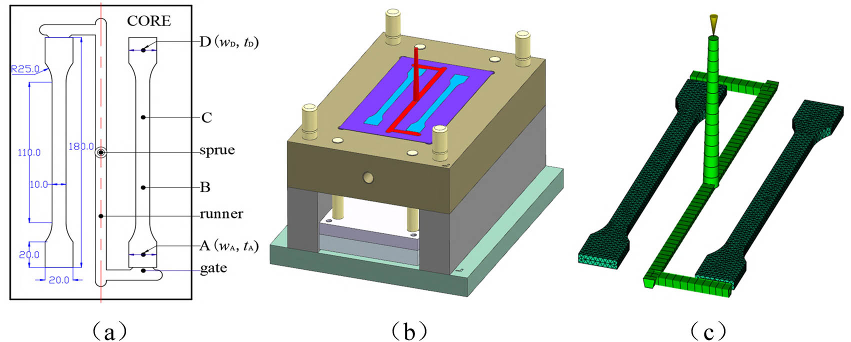
Tensile test specimen mold and finite element model. (a) Specimen dimensions and test points, (b) mold structure, (c) finite element model.
To verify the universality of the proposed method, another product with a different geometric structure was designed, as shown in Figure 2(a). It features protruding thin-walled structures on both sides and a circular hole in the middle, which undoubtedly have a significant impact on the flow behavior of the polymer melt, fundamentally differing from the simple thin-walled geometry of Figure 1(a). The tolerance ranges for the widths (w A and w D) and thicknesses (t A and t D) at both ends of this test specimen are the same as those of the product in Figure 1(a). The validation of the method using these two product cases further demonstrates the effectiveness of the proposed approach.
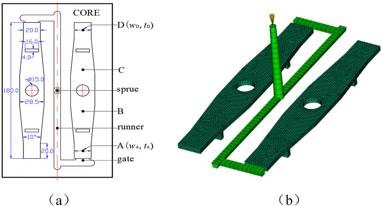
Test specimen and finite element model. (a) Specimen dimensions and test points and (b) finite element model.
This study first validated the process method using the mold flow analysis software Moldflow 2022. The product mesh type was selected as dual domain, with the global element edge lengths for the product and runner finite element meshes set to 2 and 2.5 mm, respectively. The products shown in Figures 1(a) and 2(a) achieved matching percentages of 99.06% and 98.7% through mesh statistics, with aspect ratios as low as 3.4 and 3.6, respectively, indicating exceptionally high mesh quality, as illustrated in Figures 1(c) and 2(b). The analysis sequence was “filling + packing + warping.” To investigate the effectiveness of the proposed method for different polymer materials, two materials were selected for study: Trinseo’s CALIBRE IM 401-18, with recommended mold surface and melt temperatures of 100° and 300°, respectively. The weight tolerance ranges for Figures 1(a) and 2(a) are 11.02 ± 0.06 and 13.38 ± 0.06 g, respectively. The other material was Mitsubishi Chemical's TFX 210, for which the recommended mold surface temperature is 50°C and the melt temperature is 230°C. Due to differences in material density, the weight tolerance ranges for Figures 1(a) and 2(a) were adjusted to 10.71 ± 0.06 and 12.92 ± 0.06 g, respectively.
3.2 Optimization of screw stroke and injection velocity
In Moldflow 2022, the process settings were configured as follows: fill control was set to “Absolute Screw Speed Curve”, V/P switch was set to “Screw Position”, pack control was set to “Fill Pressure vs Time”, and cooling time was set to 10 s. To investigate the complete filling process, the V/P switchover point was set at screw position x = 10 mm, with the initial injection speed set to 60 mm·s−1. The screw position x for the start of material feeding was set at 55 mm.
Through simulation experiments, the pressure at the near-gate position A and the corresponding screw position are shown in Figure 3. When the screw advanced approximately 0.57 s, the melt filled the runner and began entering the mold cavity, causing a sudden rise in cavity pressure. At this moment, the screw position x was 43.82 mm. When the screw reached x = 22.85 mm (injection time about 1.77 s), a turning point in pressure was observed, as marked “M” in Figure 3, indicating that the cavity was fully filled with polymer and the melt was under significant compression. At a screw position of x = 15 mm (injection time about 2.18 s), the polymer continued to be slowly compressed into the cavity, with the pressure peaking at 38.35 MPa. Subsequently, the screw was slightly retracted to 21.6 mm and maintained a holding pressure of 10 MPa. Therefore, the total screw displacement for complete filling (including the runner) was 55 – 15 = 40 mm, while the screw displacement for cavity filling alone was 43.82 – 15 = 28.82 mm.
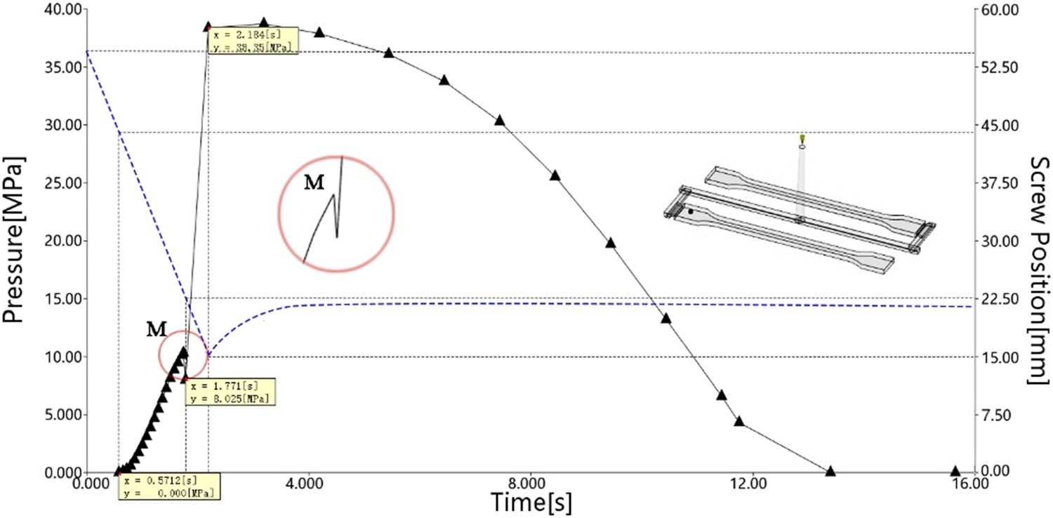
Pressure at point A vs screw position.
Injection speed significantly impacts product quality and molding cycle time. To maintain stable polymer melt viscosity and ensure smooth flow, a minimum injection speed must be set. However, excessively high speeds should also be avoided. Otherwise, it may lead to excessive pressure variations across different sections of the mold cavity, compromising dimensional accuracy or even causing shear-induced overheating, material degradation, and defects such as PVC discoloration or jetting marks. In this study, based on the aforementioned simulation results, the V/P switchover point was preset at a screw position of 22.85 mm. The injection speed was tested within a range of (60, 120) mm·s−1, incremented in 10 mm·s−1 intervals. To investigate the pressure difference (ΔP) between the near-gate (point A) and far-gate (point D) regions, pressure data were extracted at two key time points: t₁ = 4 s (screw position about 56.43 mm) and t₂ = 8 s (screw position about 41.36 mm). The resulting pressure differentials are illustrated in Figure 4.
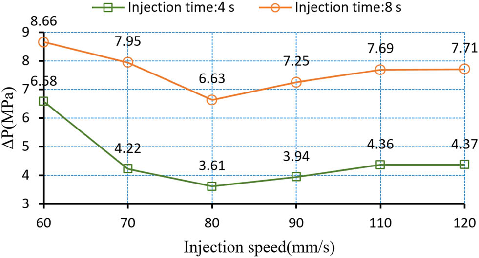
Pressure difference between near-gate and far-gate regions.
At both 4 and 8 s injection times, ΔP exhibited a consistent trend of initially decreasing, then increasing, and finally stabilizing as the injection speed increased. The minimum pressure difference between cavities A and D occurred at an injection speed of 80 mm·s−1, with ΔP measuring 3.61 MPa at 4 s and 6.63 MPa at 8 s. Polymer melt experiences heat dissipation within the mold cavity. At lower injection speeds, increased melt freeze-layer thickness significantly amplifies the pressure differential between near-gate and far-gate regions. Higher injection speeds effectively reduce this freeze-layer thickness. However, thin-wall injection molding inherently implies high flow resistance. Although excessively high injection pressure enables rapid filling, it forces the melt to flow through narrow spaces at extremely high speeds, leading to a sharp increase in polymer viscous dissipation and significant consumption of pressure energy. Simultaneously, the resistance effect is amplified exponentially, exacerbating flow imbalance. The superposition of these effects causes the pressure energy gradient to become extremely steep from the gate to the end of the product, ultimately resulting in a substantial pressure difference between different regions of the product. Based on these findings, an injection speed of 80 mm·s−1 was selected for this study.
3.3 Dynamic optimization of V/P switchover point
First, a simulation experiment was conducted on the product in Figure 1(a). In the process settings, a single-stage holding pressure was applied, with the holding pressure set at 80% of the peak injection pressure. The V/P switch was configured using “% filled volume” as the criterion, tested at 2% intervals from 85% to 99% (8 total experiments). For each trial, product weight (wt), along with width (w) and thickness (t) at points A and D, was recorded. As shown in Figure 5(a) and (b), the tolerance ranges for wt, w A, t A, w D, and t D are indicated by dashed lines. Results demonstrate that wt, w, and t increased with delayed filling volume percentage, confirming that higher cavity fill percentages before switching allow more melt to be packed into the cavity, consequently increasing all three measured parameters.
Variation trends of injection molding product indicators. (a) Weight vs filling volume percentage and (b) width and thickness vs filling volume percentage.
Figure 5(a) demonstrates that the product weight exhibits broad tolerance to V/P switchover point variations, with all experimental conditions meeting product specifications. Figure 5(b) reveals that for products with significant relative length, pressure propagation to far-gate regions becomes challenging during the holding phase, resulting in inadequate melt compensation. While the width and thickness at the far-gate (D) remain within tolerance despite delayed V/P switching, the near-gate (A) experiences melt over-compensation. Dimensions progressively deviate toward upper tolerance limits as switching is delayed. As discussed in Section 2.1, this confirms that far-gate dimensional quality is primarily controlled by V/P switchover point, whereas near-gate quality can be regulated through multi-stage holding pressure.
Using far-gate (D) width and thickness as quality targets, we identified the optimal V/P switchover position by minimizing the Euclidean distance to the origin in error space. The experimental data for w D and t D were converted to corresponding screw positions (x) based on cavity fill percentage, yielding an operational range of (27.01, 18.76) mm for 85–99% filling. Through regression analysis, we derived second-order polynomial, Eqs. 1 and 2:
The constructed w(x) and t(x) models showed statistically significant results in error analysis (p-value <0.05), with the width of the prediction confidence intervals being less than 10% of the tolerance band (0.02 mm). Their R² values reached 0.94 and 0.92, respectively. As shown in Figure 6(a), the residual distribution of the width model satisfies the assumptions of normality and homoscedasticity. The fitted value plot in Figure 6(b) further confirms the reliability of the model predictions. Similarly, the thickness model t(x) is also reliable.
Residuals vs fitted values plot of the width model. (a) Scatter plot of residuals and (b) fitted values plot.
By substituting Eqs. 5 and 6 into 3 and 4, respectively, the designed width w
design and designed thickness t
design are determined to be 20 and 4 mm. This yields the error plane Ψ(ε
w
, ε
t
). The optimal V/P switchover point screw position can be calculated using the least squares method. Through the constrained optimization function “fmincon” in MATLAB, the optimal position is obtained as

Optimal screw position solution in error plane Ψ(ε w, ε t ).
When the screw position at the V/P switchover point is 21.7 mm, the above research indicates that the product weight meets the tolerance requirements, and the dimensional quality at the far-gate area is optimal. However, as shown in Figure 5(b), when the volume filling rate at the V/P switchover point is only 85% at the beginning, the dimensions at the near-gate area A meet the requirements. As the V/P switch point is delayed, the over-compensation of the melt at area A leads to excessive dimensions, exceeding the upper limit. Consequently, there is a significant discrepancy between areas A and D of the product. The dimensional imbalance between the near-gate and far-gate areas is primarily caused by the pressure difference between the two regions during the pressure-holding phase.
As shown in Figure 8, five points were selected for pressure variation analysis. The first is the inlet of the main runner (node N2781), whose pressure change represents the pressure setting of the injection molding machine – 80% of the peak pressure, using a single-stage pressure-holding method. The remaining four points are evenly distributed from the near-gate to the far-gate areas, from node N818 to N795, corresponding to areas A, B, C, and D in Figure 1(a). From Figure 8, it can be seen that when the molding time is approximately 5 s, the pressures at the near-gate and far-gate areas are 36.7 and 33.05 MPa, respectively. The pressure difference between them remains nearly stable at around 3.65 MPa throughout most of the pressure-holding phase. Therefore, the pressure difference across different areas of the product inevitably leads to lower overall dimensional accuracy. To balance the pressure distribution in the mold cavity during the molding cycle, this study investigates multi-stage pressure holding to reduce the pressure difference.
Pressure path diagram of single-stage pressure holding.
3.4 Analysis of multi-stage pressure holding control
Compensating for shrinkage defects in the far-gate area of the mold with a higher holding pressure often leads to overfilling in the near-gate area, increasing geometric deviations in that region. To address this issue, this study proposes a multi-stage gradient pressure-holding process: first, a higher holding pressure is applied, followed by a stepwise pressure reduction to gradually release the residual cavity pressure in the near-gate area before the gate solidifies, thereby effectively reducing the residual pressure gradient between the near-gate and far-gate areas.
The specific parameters of this multi-stage pressure-holding scheme are as follows: the initial holding pressure was set at 90% of the peak injection pressure. The freezing time, which is defined as the moment when the frozen layer factor reaches 0.8, was obtained through Moldflow simulation. The freezing times for points D to A were determined as 4.22, 6.15, 8.21, and 9.38 s, respectively. The total holding duration corresponds to the freezing time of point A (9.38 s), ensuring that the holding phase concludes before gate solidification. Subsequently, the segmented holding times are calculated based on the difference in regional solidification times. Each holding segment corresponds to the time window between the solidification of adjacent regions, gradually releasing pressure before the near-gate area solidifies to avoid over-packing. The melt solidification times are 9.38, 8.21, 6.15, and 4.22 s for points A to D, respectively. Time segmentation calculation is as follows: as shown in Figure 3, the injection time was 2.18 s, and point D solidifies at 4.22 s. Thus, the packing time for stage 1 is 4.22–2.18 s = 2.04 s. Similarly, the holding times for stages 2–4 are 1.93, 2.06, and 1.17 s, respectively.
The holding pressure was then progressively reduced to 80%, 60%, and 30% in the subsequent three phases. This gradient pressure reduction strategy not only ensures molding quality near the gate region but also facilitates rapid residual stress release. For the test samples in Figures 1(a) and 2(a), the screw positions at the V/P switchover point were set at 21.7 and 20.4 mm, respectively. This corresponds to performing the V/P switch when the mold cavity volume filling rates reached 97.6% and 98%. A comparative analysis was conducted between single-stage and multi-stage pressure holding, with the results shown in Table 1. Here, SP1 and SP2 represent the test samples from Figures 1(a) and 2(a), respectively, while Mat.1 and Mat.2 denote the polymer materials Trinseo CALIBRE IM 401-18 and Mitsubishi Chemical TFX 210.
Comparison of dimensions and weight between two pressure holding methods
| Holding method | SP. | Material | w A (mm) | w D (mm) | t A (mm) | t D (mm) | Δw A–D | Δt A–D | wt (g) |
|---|---|---|---|---|---|---|---|---|---|
| Single stage | SP1 | Mat.1 | 20.18 | 20.06 | 4.17 | 4.01 | 0.12 | 0.16 | 11.06 |
| Mat.2 | 20.17 | 20.04 | 4.15 | 4.02 | 0.13 | 0.13 | 10.68 | ||
| SP2 | Mat.1 | 20.2 | 20.07 | 4.18 | 4.03 | 0.13 | 0.15 | 13.41 | |
| Mat.2 | 20.18 | 20.08 | 4.19 | 4.04 | 0.1 | 0.15 | 12.96 | ||
| Four stage | SP1 | Mat.1 | 20.06 | 20.03 | 4.04 | 3.97 | 0.03 | 0.07 | 11.03 |
| Mat.2 | 20.07 | 20.05 | 4.05 | 4.01 | 0.02 | 0.04 | 10.72 | ||
| SP2 | Mat.1 | 20.08 | 20.05 | 4.06 | 4.03 | 0.03 | 0.03 | 13.37 | |
| Mat.2 | 20.07 | 20.06 | 4.05 | 4.04 | 0.01 | 0.01 | 12.93 |
Due to the reduced melt compression effect of the four-stage holding pressure on the near-gate region A, the dimensions of region A decreased significantly compared to the far-gate region D. In the case of Figure 1(a) specimen fabricated with Trinseo CALIBRE IM 401-18 material, the width w A and thickness t A decreased to 20.06 and 4.04 mm, respectively, both meeting the product tolerance requirements. The width fluctuation decreased from 0.12 mm with single-stage holding pressure to 0.03 mm with four-stage holding pressure, a reduction of 58.3%. The thickness fluctuation decreased from 0.16 to 0.07 mm, a reduction of 56.3%. Additionally, the product weight (11.03 g) met the quality requirements and was closer to the design weight of 11.02 g. For the Figure 1(a) specimen fabricated with Mitsubishi Chemical TFX 210 material, the width w A and thickness t A decreased to 20.07 and 4.05 mm, respectively, while still fully complying with product tolerance requirements. Notably, the dimensional variation in width was reduced from 0.13 mm (single-stage packing) to 0.02 mm (four-stage packing), and thickness variation improved from 0.13 to 0.04 mm. The product weight (10.72 g) also approached closer to the design target of 10.71 g. When conducting simulation tests with both polymer materials for the Figure 2(a) specimen, Table 1 demonstrated consistent improvement patterns, effectively enhancing the dimensional accuracy of injection-molded products in both cases. These results confirmed that the optimization method proposed in this study exhibits excellent robustness.
Figure 9 shows the pressure path diagrams at the sprue entrance and regions A, B, C, and D of the product shown in Figure 1(a). The pressure-time curves for various parts of the product almost overlap, with a pressure difference of only 0.36 MPa between regions A and D. In contrast, the mold cavity pressure difference with single-stage holding pressure reached 3.65 MPa. Therefore, the four-stage holding pressure adopted in this study ensures a more uniform pressure distribution in the mold cavity, thereby improving the dimensional quality of the product.
Pressure path diagram of four-stage holding pressure.
4 Injection molding experiment validation
This article only conducts actual injection molding experiments on the product in Figure 1(a) based on its simulated injection process parameters. The injection molding machine used in the experiment was a Fanuc α-S50iB, with a maximum clamping force of 500 kN, a screw diameter of 22 mm, a maximum injection speed of 350 mm·s−1, and maximum injection and holding pressures of 290 MPa. The polymer material selected was consistent with the simulation experiment, namely Trinseo CALIBRE IM 401-18. The melt density of the material was 1.0477 g·cm−3, with a volumetric shrinkage rate of 0.5–0.7%. The mold temperature range was 80–120°C, and the melt temperature range was 280–320°C. For the injection experiment, the mold surface temperature and melt temperature were set to 100°C and 300°C, respectively. The injection mold was designed based on Figure 1(b), as shown in Figure 10(a). To validate the accuracy of the simulation experiment, two batches of actual injection molding experiments were conducted, employing single-stage and four-stage holding pressures, respectively. The holding pressures were the same as those in Sections 3.3 and 3.4, with the V/P switch point set at a screw position of 21.7 mm. The remaining injection process parameters were consistent with the simulation experiment. For each batch of experiments, injection molding trials were conducted. To ensure the stability of the injection molding machine, the first 10 molded products were discarded, and only the average dimensions of the subsequent 10 products were recorded for statistical analysis. The results are presented in Table 2. Figure 10(b) shows the injection-molded product under four-stage holding pressure.
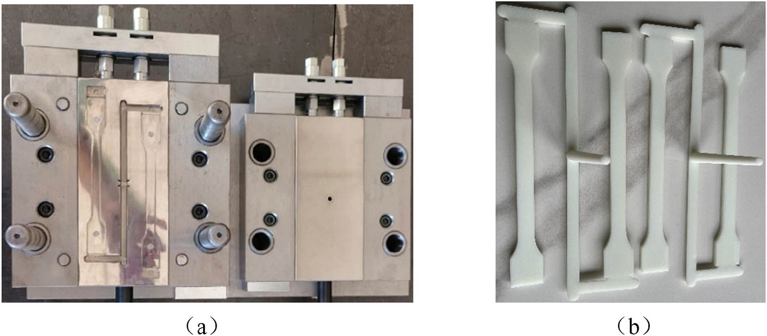
Test platform: (a) injection mold and (b) injection-molded product.
Dimensional and weight statistics of two holding pressure methods
| Holding method | w' A (mm) | w' D (mm) | t' A (mm) | t' D (mm) | Δ'w A–D | Δ't A–D | wt′ (g) | |
|---|---|---|---|---|---|---|---|---|
| Single stage | Avg. | 20.2 | 20.09 | 4.18 | 4.03 | 0.11 | 0.15 | 11.07 |
| Std. | 0.016 | 0.01 | 0.006 | 0.005 | — | — | 0.011 | |
| Four stage | Avg. | 20.07 | 20.05 | 4.05 | 4.01 | 0.02 | 0.04 | 11.05 |
| Std. | 0.015 | 0.013 | 0.005 | 0.005 | — | — | 0.013 | |
The results in Table 2 indicate that the product formed by the single-stage holding method did not meet the dimensional tolerance requirements at point A. However, when the four-stage holding method was adopted, all indicators of the injection-molded product were within the tolerance range. Under single-stage holding pressure, the average width and thickness at the near-gate region A were 20.2 and 4.18 mm, respectively, with standard deviations of 0.016 and 0.006 mm. Compared to the simulation results in Table 1, the actual injection-molded products had width and thickness errors of only 20.2 – 20.18 = 0.02 and 4.18 – 4.17 = 0.01 mm at region A. The errors for other dimensions were also within a very small range, demonstrating the high accuracy of the simulation experiment.
5 Conclusion
In the injection molding process, selecting appropriate process parameters is crucial to ensuring product quality. However, for products with a high length-to-thickness ratio, it is often challenging to achieve dimensional uniformity between the near-gate and far-gate regions after the holding pressure stage, as the injection pressure struggles to effectively transmit to the flow-end region. The geometric accuracy of the far-gate region is primarily controlled by the screw position at the V/P switchover point. Based on the width and thickness tolerance requirements of the plastic product, a three-phase dynamic optimization strategy for the V/P switchover point was proposed, and the dimensional uniformity was improved using a multi-stage holding pressure method.
This study employed a plastic tensile part with a high length-to-thickness ratio as a validation case for injection molding. Using mold flow simulation technology, the volumetric fill rate was incrementally increased from 85% to 99% in 2% steps to obtain width and thickness data for the far-gate region. A second-order polynomial regression analysis was applied to derive precise second-order functions correlating the screw position x at the V/P switch point with the width w and thickness t. Finally, the least squares method was used to determine the optimal V/P switch point screw position x = 21.7 mm, corresponding to the minimum Euclidean distance between the point (w, t) and the origin. This ensured the dimensional requirements of the far-gate region, with relative errors in width and thickness of only 0.3% and 0.5%, significantly improving the dimensional quality of the far-gate region.
To balance the pressure difference between the far-gate and near-gate regions, a four-stage holding pressure method with a gradient reduction was adopted. The holding pressures were set at 90%, 80%, 60%, and 30% of the peak injection pressure, respectively. The holding times were determined based on the freeze layer factors of the four regions from the gate to the far end, set at 2.04, 1.93, 2.06, and 1.17 s, respectively. This approach reduced the pressure difference between the near-gate and far-gate regions from 3.65 to 0.36 MPa, a decrease of 3.29 MPa. Compared to single-stage holding pressure, the four-stage method reduced width fluctuations in the near-gate region by 58.3% and thickness fluctuations by 56.3%.
Acknowledgments
This research is supported by the Special Project for Key Areas of Ordinary Colleges and Universities in Guangdong Province under Grant No. 2024ZDZX3099. This research is also supported by the 2024 Shaoguan City Research Support Program for Scientific Researchers under Grant No. 240831218038525.
-
Funding information: Authors state no funding involved.
-
Author contributions: Junhui Liu proposed the methodology of the article, designed the experimental scheme, and drafted the initial manuscript. Fuyun Li put forward constructive suggestions. Junwu Luo conducted the experimental testing and analysis.
-
Conflict of interest: The authors declare no competing interests.
-
Data availability statement: All data generated or analyzed during this study are included in this published article and its supplementary information files.
References
(1) Gim J, Turng LS. A review of current advancements in high surface quality injection molding: Measurement, influencing factors, prediction, and control. Polym Test. 2022;115:107718.10.1016/j.polymertesting.2022.107718Search in Google Scholar
(2) Chen J, Cui Y, Liu Y, Cui J. Design and parametric optimization of the injection molding process using statistical analysis and numerical simulation. Processes. 2023;11(2):414.10.3390/pr11020414Search in Google Scholar
(3) Ramesh S, Nirmala P, Ramkumar G, Sahoo S, Anitha G, Gnanasekar AK, et al. Simulation process of injection molding and optimization for automobile instrument parameter in embedded system. Adv Mater Sci Eng. 2021;1:9720297.10.1155/2021/9720297Search in Google Scholar
(4) Wang Z, Li J, Sun Z, Bo C, Gao F. Multiobjective optimization of injection molding parameters based on the GEK-MPDE method. J Polym Eng. 2023;43(9):820–31.10.1515/polyeng-2022-0236Search in Google Scholar
(5) Moayyedian M, Qazani MRC, Pourmostaghimi V. Optimized injection-molding process for thin-walled polypropylene part using genetic programming and interior point solver. Int J Adv Manuf Technol. 2023;124(1):297–313.10.1007/s00170-022-10551-2Search in Google Scholar
(6) Zhang R, Wu L, Lin X. Particle swarm optimization for multi-cavity injection molding process: A case study. Int J Adv Manuf Technol. 2021;112(5):1345–54.Search in Google Scholar
(7) Guo X, Tang Y, Xu J. Hybrid optimization algorithm for injection molding cooling system design based on PSO and SA. Polym Eng & Sci. 2020;60(3):295–304.Search in Google Scholar
(8) Yu S, Zhang T, Zhang Y, Huang Z, Gao H, Han W, et al. Intelligent setting of process parameters for injection molding based on case-based reasoning of molding features. J Intell Manuf. 2022;33:77–89.10.1007/s10845-020-01658-ySearch in Google Scholar
(9) Feng W. Integrated intelligent model for injection molding parameter optimization. Int J Adv Manuf Technol. 2021;114(3–4):987–1001.Search in Google Scholar
(10) Chen JY, Tseng CC, Huang MS. Quality indexes design for online monitoring polymer injection molding. Adv Polym Technol. 2019;2019(1):3720127.10.1155/2019/3720127Search in Google Scholar
(11) Chen JY, Yang KJ, Huang MS. Online quality monitoring of molten resin in injection molding. Int J heat Mass Transf. 2018;122:681–93.10.1016/j.ijheatmasstransfer.2018.02.019Search in Google Scholar
(12) Ageyeva T, Horváth S, Kovács JG. In-mold sensors for injection molding: On the way to industry 4.0. Sensors. 2019;19(16):3551.10.3390/s19163551Search in Google Scholar PubMed PubMed Central
(13) Nian SC, Li MH, Huang MS. Warpage control of headlight lampshades fabricated using external gas-assisted injection molding. Int J Heat Mass Transf. 2015;86:358–68.10.1016/j.ijheatmasstransfer.2015.03.027Search in Google Scholar
(14) Wang J, Mao Q. A novel process control methodology based on the PVT behavior of polymer for injection molding. Adv Polym Technol. 2013;32(S1):E474–85.10.1002/adv.21294Search in Google Scholar
(15) Nian SC, Wu CY, Huang MS. Warpage control of thin-walled injection molding using local mold temperatures. Int Commun Heat Mass Transf. 2015;61:102–10.10.1016/j.icheatmasstransfer.2014.12.008Search in Google Scholar
(16) Kitayama S, Yokoyama M, Takano M, Aiba S. Multi-objective optimization of variable packing pressure profile and process parameters in plastic injection molding for minimizing warpage and cycle time. Int J Adv Manuf Technol. 2017;92:3991–9.10.1007/s00170-017-0456-1Search in Google Scholar
(17) Chen JY, Liu CY, Huang MS. Enhancement of injection molding consistency by adjusting velocity/pressure switching time based on clam** force. Int Polym Process. 2019;34(5):564–72.10.3139/217.3867Search in Google Scholar
(18) Maeda K, Yamada K, Yamada K, Kotaki M, Nishimura H. Structure and fracture toughness of thin-wall polypropylene moulded at different injection speeds. Thin-walled Struct. 2018;125:12–20.10.1016/j.tws.2018.01.017Search in Google Scholar
(19) Nian SC, Fang YC, Huang MS. In-mold and machine sensing and feature extraction for optimized IC-tray manufacturing. Polymers. 2019;11(8):1348.10.3390/polym11081348Search in Google Scholar PubMed PubMed Central
© 2025 the author(s), published by De Gruyter
This work is licensed under the Creative Commons Attribution 4.0 International License.
Articles in the same Issue
- Research Articles
- Flow-induced fiber orientation in gas-powered projectile-assisted injection molded parts
- Research on thermal aging characteristics of silicone rubber composite materials for dry-type distribution transformers
- Kinetics of acryloyloxyethyl trimethyl ammonium chloride polymerization in aqueous solutions
- Influence of siloxane content on the material performance and functional properties of polydimethylsiloxane copolymers containing naphthalene moieties
- Enhancement effect of electron beam irradiation on acrylonitrile–butadiene–styrene (ABS) copolymers from waste electrical and electronic equipment by adding 1,3-PBO: A potential way for waste ABS reuse
- Model construction and property study of poly(ether-ether-ketone) by molecular dynamics simulation with meta-modeling methods
- Zinc–gallic acid–polylysine nanocomplexes with enhanced bactericidal activity for the treatment of bacterial keratitis
- Effect of pyrogallol compounds dosage on mechanical properties of epoxy coating
- Preparation of in situ polymerized polypyrrole-modified braided cord and its electrical conductivity investigation under varied mechanical conditions
- Hydrophobicity, UV resistance, and antioxidant properties of carnauba wax-reinforced CG bio-polymer film
- Janus nanofiber membrane films loading with bioactive calcium silicate for the promotion of burn wound healing
- Synthesis of migration-resistant antioxidant and its application in natural rubber composites
- Influence of the flow rate on the die swell for polymer micro coextrusion process
- Fatty acid filled polyaniline nanofibres with dual electrical conductivity and thermo-regulatory characteristics: Futuristic material for thermal energy storage
- Hydrolytic depolymerization of major fibrous wastes
- Performance of epoxy hexagonal boron nitrate underfill materials: Single and mixed systems
- Blend electrospinning of citronella or thyme oil-loaded polyurethane nanofibers and evaluating their release behaviors
- Efficiency of flexible shielding materials against gamma rays: Silicon rubber with different sizes of Bi2O3 and SnO
- A comprehensive approach for the production of carbon fibre-reinforced polylactic acid filaments with enhanced wear and mechanical behaviour
- Electret melt-blown nonwovens with charge stability for high-performance PM0.3 purification under extreme environmental conditions
- Study on the failure mechanism of suture CFRP T-joints under/after the low-velocity impact loading
- Experimental testing and finite element analysis of polyurethane adhesive joints under Mode I loading and degradation conditions
- Optimizing recycled PET 3D printing using Taguchi method for improved mechanical properties and dimensional precision
- Effect of stacking sequence of the hybrid composite armor on ballistic performance and damage mechanism
- Bending crack propagation and delamination damage behavior of orthogonal ply laminates under positive and negative loads
- Molecular dynamics simulation of thermodynamic properties of Al2O3-modified silicone rubber under silane coupling agent modification
- Precision injection molding method based on V/P switchover point optimization and pressure field balancing
- Heparin and zwitterion functionalized small-diameter vascular grafts for thrombogenesis prevention
- Metal-free N, S-co-doped carbon materials derived from calcined aromatic co-poly(urea-thiourea)s as efficient alkaline oxygen reduction catalysts
- Influence of stitching parameters on the tensile performance and failure mechanisms of CFRP T-joints
- Rapid Communication
- RAFT-mediated polymerization-induced self-assembly of poly(ionic liquid) block copolymers in a green solvent
- Corrigendum
- Corrigendum to “High-strength polyvinyl alcohol-based hydrogel by vermiculite and lignocellulosic nanofibrils for electronic sensing”