Influence of the flow rate on the die swell for polymer micro coextrusion process
-
Xiaozhen Deng
 ,
Zhong Ren
,
Fang Xu
,
Zhong Ren
,
Fang Xu

Abstract
A numerical model for a polymer double-layer single lumen microtubes coextrusion flow was constructed and the finite element method was used for numerical solution. The distribution of the velocity, pressure, shear rate, etc., were analyzed, as well as the relationship between the normal stress difference, secondary flow, and die swell were explored. Then, the influence of the flow velocity difference on the die swell of the double-layer microtubes was revealed. The research results indicate that, in the traditional coextrusion process, the melts will undergo expansion and deformation after leaving the die. And the velocity difference caused by the increase in the outer layer melt velocity will cause the outer layer to squeeze the inner layer, resulting in an uneven wall thickness of the composite microtubes. In the gas-assisted coextrusion process, the distribution of the velocity, pressure, shear rate, etc., can be effectively improved. However, the extrusion deformation between the melt layers caused by the velocity difference cannot be eliminated. That is, the gas-assisted technology can effectively improve the overall shape and size accuracy of composite microtubes, but cannot solve the problem of uneven wall thickness caused by the velocity difference.
1 Introduction
In the past decade, precision polymer products formed by micro extrusion have been increasingly widely used in industries such as healthcare, electronics, fine chemicals, and automobiles (1,2,3,4). The polymer micro coextrusion technology can composite the excellent properties of the different raw materials, with the characteristics of high efficiency, high quality, and low cost, etc. It expands the application range of micro section polymer products and have broad development prospects. Polymer micro coextrusion products have the characteristics of small size (such as medical interventional microtubes with an outer diameter of less than 2 mm and a wall thickness of less than 0.5 mm), complex cross-sectional shape, high geometric accuracy, and stable physical and chemical properties, which puts higher demands on micro coextrusion technology. In the traditional extrusion process, quality problems such as die swell, distortion deformation, and melt fracture, etc., are prone to occur. And the melts flow in micro coextrusion channels is more complex. Numerous studies (5,6,7,8,9,10) have shown that compared with the traditional macro extrusion, in the micro extrusion process, some factors such as wall slip, surface tension, viscoelastic rheological properties, etc., have a significant impact on micro extrusion products. And as the die size decreases, the micro extrusion product defects become more obvious and prominent due to the higher shear rates at the wall. It is difficult to produce high-performance products using traditional extrusion dies and processes. Therefore, mastering the melts flow behavior during polymer micro extrusion process, revealing the formation mechanism and influencing laws of micro extrusion forming defects, and providing theoretical guidance for the actual production process of polymer micro extrusion are key to improving the polymer micro extrusion products quality.
Many researchers have proposed corresponding solutions to the polymer micro extrusion and micro coextrusion process defects. The polymer gas-assisted extrusion technology can effectively improve the melt flow field distribution in the micro channels, and can effectively eliminate problems such as die swell and deformation. In recent years, a large amount of research has been conducted. Jin et al. (11,12) explored the extrusion process of the single lumen microtubes with a wall thickness of 0.1 mm and the five lumen microtubes with an outer diameter of 2 mm and numerically simulated the melt flow behavior inside the micro extrusion die. Based on this, they optimized the micro channel structure and conducted extrusion process experiments. The results showed that multi lumen microtubes are prone to die swell and deformation outside the die. The traditional micro extrusion die causes severe product deformation and introducing auxiliary gas inside the die can effectively reduce die swell and deformation. The gas injection volume is particularly important for the size and shape accuracy of the microtubes cross-section, directly determining the size and shape contour changes in the microtubes cross-section. Ren et al. (13,14,15,16) studied the internal and external dual gas-assisted extrusion process of the lumen microtubes with a wall thickness of 0.5 mm, and the results showed that compared with traditional extrusion process, the dual gas-assisted extrusion can significantly improve the microtubes quality. Liu et al. (17) researched the extrusion process of the single lumen microtubes with a wall thickness from 0.2 to 1.0 mm and analyzed the influence of the circular die gap characteristic scale on the viscoelastic melts extrusion swelling behavior. They found that increasing the characteristic scale reduces the swelling ratio, while increasing the melt flow rate increases the swelling ratio. Liu et al. (18) studied the extrusion process of the three lumen microtubes with a wall thickness from 0.6 to 1.4 mm and explored the polymer melt flow behavior inside the three lumen microtubes die and the extrusion swelling deformation behavior outside the die. Based on the swelling deformation law, the die shape and size were designed with reverse compensation, which significantly improved the product quality. In terms of micro extrusion technology, Zatloukal et al. (19), Liu et al. (20), and Wan et al. (21) established the relationship between process parameters and product molding quality based on the analysis of polymer melt flow behavior in micro extrusion process. Combined with process experiments, they analyzed the influencing factors of gas-assisted micro extrusion process on die swell, and revealed the influence of process parameters such as gas intake method, gas flow rate, die temperature, screw and traction speed, etc., on product quality. In summary, research on polymer gas-assisted micro extrusion process has accumulated a considerable foundation, providing a good reference for the research and development of polymer gas-assisted micro coextrusion technology. However, current research on polymer gas-assisted micro coextrusion process is still in its preliminary stage, and research on its melts flow and molding defects is far from systematic and in-depth, greatly hindering the development and application of gas-assisted micro coextrusion technology.
Researchers (22,23) conducted a study on polymer gas-assisted micro coextrusion process. The melt flow behavior for a double-layer single lumen microtubes was simulated and the influence of different gas-assisted methods on the single lumen composite microtubes process was analyzed. The results showed that gas-assisted technology can effectively eliminate the die swell and deformation phenomena. It is independent of the inlet flow rate and is easy to ensure the quality of polymer micro coextrusion products. In the double-layer single lumen microtubes coextrusion process, the internal and external gas-assisted method can effectively improve the melts flow state and enhance the composite microtubes quality. On the basis of previous research, this article intends to take a double-layer single lumen microtubes as the research object, aiming at the typical extrusion swelling problem in polymer micro coextrusion process. Based on the Phan–Thien–Tanner (PTT) viscoelastic constitutive model, the traditional coextrusion and gas-assisted coextrusion flow model of the double-layer microtubes are established. Finite element technology is used to explore the distribution of the flow velocity, pressure, shear rate, etc., revealing the influence of the secondary flow on extrusion swelling. And it will further enrich the theory of polymer micro coextrusion process and provide guidance for practical production.
2 Theoretical model
2.1 Model geometry and finite element mesh
The geometry and dimensions of the single lumen double-layer microtube are shown in Figure 1(a), where the inner and outer layers of the microtube are concentric circles with a radius difference of 0.25 mm. It is divided into two parts along the flow direction (Z-axis direction). And the flow zone inside the die and the free swelling zone outside the die are 5 and 10 mm, respectively. The model finite element meshes are shown in Figure 1(b). Due to the symmetry, 1/4 of the model is taken for simulation calculation in order to save computational resources. The meshes are appropriately densified to increase computational accuracy close to the microtube inner and outer surfaces, die inlet, die outlet, and interlayer interface, where the flow field is highly variable.

Geometry and finite element meshes of double-layer single lumen microtubes. (a) Geometry and dimensions and (b) finite element meshes.
2.2 Control equation and constitutive equation
According to the polymer melts flow behavior in microchannels, it can be assumed that the melts are an incompressible non-Newtonian fluid in a constant temperature laminar state, and the gravity and inertia forces are ignored. Therefore, the control equations can be simplified into Eqs (1) and (2).
Continuous equation:
Momentum equation:
where
The PTT constitutive equation is used to describe the melts viscoelastic flow characteristics (24,25), as shown in Eqs (3)–(5).
where
2.3 Material property parameters and boundary conditions
The microtubes inner layer is polystyrene (PS) melt and the outer layer is polypropylene (PP) melt. The melt properties and PTT parameters are shown in Table 1 (22,26,27).
Melts and PTT parameters
|
|
|
|
|
|
|
|---|---|---|---|---|---|
| PP | 4,688 | 0.15 | 0.18 | 0.30 | 0.12 |
| PS | 2,700 | 0.20 | 0.23 | 0.18 | 0.12 |
In the boundary conditions,
Inflow: Assuming that the melts at the inlet boundary are a fully developed flow, that is, satisfies the relationship,
Wall: In the double-layer single lumen microtubes coextrusion process, the melts are in contact with two wall surfaces. The melt surfaces are divided into an inner layer melt surface and an outer layer melt surface according to the inner and outer positions. A simplified Navier slip model is used to describe the relative slip between the melts and die surface. The formula is expressed as
Interface: The dynamic and kinematic conditions are satisfied,
Free surface:
Plane of symmetry:
Outflow:
2.4 Numerical calculation method
Due to the rheological properties of high viscosity and elasticity, the polymer melts constitutive characteristics have strong nonlinearity. In order to facilitate equation solving, the elastic viscous split stress combined with streamline up-winding method was used to solve the equation, and Optimesh-3D remeshing technique was used to reset the global meshes. In order to achieve final convergence of the finite element calculation, the melts relaxation time and motion boundary were set using the Evolution method, and the Galerkin method was used for iterative calculation.
3 Simulation results and analysis
3.1 Effect of flow rate difference on die swell
The area ratio of the microtubes inner and outer layer melts cross-section is 3:5. The inner layer flow rate is set to Q PS = 0.03 mm3/s, and the outer layer flow rate is set to Q PP = 0.05 mm3/s. The unit area flow rate ratio of the inner layer melt and outer layer melt is 1:1. To investigate the effect of the flow rate difference between two layers melts on the die swell of composite microtubes, five different flow rate ratios were set, namely, the inner layer PS melt flow rate was fixed at Q PS = 0.03 mm3/s, and the outer layer PP melt flow rate was set at Q PP = 0.05, 0.1, 0.15, 0.2, and 0.25 mm3/s, respectively. The flow rate ratios of the inner and outer layers were 1:1, 1:2, 1:3, 1:4, and 1:5, respectively.
The die swell rate is an important indicator for measuring the die swell phenomenon and its calculation formula is shown in Eq. (6).
where
Figure 2 shows the effect of different flow rate ratios of the inner and outer melt layers on the die swell rate of composite microtubes, and Figure 3 shows the free swell end morphology of composite microtubes in the gas-assisted micro coextrusion forming. As shown in Figure 2, in the traditional coextrusion process, the overall die swell rate of composite microtubes fluctuates around 40%. In the gas-assisted coextrusion process, the overall die swell rate of composite microtubes remains at zero, indicating no extrusion swelling phenomenon. From Figures 2 and 3, it can be seen that when the melts unit area flow rate ratio of the inner and outer layers is 1:1, the melts die swell rate of the inner and outer layers is approximately equal. However, with the increase in the outer PP melt flow rate, both traditional and gas-assisted micro coextrusion show an increase in the die swell rate of the outer PP melt, while the die swell rate of the inner PS melt decreases and even shrinks. This indicates that it forms a stable gas layer between the die inner wall and the PP melt outer surface, as well as between the die core rod outer surface and the PS melt inner surface in the gas-assisted coextrusion process, which changes the melts flow in the micro channel from a fully adhesive state to a completely sliding state. It can effectively eliminate the overall extrusion swelling phenomenon of composite micro tubes, but cannot improve the transverse flow and deformation between the melt layers caused by the flow rate difference between the inner and outer layers.
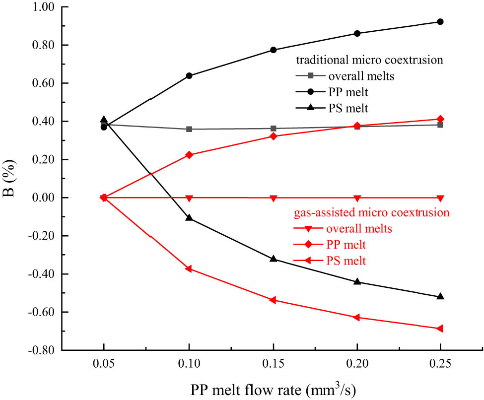
Effect of flow rate difference on die swell rate.
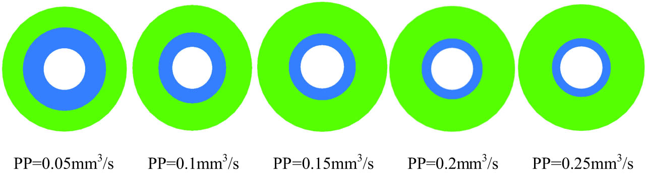
Melt swell end morphology in the gas-assisted micro coextrusion process.
To further investigate the influence of the flow velocity difference on the die swell of single lumen composite microtubes, the distribution of velocity, pressure, shear stress, normal stress difference, etc., will be analyzed.
3.2 Velocity analysis
Figure 4 shows the velocity distribution along the flow direction (Z-axis direction) on the PP outer surface, the two melts interface, and the PS inner surface. As shown in Figure 4, the melts extrusion speed increases with the increase in PP melt flow rate. In traditional coextrusion process, the melts extrusion speed increases from 0.15 to 0.5 mm/s, and in gas-assisted coextrusion process, it increases from 0.2 to 0.7 mm/s. In Figure 4, it can also be seen that in traditional coextrusion process, the flow velocity on the PP outer surface and the PS inner surface in the micro channel is relatively low, close to zero, and is independent of the change in the PP melt inlet flow rate. However, the velocity on the interlayer interface is relatively high, and increases with the increase in the PP melt inlet flow rate. This indicates that in the traditional coextrusion process, the viscous effect between the melts and the die wall or the core rod surface causes the melt to be in an incomplete sliding state, while the flow velocity at the interlayer interface is not affected by the viscous effect. The velocity difference between the inner and outer melts layers and the interfacial melts causes the melts to swell and bend after leaving the die. In the gas-assisted micro coextrusion process, when the melts unit area inlet flow ratio of the inner and outer layers is 1:1, the flow velocity on the inner and outer layer surfaces and at the interlayer interface is equal. As the unit area flow ratio increases, there is a fluctuation in the flow velocity on the inner and outer layer surfaces and at the interlayer interface at the die entrance, but it quickly stabilizes and becomes consistent. Therefore, there is no significant expansion or bending deformation of the composite microtubes as a whole. However, the flow velocity fluctuations and large flow velocity differences caused by the increase in the two flow rate ratios at the die entrance result in a deviation of the interlayer interface.
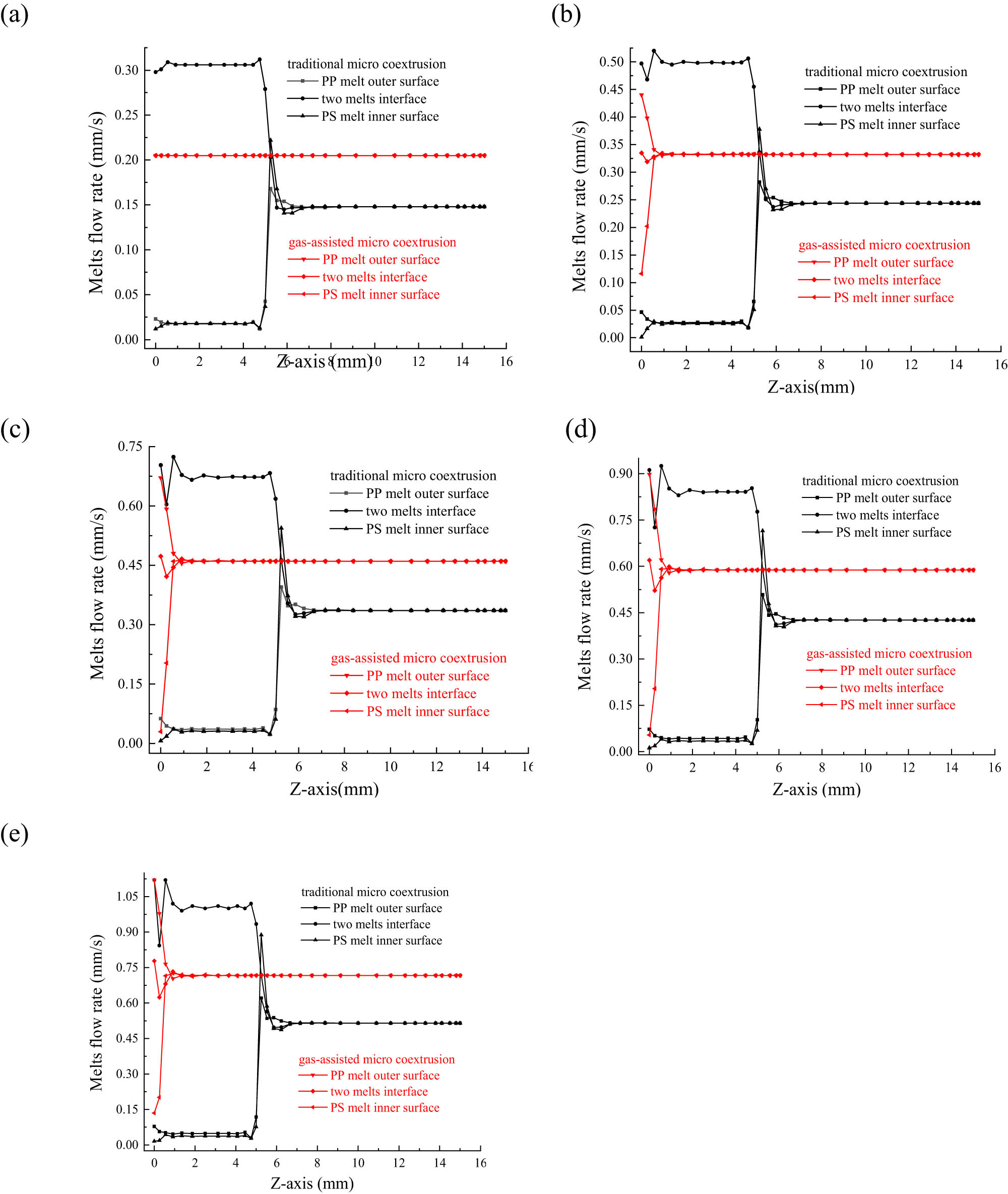
Melts velocity distribution along the flow direction. (a) Q PP = 0.05 mm3/s, (b) Q PP = 0.10 mm3/s, (c) Q PP = 0.15 mm3/s, (d) Q PP = 0.20 mm3/s, and (e) Q PP = 0.25 mm3/s.
To visually display the phenomenon of the interlayer interface displacement, the melts profile of YZ cross-section at X = 0 are taken, as shown in Figure 5. Since the melts flow has stabilized after 3 mm outside the die, the melts profiles are taken to 3 mm outside the die. From Figure 5, it can be seen that, in the traditional coextrusion process, the melts undergo deformation at both the inlet and outlet of the die. As the PP melt flow rate increases, the PP melt layer squeezes the PS melt layer inside the die, causing the PP melt layer thickness to increase while the PS melt layer thickness to shrink inside the die. At the same time, the melts undergo outward extrusion swelling deformation after leaving the die. Combined with Figure 4, the velocity difference caused by the melts incomplete slip flow state leads to two deformations at the die inlet and outlet. When the melts unit area inlet flow rate is not equal in the gas-assisted coextrusion process, there is a phenomenon of PP melt squeezing PS melt at the die inlet. This is consistent with the conclusion in Figure 4 that there is a flow rate difference at the die inlet due to the PP melt flow velocity increase. Figure 5 also shows that the melts velocity difference between the two layers is quickly improved under the gas lubrication, and the melts no longer undergoes deformation after stabilizing. There is no bending deformation or swelling phenomenon after melts leaving the die. But the deformation caused by the melts flow rate difference at the inlet cannot be eliminated. The PP layer swells and the PS layer shrinks inside the melts, that is, the displacement phenomenon of the interlayer interface of the composite microtubes cannot be eliminated.
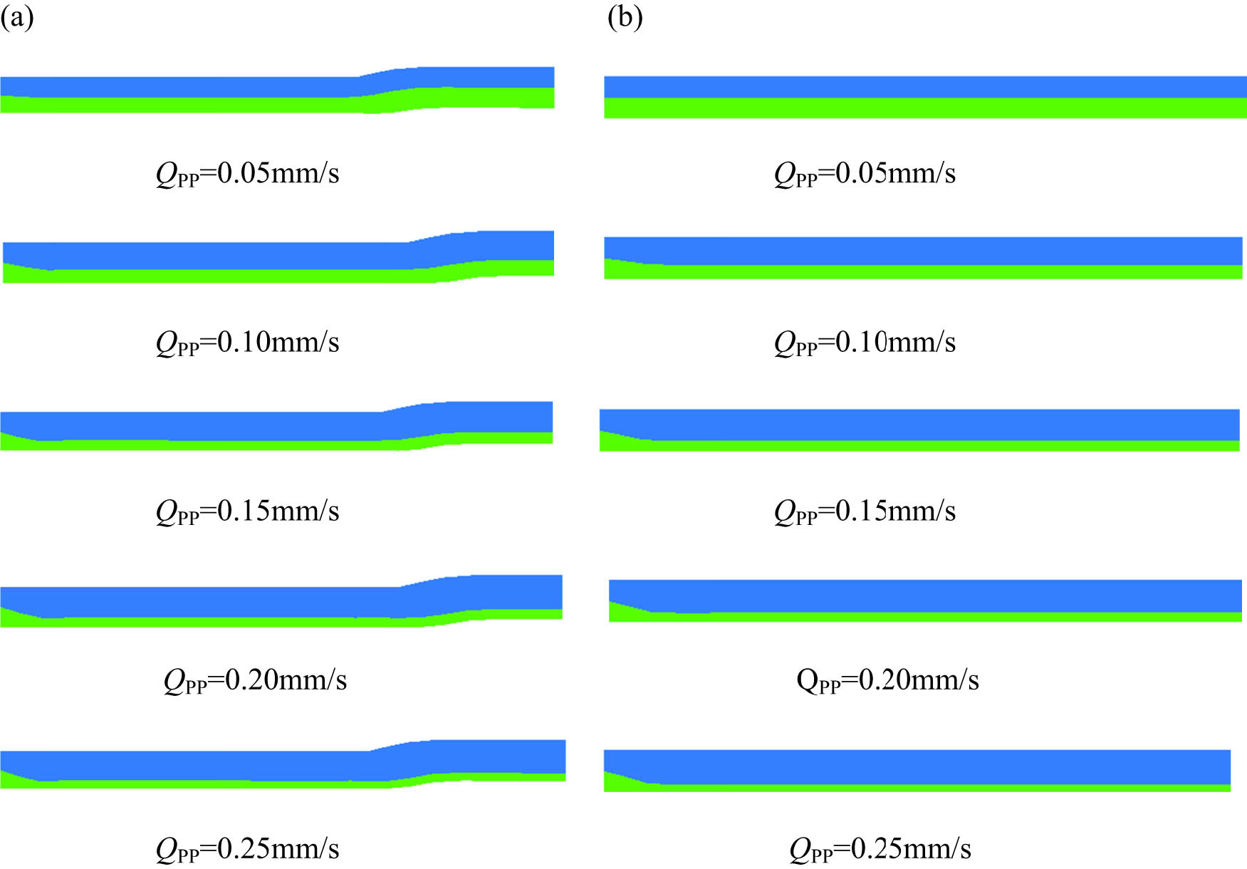
Melts profile of YZ cross-section (X = 0). (a) Traditional coextrusion process and (b) gas-assisted coextrusion process.
3.3 Die pressure drop analysis
Figure 6 shows the die pressure drop distribution along the Z-axis at the melts interlayer interface. In the research, it has been found that the die pressure drop distribution on the PP outer surface and the PS inner surface is similar to that on the interlayer interface. As shown in Figure 6, in the traditional coextrusion process, the melts pressure at the die inlet increases with the increase in PP melt flow rate, but the increase degree weakens with the increase in PP melt flow rate, and then decreases linearly to zero at the die outlet. In the gas-assisted coextrusion process, due to the lubrication effect of the stable gas layer, the melts pressure inside and outside the die is always close to zero. It indicates that the gas-assisted technology can effectively reduce the die pressure drop in polymer micro coextrusion process and is independent of the flow rate and flow velocity difference. It can effectively reduce viscous dissipation and increase the production of composite microtubes.
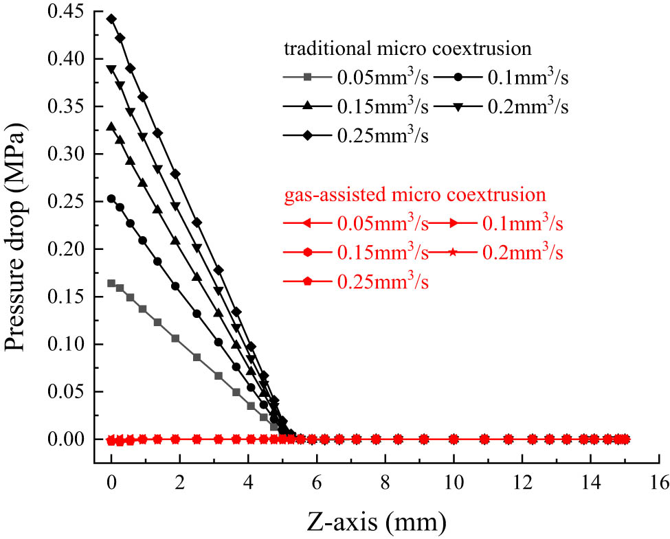
Die pressure drop distribution at the melts interlayer interface along the Z-axis.
3.4 Shear rate analysis
Figure 7 shows the distribution of the shear rate on the PP melt outer surface and the PS melt inner surface along the flow direction. As shown in the figure, in the traditional coextrusion process, there is a relatively high shear rate in the die, and there is a significant change in the shear rate at the die inlet and die outlet, especially at the die inlet, which increases with the increase in PP melt flow rate. The high shear rate and change in the die will cause the melts to undergo swelling and deformation after leaving the die. In the gas-assisted coextrusion process, there is a sudden increase in the shear rate at the die inlet with the increase in PP melt flow rate, but the value is much smaller than that of the traditional coextrusion process, and it quickly drops to zero within 0–1 mm of the die inlet and then remains stable. It indicates that the gas-assisted technology can effectively reduce the shear rate in the die and improve the distribution of the shear rate, thereby improving the die swell and deformation phenomenon of the single lumen composite microtubes.
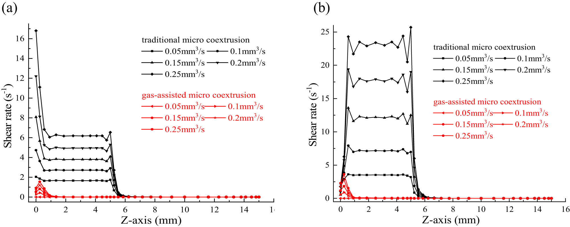
Shear rate distribution along the flow direction. (a) Shear rate on the PP melt outer surface and (b) shear rate on the PS melt inner surface.
3.5 First normal stress difference
The normal stress in the flow direction (Z-axis direction) is n 11, and the normal stress in the vertical direction (X-axis direction) is n 22. The first normal stress difference N 1 refers to the difference between n 11 and n 22, that is, N 1 = n 11 − n 22. Figure 8 shows the distribution of the first normal stress difference along the Z-axis direction on the PP melt outer surface and the PS melt inner surface.
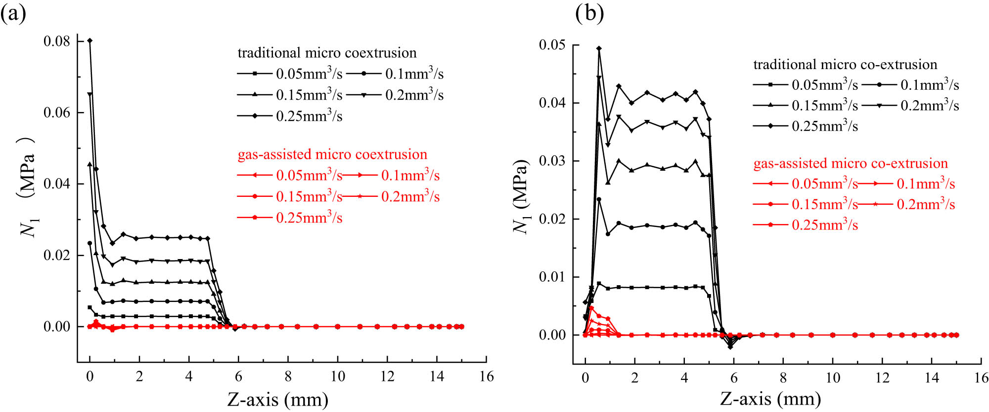
First normal stress difference distribution along the flow direction. (a) First normal stress difference on the PP melt outer surface and (b) first normal stress difference on the PS melt inner surface.
Figure 8 shows that in the traditional coextrusion process, the first normal stress difference inside the die is large, and there is a sudden change at the die inlet and outlet, which increases with the PP melt flow rate increase. The N 1 reaches zero at a distance of about 2 mm from the die end and then remains stable. The large N 1 will cause the melt molecular chains to be oriented in the flow direction and store a large amount of elastic energy. When the melt exits from the die, the elastic energy stored in the die is released; this causes the extruded material to swell and deform, severely affecting the shape and apparent quality of the extruded material. (29) In the gas-assisted coextrusion process, there is a first normal stress difference at the die inlet, which increases with the PP melt flow rate increase, but the maximum value is much smaller than that of the traditional coextrusion process. It remains stable after dropping to zero within 2 mm after the inlet, indicating that the gas-assisted technology can effectively improve the complex flow state of single lumen composite microtubes, transforming the incomplete slip flow of the melts in the die into complete slip flow. Thereby it greatly reduces the value and distribution of the first normal stress difference, and effectively improves extrusion swelling and deformation phenomena.
3.6 Melts second normal stress difference
The second normal stress difference is the difference between the normal stress in two directions perpendicular to the flow direction. In this study, the normal stress in the Y-axis direction is taken as n 33, resulting in the second normal stress difference N 2 = n 22 − n 33. Figure 9 shows the distribution of the second normal stress difference along the Z-axis direction on the PP melt outer surface and the PS melt inner surface.
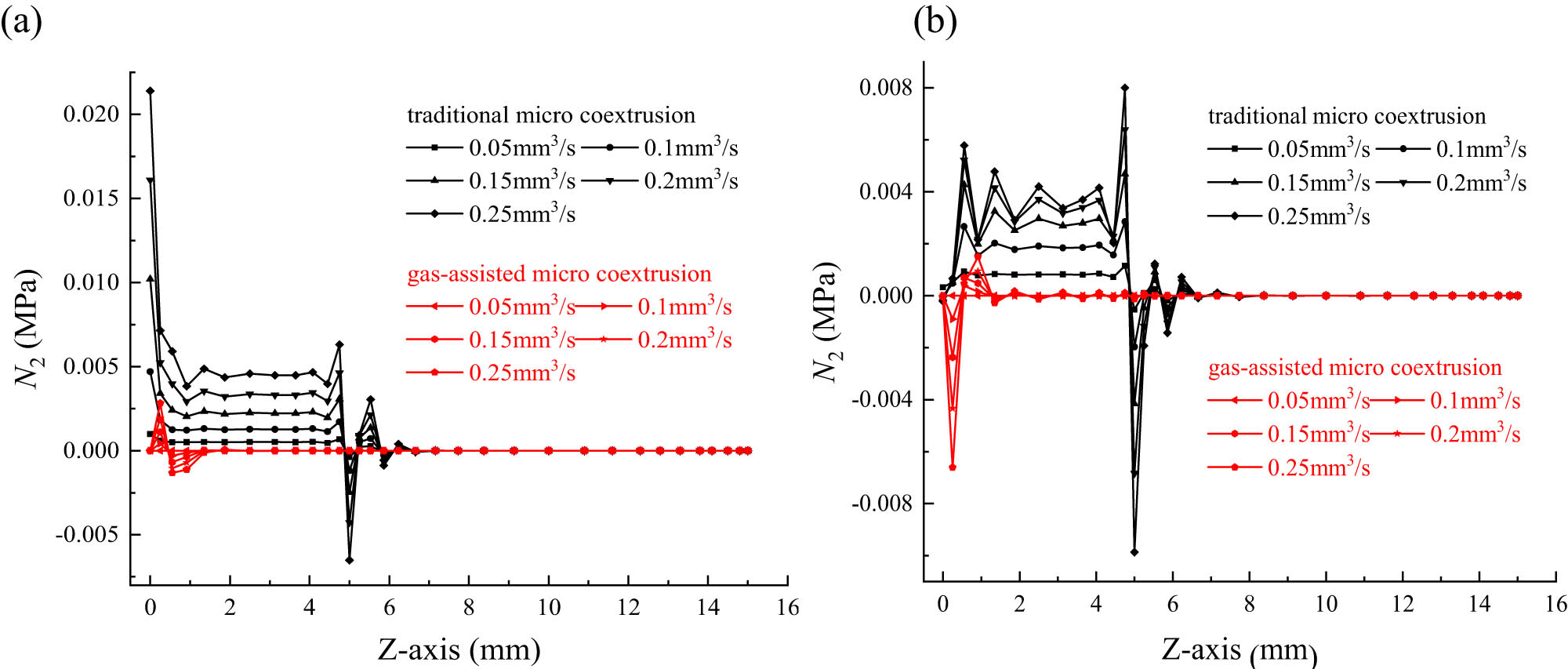
Second normal stress difference distribution along the flow direction. (a) Second normal stress difference on the PP melt outer surface and (b) second normal stress difference on the PS melt inner surface.
Yue et al. (30) found that the second normal stress difference causes a secondary flow in the viscoelastic melts flow process, and the strength of the secondary flow is proportional to the second normal stress difference. The study by Zhou et al. (31) showed that the larger the absolute value of the second normal stress difference at the die exit, the stronger the secondary flow at the coextrusion die exit, resulting in an increase in the die swell of polymer composite products with core-shell structure. As shown in Figure 9, in the traditional extrusion process of single lumen composite microtubes, the second normal stress difference on the PP and PS melts surfaces increases with the increase in PP melt flow rate. Moreover, the second normal stress difference of PP melt is relatively large within about 0–1 mm of the die inlet, while the second normal stress difference of PS melt gradually increases from a smaller value. This indicates that PP melt exerts compression on PS melt within about 0–1 mm of the die inlet, while within about 1–4 mm of the die, under the same flow rate ratio conditions, the second normal stress difference values of the two melts are relatively large and stable, indicating that there is no further compression phenomenon between the two melts within this range. The second normal stress difference of the two melts at the die outlet suddenly changed, and at a distance of about 2 mm from the die exit end, it tended to zero and then remained stable. The large second normal stress difference of the two melts in the die causes strong secondary flow, resulting in extrusion swelling of the melts after leaving the die.
In the gas-assisted coextrusion process of single lumen composite microtubes, the second normal stress difference of PP melt at the die inlet is positive, while the second normal stress difference of PS melt is negative. With about 1–2 mm distance fluctuations, it decreases to zero and then remains stable, indicating that PP melt only exerts compression on PS melt at the die entrance, then the melts flow state remains stable until it leaves the die. And the microtubes as a whole does not swell or deform. This is consistent with the conclusion in Figure 5.
4 Conclusion
In the single lumen composite microtubes coextrusion process, the flow velocity difference has a significant impact on the wall thickness, and the larger the flow velocity difference, the more obvious the impact, and the greater the difference of the wall thickness. Although the gas-assisted technology can effectively eliminate the overall swelling and deformation phenomenon of composite microtubes, its effect on improving the difference of the wall thickness caused by the flow rate difference between the two molten materials is not significant.
In the traditional coextrusion process, the flow rate of the molten material in contact with the die wall is close to zero, and the die pressure drop, shear rate, and normal stress difference inside the die are all large. Moreover, they increase with the increase in PP melt flow rate, and this will lead to an increase in viscosity dissipation during the coextrusion process. In addition, a large amount of elastic energy is stored in the die, causing molten materials radial expansion and deformation after leaving the die.
In the gas-assisted coextrusion process, the lubrication effect of the gas layer between the molten materials and the die inner wall and the core rod outer surface can effectively control the flow state and flow field distribution. The die pressure drop is close to zero, and the viscous dissipation is minimal. The flow rate only varies within 0–1 mm of the die entrance with the flow rate difference, and then remains stable, causing the molten materials to leave the die in a plunger shape. The shear rate and normal stress difference are relatively small and only change within 0–2 mm of the die entrance with the change in the flow rate difference, then tend to zero and remain stable. The molten materials are in a state of no elastic energy storage and molecular chain relaxation, so the composite microtubes have no extrusion swelling or deformation phenomenon as a whole after leaving the die.
-
Funding information: This work was financially supported by the Key Research and Development Program Project of Jiangxi Province (No. 20243BBI91011), the National Natural Science Foundation of China (No. 62165006), the Natural Science Foundation of Jiangxi Province (No. 20202BABL204025), the Open Project Fund of Key Laboratory for Optoelectronics and Communication of Jiangxi Province (No. 20202OEC001), Jiangxi Province Key Project of Natural and Science Fund (No. 20224ACB202004), and 2023 Jiangxi Province Ganpo Juncai Support Plan-High level and High skilled Leading Talent Training Project.
-
Author contributions: Xiaozhen Deng: writing – review and editing and supervision; Haibo Ji and Biao Liu: writing – original draft and synthesis; Qiang Liu: methodology and data procuration; Bing Xiao and Zhong Ren: formal analysis and project administration; Fang Xu and Li Fan: software and investigation.
-
Conflict of interest: The authors state no conflict of interest.
-
Data availability statement: All data generated or analyzed during the study are included in this published article and its supplementary files.
References
(1) Hallmark B, Mackley MR, Gadala-Maria F. Hollow microcapillary arrays in thin plastic films. Adv Eng Mater. 2006;7(6):545–7. 10.1002/adem.200400154.Search in Google Scholar
(2) Xu ZB, Xu ZY, Cao JP, Ruan XD, Chen RJ. Development and characterization of a novel polymer microchannel tube. Polym-Plast Technol. 2014;53(14):1442–9. 10.1080/03602559.2014.909480.Search in Google Scholar
(3) Stachel A, Phillips M, Rondan BR. Comparison of two methods of documenting urinary and central venous catheters at an academic medical center. Am J Infect Control. 2015;43(4):402–3. 10.1016/j.ajic.2014.12.025.Search in Google Scholar PubMed
(4) Sahmel O, Siewert S, Schmitz KP, Arbeiter D, Grabow N, Kreiner CF, Guthoff R. Extrusion as a manufacturing process for polymer micro-tubes for various bio-medical applications. Curr Dir Biomed Eng. 2019;5(1):489–91. 10.1515/cdbme-2019-0123.Search in Google Scholar
(5) Waeleghem TV, Marchesini FH, Cardon L, D’hooge DR. Melt exit flow modelling and experimental validation for fused filament fabrication: From Newtonian to non-Newtonian effects. J Manuf Process. 2022;77:138–50. 10.1016/j.jmapro.2022.03.002.Search in Google Scholar
(6) Ghnations C, Gravot E, Champaney V, Verdon N, Hascoët N, Chinesta F. Polymer extrusion die design using a data-driven autoencoders technique. Int J Mater Form. 2024;17(1):4. 10.1007/s12289-023-01796-7.Search in Google Scholar
(7) Chan WL, Fu MW, Lu J. Experimental and simulation study of deformation behavior in micro-compound extrusion process. Mater Des. 2011;32(2):525–34. 10.1016/j.matdes.2010.08.032.Search in Google Scholar
(8) Pauli L, Behr M, Elgeti S. Towards shape optimization of profile extrusion dies with respect to homogeneous die swell. J Non-Newton Fluid. 2013;200(special Sl):79–87. 10.1016/j.jnnfm.2012.12.002.Search in Google Scholar
(9) Tian HQ, Zhao DY, Wang MJ, Jin GB, Jin YF. Study on extrudate swell of polypropylene in double-lumen micro profile extrusion. J Mater Process Tech. 2015;225(0):357–68. 10.1016/j.jmatprotec.2015.06.015.Search in Google Scholar
(10) Meng LM, Wu DM, Kelly A, Woodhead M, Liu Y. Experimental investigation of the rheological behaviors of polypropylene in a capillary flow. J Appl Polym Sci. 2016;133(22):1–9. 10.1002/app.43459.Search in Google Scholar
(11) Jin GB, Wang MJ, Zhao DY, Tian HQ, Jin YF. Design and experiments of extrusion die for polypropylene five-lumen micro tube. J Mater Process Tech. 2014;214(1):50–9. 10.1016/j.jmatprotec.2013.07.016.Search in Google Scholar
(12) Jin GB, Zhao DY, Wang MJ, Jin YF, Tian HQ. Study on design and experiments of extrusion die for polypropylene single-lumen micro tubes. Microsyst Technol. 2015;21(11):2495–503. 10.1007/s00542-015-2426-6.Search in Google Scholar
(13) Ren Z, Huang XY, Xiong ZH. Experimental and numerical studies for the gas-assisted extrusion forming of polypropylene micro-tube. Int J Mater Form. 2020;13(2):235–56. 10.1007/s12289-019-01482-7.Search in Google Scholar
(14) Ren Z, Huang XY, Xiong ZH. Numerical study on the effect of gas layer width on the gas-assisted extrusion forming of plastic pipes. IOP Conf Ser: Mater Sci Eng. 2018;423(1):012033. 10.1088/1757-899X/423/1/012033.Search in Google Scholar
(15) Ren Z, Huang XY. Numerical study on the influence of gas flow rates on the gas-assisted extrusion deformation of plastic micro-tubes. J Phys: Conf Ser. 2019;1213(4):042024. 10.1088/1742-6596/1213/4/042024.Search in Google Scholar
(16) Ren Z, Huang XY. Effects of gases temperature on the viscosity and flow velocity of melt in the gas-assisted extrusion forming of plastic micro-tube. Mater Sci Forum. 2020;976(145–150):145–50. 10.4028/www.scientific.net/MSF.976.145.Search in Google Scholar
(17) Liu K, Wang MJ, Li HX, Zhao DY, Jin YF. Effect of characteristic scale on the extrudate swelling behavior of polypropylene melt in a micro-extrusion process. Polym Eng Sci. 2021;61(6):1864–81. 10.1002/pen.25707.Search in Google Scholar
(18) Liu L, Li JW, Wang XY, Liu K, Yang TY, Zhao DY. Effect of polymer three-cavity micro-tube extrusion die structure on swell deformation. Polym Mater Sci Eng. 2024;40(1):82–91. 10.16865/j.cnki.1000-7555.2024.0010.Search in Google Scholar
(19) Zatloukal M, Kopytko W, Saha P, Martyn M, Coates PD. Theoretical and experimental investigation of interfacial instability phenomena occurring during viscoelastic coextrusion. Plast Rubber Compos. 2005;34(9):403–9. 10.1179/174328905X71995.Search in Google Scholar
(20) Liu TK, Huang XY, Liu HS, Ren Z, Luo C, Wang DY. Influence of gas in the inner gas layer on gas-assisted extrusion of plastic micro-tube. Polym Mater Sci Eng. 2020;36(4):75–86. 10.16865/j.cnki.1000-7555.2020.0062.Search in Google Scholar
(21) Wan Y, Fu ZH, Zhang JX, Zang GZ, Zhang L. Simulation and experiment on extrusion molding of five-lumen medical catheter. Mater Sci Forum. 2018;923:149–55. 10.4028/www.scientific.net/MSF.923.149.Search in Google Scholar
(22) Deng XZ, Xiao B, Ren Z, Zhu ZF, Liu B. Effects of gas-assisted technology on polymer micro coextrusion. J Polym Eng. 2022;42(10):986–94. 10.1515/polyeng-2022-0013.Search in Google Scholar
(23) Deng XZ, Liu B, Xiao B, Jiang SY, Chen TR. Study on difference of single-side and double-side gas-assisted technology in polymer microtubule coextrusion molding. China Plasitcs. 2023;37(8):55–60. 10.19491/j.issn.1001-9278.2023.08.008.Search in Google Scholar
(24) Thien NP, Tanner RI. A new constitutive equation derived from network theory. J Non-Newton Fluid. 1977;2(4):353–65. 10.1016/0377-0257(77)80021-9.Search in Google Scholar
(25) Tang D, Marchesini FH, Cardon L, D’hooge DR. State of the-art for extrudate swell of molten polymers: from fundamental understanding at molecular scale toward optimal die design at final product scale. Macromol Mater Eng. 2020;305(11):1. 10.1002/mame.202000340.Search in Google Scholar
(26) Sunwoo KB, Park SJ, Lee SJ, Ahn KH, Lee SJ. Numerical simulation of three-dimensional viscoelastic flow using the open boundary condition method in coextrusion process. J Non-Newton Fluid. 2001;99(2):125–44. 10.1016/S0377-0257(01)00115-X.Search in Google Scholar
(27) Sunwoo KB, Park SJ, Lee SJ, Ahn KH, Lee SJ. Three-dimensional viscoelastic simulation of coextrusion process: comparison with experimental data. Rheol Acta. 2002;41(1-2):144–53. 10.1007/s003970200013.Search in Google Scholar
(28) Zou J, Ling ZH, Wang ZY, Jin YF, Zhao DY. Numerical simulation and analysis of the effect of compression angle on flow uniformity of double-chamber micro-tube. Mold Manuf. 2010;4:1–5. 10.13596/j.cnki.44-1542/th.2010.0072.Search in Google Scholar
(29) Mitsoulis E, Heng FL. Extrudate swell of Newtonian fluids from converging and diverging annular dies. Rheol Acta. 1987;26(5):414–7. 10.1007/BF01333841.Search in Google Scholar
(30) Yue P, Dooley J, Feng JJ. A general criterion for viscoelastic secondary flow in pipes of noncircular cross section. J Rheol. 2008;52:315–32. 10.1122/1.2817674.Search in Google Scholar
(31) Zhou WY, Zhou GF. Numerical investigation on the mechanism of polymer multilayer gas assisted coextrusion precision molding process. Acta Mater Compositae Sin. 2009;26(3):90–8. 10.13801/j.cnki.fhclxb.2009.03.003.Search in Google Scholar
© 2025 the author(s), published by De Gruyter
This work is licensed under the Creative Commons Attribution 4.0 International License.
Articles in the same Issue
- Research Articles
- Flow-induced fiber orientation in gas-powered projectile-assisted injection molded parts
- Research on thermal aging characteristics of silicone rubber composite materials for dry-type distribution transformers
- Kinetics of acryloyloxyethyl trimethyl ammonium chloride polymerization in aqueous solutions
- Influence of siloxane content on the material performance and functional properties of polydimethylsiloxane copolymers containing naphthalene moieties
- Enhancement effect of electron beam irradiation on acrylonitrile–butadiene–styrene (ABS) copolymers from waste electrical and electronic equipment by adding 1,3-PBO: A potential way for waste ABS reuse
- Model construction and property study of poly(ether-ether-ketone) by molecular dynamics simulation with meta-modeling methods
- Zinc–gallic acid–polylysine nanocomplexes with enhanced bactericidal activity for the treatment of bacterial keratitis
- Effect of pyrogallol compounds dosage on mechanical properties of epoxy coating
- Preparation of in situ polymerized polypyrrole-modified braided cord and its electrical conductivity investigation under varied mechanical conditions
- Hydrophobicity, UV resistance, and antioxidant properties of carnauba wax-reinforced CG bio-polymer film
- Janus nanofiber membrane films loading with bioactive calcium silicate for the promotion of burn wound healing
- Synthesis of migration-resistant antioxidant and its application in natural rubber composites
- Influence of the flow rate on the die swell for polymer micro coextrusion process
- Fatty acid filled polyaniline nanofibres with dual electrical conductivity and thermo-regulatory characteristics: Futuristic material for thermal energy storage
- Hydrolytic depolymerization of major fibrous wastes
- Performance of epoxy hexagonal boron nitrate underfill materials: Single and mixed systems
- Blend electrospinning of citronella or thyme oil-loaded polyurethane nanofibers and evaluating their release behaviors
- Efficiency of flexible shielding materials against gamma rays: Silicon rubber with different sizes of Bi2O3 and SnO
- A comprehensive approach for the production of carbon fibre-reinforced polylactic acid filaments with enhanced wear and mechanical behaviour
- Electret melt-blown nonwovens with charge stability for high-performance PM0.3 purification under extreme environmental conditions
- Study on the failure mechanism of suture CFRP T-joints under/after the low-velocity impact loading
- Experimental testing and finite element analysis of polyurethane adhesive joints under Mode I loading and degradation conditions
- Optimizing recycled PET 3D printing using Taguchi method for improved mechanical properties and dimensional precision
- Effect of stacking sequence of the hybrid composite armor on ballistic performance and damage mechanism
- Bending crack propagation and delamination damage behavior of orthogonal ply laminates under positive and negative loads
- Molecular dynamics simulation of thermodynamic properties of Al2O3-modified silicone rubber under silane coupling agent modification
- Precision injection molding method based on V/P switchover point optimization and pressure field balancing
- Heparin and zwitterion functionalized small-diameter vascular grafts for thrombogenesis prevention
- Metal-free N, S-co-doped carbon materials derived from calcined aromatic co-poly(urea-thiourea)s as efficient alkaline oxygen reduction catalysts
- Influence of stitching parameters on the tensile performance and failure mechanisms of CFRP T-joints
- Synthesis of PEGylated polypeptides bearing thioether pendants for injectable ROS-responsive hydrogels
- Rapid Communication
- RAFT-mediated polymerization-induced self-assembly of poly(ionic liquid) block copolymers in a green solvent
- Corrigendum
- Corrigendum to “High-strength polyvinyl alcohol-based hydrogel by vermiculite and lignocellulosic nanofibrils for electronic sensing”