Tailoring the optical and UV reflectivity of CFRP-epoxy composites: Approaches and selected results
-
Lukas Haiden
 ,
Andreas J. Brunner
,
Andreas J. Brunner

Abstract
Specific nano- and micro-scale morphologies of composites can affect the resulting optical and UV reflectivity of the materials. One example is “Vantablack®” made from aligned carbon nanotubes (CNTs) with 99.96% absorption. A similar material with CNTs grown on surface-activated aluminum (CNTs/sa-Al) even yielded 99.995% absorption, one order of magnitude higher than Vantablack®. On the other hand, fresh snow reflects 90% or more of the incident electromagnetic radiation with wavelengths between 400 and 1,000 nm. The reflectivity of snow originates from multiple scattering in the porous morphology made of snow grains. Taking these complex morphologies as inspiration, CFRP epoxy composites with different types, sizes, shapes, and amount of nanoparticles are prepared and compared regarding their optical and ultraviolet (UV) reflectivity. Increasing the reflectivity in the near and far UV may be beneficial for the durability of the epoxy composites, but selective higher or lower reflectivity in certain wavelength ranges may also yield tailored visual effects. Results from different processing approaches with selected nanoparticles are presented and discussed.
1 Introduction
Several publications describe effects of nano- or micro-scale material morphology on the reflection of electromagnetic radiation in the visible (roughly between 400 and 750 nm) and ultraviolet (UV) wavelength range (roughly between 100 and 400 nm). Extreme examples resulting in high absorption and very low reflectivity are materials with highly oriented carbon nanotubes (CNTs), on the one hand [1,2,3], and fresh snow with porosity between the flakes resulting in very high reflectivity, on the other hand [4,5]. Other examples of tuning optical properties of polymers or polymer composites are localized surface plasmon resonances (LSPR) of noble metal nanoparticles embedded in polymers [6,7,8,9]. When an incident electric field (light) with a certain wavelength hits a noble metal like Ag, Au, or Pt, the conducting electrons are oscillating in resonance. This effect results in selective photon absorption on the nanoparticle surface and different optical behaviors in the UV, visible, and IR regions. In the case of aqueous colloidal solutions of Ag nanoparticles, the color of the solution can shift from blue to red according to the size of the nanoparticles. Here, it is important to note that the surrounding medium, in our case an epoxy resin system and the distance between the particles, has an important influence on the optical properties [10,11].
Vantablack®, one of the CNT-based absorbing materials, can be applied to surfaces either via a vacuum-deposition process or as a spray coating for various technical applications, see e.g., [12,13]. The authors show that the total hemispherical reflectance of Vantablack®-treated surfaces is less than 0.45% over a wavelength range between 200 and 1,400 nm. This is due to multiple scattering of light in the “forest”-like structure of the oriented CNTs, exciting electrons that release their energy by producing phonons, thus dissipating the incident radiation into heat. More recently, a similar material has yielded even higher absorption of electromagnetic radiation, roughly a factor of 10 higher than Vantablack®. This is also made of oriented CNTs but grown on surface-activated aluminum (labelled CNTs/sa-Al). The hierarchical structure with a bimodal pore size distribution consists of the CNTs above a layer of Al nanowires. The reflectivity is 1 × 10⁻⁵ or less from the UV to the Terahertz range [3].
The mechanism yielding the high reflectivity of fresh snow is multiple scattering and deflection of incident radiation at the surfaces between snow and air pores of different sizes between the flakes. This results in the high albedo of snow [5,14]. The reflectivity amounts to 85–95% in the wavelength range between 400 and 900 nm [4]. With time, the reflectivity of snow is decreasing due to the compaction of the snowflakes, reducing and finally eliminating the porosity [15]. This yields increasing transmission in the compact snow and hence increasing absorption and less reflectivity.
These examples of snow and oriented CNT materials provide the inspiration for investigating the effects of various nano- or microparticle-modified CFRP-epoxy composites on the reflectivity of electromagnetic radiation. Being able to suitably adapt or tune the reflectivity of CFRP epoxy laminates in the visual and UV wavelength ranges or in specific, limited, wavelength bands will serve several purposes. One relates to the long-term performance of the CFRP. If a larger amount of incident UV radiation is reflected rather than being absorbed by the composite or by specific UV absorbers [16,17,18], UV-induced material degradation is expected to be slower. Another benefit of such modifications may further be the reduced heating of CFRP since less of the incident radiation is dissipated as heat, see, e.g., [19,20,21,22]. Adapting the surface reflectivity may also be beneficial for optical and telecommunication applications of CFRP, see, e.g., [2,23,24,25]. Such modifications may further allow for designing special visual effects, e.g., for CFRP on building facades, car bodies, or sports and leisure equipment, for which the use of CFRP laminates is steadily increasing. One example is Vantablack® applied on a demonstrator car body [26,27] discusses its use in artworks.
There are various processing methods for the modification of CFRP epoxy laminates: nano- and micro-scale particles can be dispersed in the epoxy matrix, deposited on the carbon fibers, or both. The particle parameters for the investigation comprise the material type of the nano- or micro-scale particles, with a range of electric properties (from electrically conducting, semiconducting to insulating), their size or size distributions, their shape, their relative orientation, but also the amount (volume fraction) and degree of dispersion in the matrix or their coverage and possibly orientation on the fibers. Combinations of different particle types, shapes, sizes, their relative fractions, and possibly suitable particle fraction gradients may also change the reflectivity behavior.
Composite laminates can be manufactured, e.g., hand lay-up and impregnation, resin infusion, resin transfer molding (RTM), or other suitable processing, such as 3D printing or similar additive manufacturing [28], again with respective effects on particle distributions and orientations.
Finally, certain types or combinations of nanoparticles dispersed in the epoxy matrix or deposited on reinforcing fibers have yielded improved mechanical properties of the composites, see, e.g., [29,30,31,32]. Therefore, the different composites with nanoparticle modifications for adapting the reflectivity can also be investigated with respect to their mechanical or thermo-mechanical performance. Hence, the research on adapting reflectivity combines several aspects of material behavior based on the same modification of CFRP laminates.
2 Materials and processing and characterization
Modification in CFRP-epoxy laminates with nano-or micro-particles is feasible in several ways. Particles can be dispersed in the epoxy matrix, deposited on the fibers before laminate processing, or as a combination of both. Each way has advantages and limitations and these are explored as follows: first, unmodified reference materials (cured epoxy resin, carbon fibers, and cured CFRP epoxy laminates) were prepared. In preliminary investigations, the focus was on modification of the epoxy resins by dispersion of nanoparticles on one hand, see, e.g., [33,34,35], and on decoration of fibers with nanoparticles via electrophoretic deposition (EPD), see, e.g., [36,37,38].
Dispersion of nanoparticles in epoxy resins for CFRP laminates manufactured by resin infusion or RTM is only feasible up to certain amounts due to changes in resin viscosity with increasing volume fractions [39,40,41]. Nanoparticles dispersed in epoxy resin may re-agglomerate at higher volume fractions or during further processing steps, e.g., after adding the hardener, see, e.g., [35,42,43] or being filtered by the reinforcing fibers in laminate manufacture via resin infusion based processes, see [44]. Such processing effects can play a significant role in defining the nano- and micro-scale morphology of the composites and hence in their reflectivity.
The epoxy resin systems used in this study were called Resin L with the associated hardener GL2 (from R&G Faserverbundwerkstoffe, Germany) and System 3 (from bto-epoxy GmbH, Austria). Both were mixed according to the producers’ recommendations in their respective ratio of 100:30 resin to hardener each. The Resin L epoxy system was chosen as matrix material for its optical high transparent behavior in the visible range, and System 3 for its good performance in RTM processing. For matrix modification, nanoparticles were dispersed into the resin via using a DISPERMAT® Dissolver with the vacuum-dispersion system CDS (both VMA Getzmann GmbH, Germany) applying 2,000 rpm for 20 min. SiO2 and Ag nanoparticles (from Sigma Aldrich) were chosen for modifying the optical properties of the CFRP matrix. In addition, single-wall CNTs, SiO2, and carbon dust, which occurs as a by-product during production, were chosen to modify the System 3 epoxy.
SiO2 nanoparticles were chosen because of their commercial availability, their spherical geometry, and their high uniformity in size. They scatter incoming light diffusely in every direction, which results in their white appearance and high reflectivity, while Ag nanoparticles were selected to investigate possible plasmonic effects. The manufacturer information about the nanoparticle size was 5–20 nm for SiO2 and below 100 nm for Ag nanoparticles, respectively. The actual size, however, was investigated using transmission electron microscopy (TEM) with a JEM-2100F (JEOL, Japan), because it was expected that the nanoparticles would tend to agglomerate. For this purpose, 1 g of each of the investigated nanoparticles was sonicated in 100 ml of deionized water for 40 min. Afterwards, 5 ml of this suspension was mixed into 90 ml of ethanol and again sonicated. Then, a drop of the resulting suspension was placed on a TEM grid (carbon-coated Cu grid), mounted on a holder, and dried under ambient conditions for 4 h prior to the investigation. Figure 1a shows TEM images of single Ag nanoparticles and clustered Ag nanoparticles in Figure 1b, while the size distribution is shown in Figure 3a. It shows rather small primary particles according to their size, but the TEM pictures revealed a high tendency for clustering. The TEM images of SiO2 primary nanoparticles are depicted in Figure 2a and their overall measured sizes in Figure 3b. They have a wider size distribution compared to Ag and are likely to agglomerate also in high numbers with a diameter of above 1 µm (Figure 2b).

Selected TEM images for verifying Ag particle size via (a) high magnification for particles stacked on top of each other and (b) overview picture using lower magnification for particle size statistics.

Selected TEM images for verifying SiO2 particle size via (a) high magnification assessing small particle agglomerations (b) overview picture using lower magnification for particle size statistics.
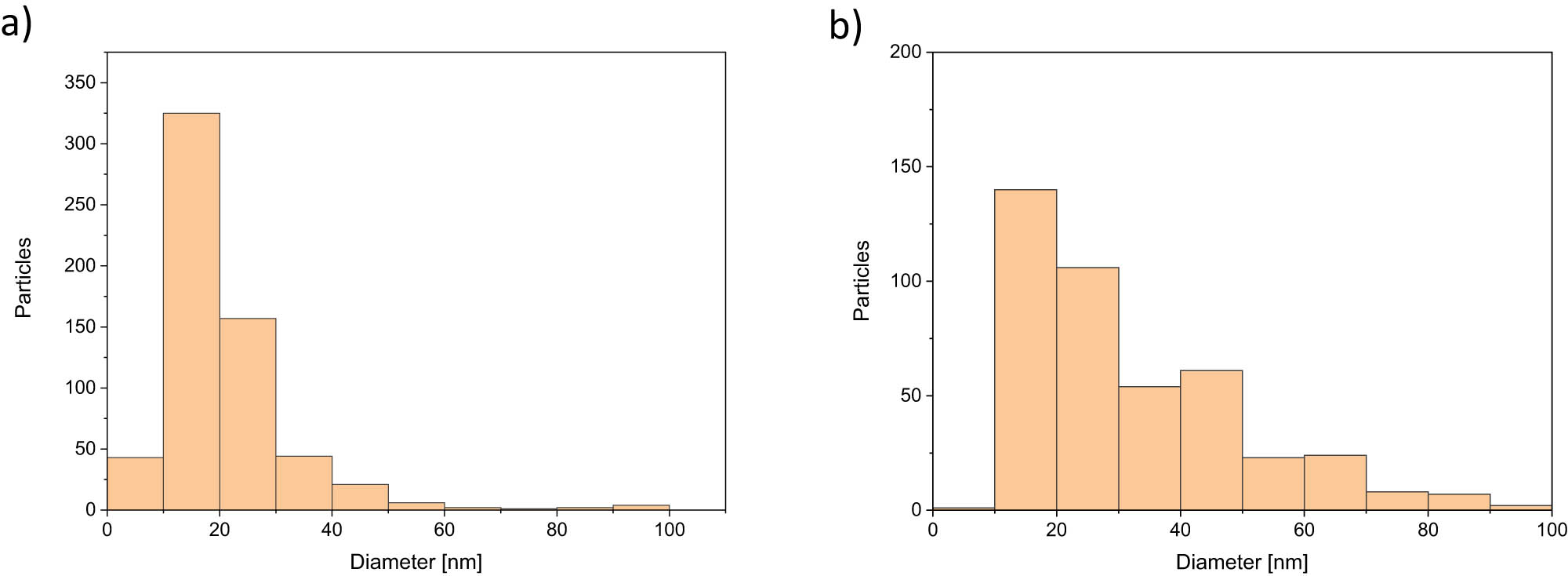
Quantitative analysis of the different particle sizes investigated during several TEM measurements for (a) Ag nanoparticles and (b) SiO2 nanoparticles.
It was expected that the size of the nanoparticles and their agglomerates, respectively, will be in accordance with particle size distributions represented in Figure 3. Afterwards, the individual-modified epoxy resin systems were cured for 15 h at 70°C.
SiO2, single-wall CNTs, and carbon dust were incorporated in the bto-Epoxy System. SiO2 again should resemble snow pores [4,5], while the CNTs and the carbon dust were chosen for producing a rather low overall reflectivity [1,2,3]. Here, the filler concentrations were 1% CNTs, 5% carbon dust and 10% SiO2. These fillers were mixed inside using the vacuum-dispersion system CDS (VMA Getzmann GmbH, Germany) utilizing 2,000 rpm for 60 min. After that homogenization step, the modified resins were used in an RTM process for laminating carbon and glass fibers. Hereby, the resin was heated to 80°C and consequently added to the carbon fabrics using 10 bar (equals 1 MPa) pressure. This was followed by a precuring step where the laminate was held at 80°C for 30 min and afterwards cured at 140°C for 3 h.
Since CFRP laminates for structural applications typically have fiber volume contents of 50% or higher, the nano- and micro-scale modification of carbon fibers by EPD was chosen as a pre-manufacturing process. This provides the possibility of eliminating the potential problems of dispersion or agglomeration of nanoparticles in the epoxy matrix and nanoparticle filtration during lamination. Quasi-static EPD fiber decoration was performed using a custom-made electrophoretic cell (see Figure 4) consisting of one metal and one dielectric plate mounted at a distance of 7 mm from each other. Carbon fibers were wound around the dielectric plate and electric junctions were added for providing the desired electric potential directly between the carbon fibers and the metal plate. The carbon fiber used for the experiments was unsized AS4 HexTow® 12k fibers delivered from Hexcel composites SA (France). Raman and thermogravimetric analysis measurements confirmed that no sizing is present. The described set-up was used for dipping the fiber lay-up into water-based suspensions with a fixed concentration of 1% nanoparticles (Ag, SiO2) while applying DC voltages from 6 to 60 V for durations of 1–15 min.

Schematic drawing of a custom-made cell used for electrophoretic deposition of nanoparticles onto carbon fibers.
After the deposition process, all coated fibers were laminated using the Resin L epoxy system. For that purpose, the modified carbon fibers were immersed into the prepared virgin epoxy resin system for 2 min while applying a vacuum of 150 mbar. After this procedure, the resin-soaked carbon fibers were put inside a vacuum bag, which was sealed with rubber tape. Furthermore, the plastic bag was evacuated, and the laminated carbon fibers were precured at a heating plate at 55°C for 300 min. As a next step, the plastic bag was disconnected from the vacuum pump and placed in an oven for further 900 min at 70°C for fully curing the resin. For the preparation of optical investigations, the test specimens were cut out of the vacuum bag and the remaining unwanted resin was removed.
In addition, Aquacyl® Multi Wall Carbon Nanotubes (purchased from Nanocyl, Belgium) were deposited using a quasi-continuous electrophoretic cell on the carbon fibers using 3 and 5 V during a deposition time of 3 min, respectively. During the deposition, the carbon fibers were pulled by a rotating plate, with a velocity that defined the chosen deposition time, through the nanoparticle suspension and wound on the plate. Afterwards, the nano-modified fibers were laminated using RTM (10 bar equals 1 MPa) and the before-mentioned modified vacuum bag process at Empa, Dübendorf. Afterwards, the laminates were precured at 55°C for 300 min and fully cured at 70°C for 900 min in both cases.
For the evaluation of the nanoparticle coverage of the fibers, they were dried after the electrophoretic deposition for several hours at 60°C and checked as such via the scanning electron microscope (SEM). The investigation of the SiO2-modified samples was carried out using 5 kV acceleration voltage due to the introduced electrical charge of the non-conductive nanoparticles, while for Ag-modified samples, an acceleration voltage of 10 or 15 kV was preferred for better resolution.
In a final step, hemispherical reflection and hemispherical transmission of all prepared samples were measured using a Lambda 950 UV/Vis spectrometer (PerkinElmer, USA) at the Polymer Competence Center, Leoben.
3 Results and discussion
3.1 Overview
In the following sections, selected results will be presented regarding the change in optical reflectivity resulting from material modifications. In the first part, the influence of matrix modifications will be shown for neat and modified System 3 and Resin L. The first one was used for laminate production via the RTM process, while for the second the changes before laminate production are presented. Furthermore, selected fiber modifications using EPD and their influence on the optical reflectivity are visualized. In this case, the modified vacuum-assisted resin infusion process (VARI) was implemented for preparing the laminates. In a final section, the influence of the chosen laminate manufacturing procedures will be compared.
3.2 Selected matrix modifications
Figure 5a shows the results of the reflection measurements for the reference materials namely the epoxy resin system 3, the glass fiber reinforcement, and further the reference laminate made from it. The glass fibers yield very high reflection values over almost the entire visible wavelength range with a significant drop in reflectivity at around 400 nm. The reflectivity of the neat resin and of the reference glass fiber laminate is almost constant at low values over the complete measured range. This investigation leads to the assumption that in the case of epoxy resin system 3, the matrix material and not the fibers are more vital in modifying the optical appearance of the laminates. For this reason, the matrix was subsequently modified with nanoparticles, prior to the laminate manufacturing. It was desired to achieve the highest possible degree of filling of the matrix system while, at the same time, taking into account the sharply increasing viscosity with regard to the RTM process. In the case of carbon dust and SiO2, filling levels of 5 and 10 wt% were selected. The degree of filling with regard to CNTs was determined by the availability of the nanoparticles and set at 1 wt%.

(a) Reflectivity of unmodified reference samples. (b) Reflectivity of glass fiber laminates with three different matrix modifications (system 3).
Consequently, Figure 5b shows the results for the nano-modified laminates. Here, the laminates that are modified via 10 wt% SiO2 reach almost the reflectivity values of the glass fiber, while the laminates that are modified with the CNTs or the carbon dust become even less reflective. In the UV range, the optical behavior of all modified laminates becomes similar to the reference laminate again. Interestingly, the different morphologies of the carbon dust and the CNTs are not of high significance regarding their optical behavior in the laminate. Likely, this is due to the fact that the CNTs are not in any ordered state, but rather randomly oriented compared to the case of VANTABLACK®, resulting in significantly lower absorption.
Figure 6 shows the results of the reflection measurements for the laminate reference using carbon fiber and the laminates with modified matrix, respectively. In this case, again the reflectivity is increasing using SiO2 and is decreasing using the CNTs as well as the carbon dust. Compared with the reference laminate, the reduction in reflectivity due to the matrix modification by carbon dust and CNTs, respectively, is slightly higher than for the respective glass fiber laminates (see Figure 5b). However, for the SiO2 matrix modification, the carbon fibers have a higher impact on reflectivity, since the values are not increasing as much as in the case of glass fibers and stay below 16%.

Reflectivity of carbon fiber composite laminates with modified matrix (system 3) using CNTs, carbon dust, and SiO2 nanoparticles compared to unmodified composite laminates.
For further investigations, the resin system was changed to Resin L (R&G Faserverbundwerkstoffe, Germany). Figure 7a and b shows the reflectivity and transmittance measurements of the unmodified epoxy resin system L. A stable reflectivity and transmittance in the visible range from 780 to 380 nm was observed. However, at 370 nm, a tremendous decrease in transmittance was found. Furthermore, a decrease in reflectivity is starting at 460 nm. Here, the optical characteristics are changing in the direction of a strongly absorbing behavior. At 305 nm, the reflectivity is starting to increase again, while the transmittance is reaching 0%. Furthermore, a difference was found between the top and bottom surface of the test specimen, with the bottom surface showing a higher reflection value in the UV range. This is possibly caused by the release agent that was applied on the mold in contact with the bottom surface of the epoxy specimen.
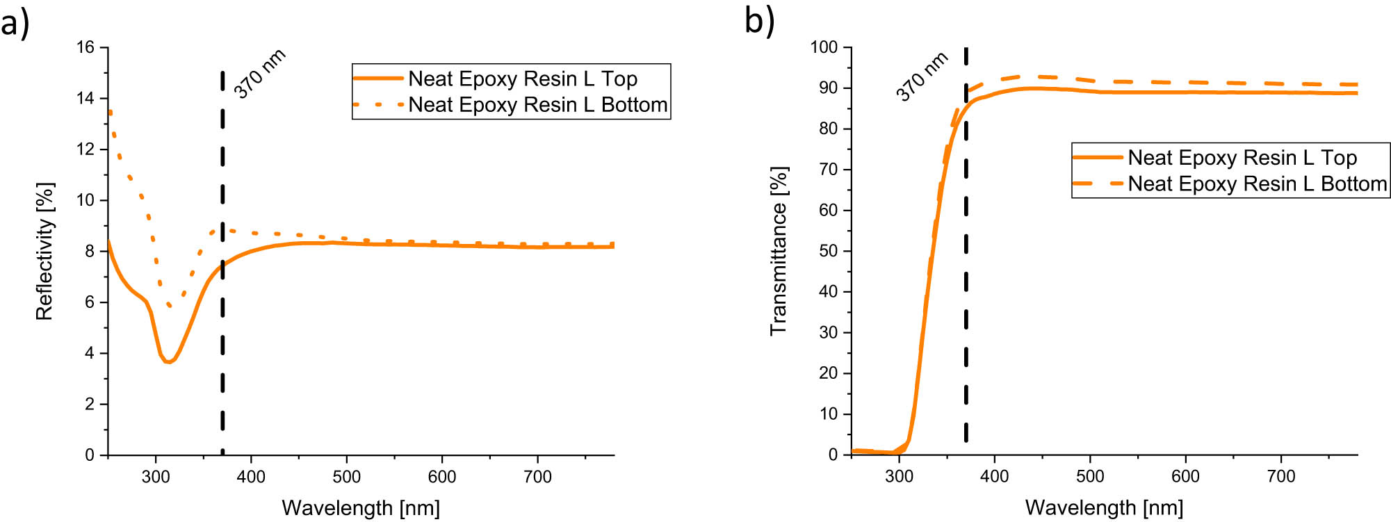
(a) Reflectivity and (b) transmittance of unmodified Resin L.
In Figure 8, the investigated reflectivity spectra for the nanoparticle-modified epoxy resin L matrix material and pictures of the measured samples are shown. In Figure 8a, the influence of SiO2 nanoparticles is depicted. Here, an increasing reflectivity is shown according to an increasing amount (wt%) of nanoparticles. With increasing nanoparticle content with different agglomerates in size within the epoxy resin, the number of potential diffuse scatter centers also increases. These subsequently lead to a macroscopic white reflection behavior of the resin with higher nanoparticle quantity. In the case of Ag nanoparticles (Figure 8c), there is a slight decrease in reflectivity with an increasing amount of nanoparticle content. The size of the nanoparticle could indicate a plasmonic behavior. However, there is a high number of agglomerations detectable even before mixing the particles inside the resin. One possible explanation could be that the particle–particle distance is too small and the LSPR is not necessarily applicable in this case. The absorption range widens (see Figure 8c) due to agglomerations, which causes the lower reflection in the measured wavelength range. Figure 8b is showing the nano-modified samples compared to the neat resin for the case of SiO2 matrix modification, while Figure 8d is showing the samples in the case of using Ag nanoparticles.

Comparison of UV/VIS reflectivity measurement results of neat Resin L and nanoparticle-modifed samples using different (a) SiO2 and (c) Ag nanoparticle contents and visual appearance (photographs) of neat and modified Resin L samples with increasing (b) SiO2 and (d) Ag nanoparticle content (neat resin L sample in upper left corner, 0.5 wt% nanoparticles in upper right corner, 1 wt% nanoparticles in lower left corner, and 5 wt% nanoparticles in lower right corner). The samples have a diameter of 9 cm and a thickness of 3 mm.
3.3 Selected fiber modifications
3.3.1 Reference materials
Figure 9 shows the reflectivity measurements of the reference materials, namely the unsized carbon fiber (AS4), the Resin L epoxy system, and the reflectivity curve of the respective composite laminate. Hereby, two layers of carbon fibers were manually wound around a PTFE plate and laminated afterward. Fiber orientation also caused differences in the outcome of the reflectivity measurements. If the fibers are mounted horizontally, the reflectivity values show up to 2% higher reflection values compared to the vertically mounted fiber orientation. At the transition from visible to the UV range at 370 nm, the reflectivity of the carbon fiber starts to increase, while the reflectivity of the resin starts to decrease. Nevertheless, for the laminate, the reflectivity stays almost constant at roughly 8% over the whole measurement range.

Reflectivity measurements of referenece materials (Hexcel 12k AS4 carbon fiber, neat epoxy Resin L, and manufactured laminate).
3.3.2 SiO2-modified CFRP
The results before and after the modified VARI lamination process is depicted in Figure 10. It is important to note that the fiber orientation has an influence on the outcome of the reflectivity values also. The reflectivity in the visible range in the case of 60 V deposition voltage is increasing at 400 nm compared to the unmodified carbon fibers (AS4), if using 1 min deposition time (Figure 10a). SEM pictures after deposition are shown in Figures 11 and 12. One minute deposition time already provides a high degree of coverage of the SiO2 nanoparticles on the fibers (Figure 11). If the time is increased to 15 min, the fibers are covered completely with the nanoparticles forming a film-like structure on the surface that connects several fibers (Figure 12). During the electrophoretic deposition, the initially white SiO2 nanoparticle suspension is turning dark grey, leading to the assumption that the carbon fibers are damaged during EPD at such high DC voltages. This could be also the reason why the reflectivity as such is decreasing while using higher deposition times. Nevertheless, after laminate manufacturing, a loss of particles was observed which led to decreased reflectivity values mainly in the UV range compared to the non-laminated state (see Figure 10b).

SiO2 fiber modification via EPD (a) before and (b) after the lamination process.

SiO2-modified carbon fibers using 60 V and 1 min.
SiO2-modified carbon fibers using 60 V and 15 min.
3.3.3 Ag-modified CFRP
The results for Ag nanoparticle-modified carbon fibers (AS4) are presented in Figure 13a. In this case, a slight increase in reflectivity for lower deposition voltages as well as deposition times is observed. If both are increased, the reflectivity starts to decrease. This again might be due to the fiber damage at higher voltages and simultaneously higher deposition times. Higher deposition time would be expected to yield a higher coverage of the carbon fibers, which could cause a higher overall reflectivity (see Figures 14 and 15). Anyhow, this effect is apparent, likely because of the fiber damage. During laminate manufacturing, a loss of particles was observed, which led to decreased reflectivity values after the lamination (see Figure 13b). After investigation via SEM, an increase in particle coverage of the carbon fibers is observed, after increasing the voltage from 6 to 30 V as well as altering the deposition time from 1 to 10 min. Furthermore, it can be seen that the particle clusters themselves become larger with increased electrical voltage and time.

Ag fiber modification via EPD (a) before and (b) after lamination.

Ag-modified carbon fibers using 6 V and 1 min.

Ag-modified carbon fibers using 30 V and 10 min.
3.3.4 Influence of manufacturing after fiber modification
Different manufacturing processes were used for lamination after depositing CNTs on the unsized AS4 carbon fiber. The results are shown in Figure 16. The overall reflectivity of the nano-modified laminates using the Resin L epoxy system is decreasing as expected compared to an unmodified laminate that was produced via the RTM process routine. It was also shown that the reflection gradually decreases for both process routes and the applied voltage during EPD influences the deposition rate of the particles.

Comparison between variations in the manufucturing processes RTM and VARI after depositing CNTs on the AS4 carbon fiber.
4 Summary and conclusions
During this work, it was proven that mainly with matrix modification and the right choice of the fiber as well as the filler the optical and UV reflectivity could be made to rise or decrease to desired values. Fiber modification via electrophoretic deposition performed for the same purpose needs to be investigated further to achieve desired levels of optical characteristics. Also, changing the deposition process to physical vapor deposition or chemical vapor deposition seems promising for future research. It becomes clear that fiber orientations, at least for unidirectional fiber lay-ups measured with fibers aligned horizontally and vertically, respectively, have a certain impact on the outcome of the optical behavior, while the lamination process itself seems to have less influence.
Acknowledgments
We gratefully acknowledge the Montanuniversität Leoben for funding this project, Hexcel for providing unsized carbon fibers type AS4, the Swiss Federal Laboratories for Materials Science and Technology for supporting this project, and Stefan Neunkirchen for guidance during the lamination processes.
-
Conflict of interest: Authors state no conflict of interest.
-
Data availability statement: The data that support the findings of this study are available from the corresponding author upon reasonable request.
References
[1] Surrey Nanosystems [Internet]. About Vantablack; c2022 [cited 2022 April 1]. https://www.surreynanosystems.com/about/vantablack.Search in Google Scholar
[2] Hammar A, Christensen OM, Park W, Pak S, Emrich A, Stake J. Stray light suppression of a compact off-axis telescope for a satellite-borne instrument for atmospheric research. In Optical Design and Testing VIII. SPIE; 2018. 2018. p. 15. https://www.spiedigitallibrary.org/conference-proceedings-of-spie/10815/2500555/Stray-light-suppression-of-a-compact-off-axis-telescope-for/10.1117/12.2500555.full.10.1117/12.2500555Search in Google Scholar
[3] Cui K, Wardle BL. Breakdown of native oxide enables multifunctional, free-form carbon nanotube-metal hierarchical architectures. ACS Appl Mater Interfaces. 2019;11(38):35212–20.10.1021/acsami.9b08290Search in Google Scholar PubMed
[4] Perovich DK. Light reflection and transmission by a temperate snow cover. J Glaciol. 2007;53(181):201–10.10.3189/172756507782202919Search in Google Scholar
[5] Meng J, Papas M, Habel R, Dachsbacher C, Marschner S, Gross M, et al. Multi-scale modeling and rendering of granular materials. ACM Trans Graph. 2015;34(4):1–13.10.1145/2766949Search in Google Scholar
[6] Fan G, Shi G, Ren H, Liu Y, Fan R. Graphene/polyphenylene sulfide composites for tailorable negative permittivity media by plasmonic oscillation. Mater Lett. 2019;257:126683.10.1016/j.matlet.2019.126683Search in Google Scholar
[7] Khan AU, Guo Y, Chen X, Liu G. Spectral-selective plasmonic polymer nanocomposites across the visible and near-infrared. ACS Nano. 2019;13(4):4255–66.10.1021/acsnano.8b09386Search in Google Scholar PubMed
[8] Aziz SB, Brza MA, Nofal MM, Abdulwahid RT, Hussen SA, Hussein AM, et al. A comprehensive review on optical properties of polymer electrolytes and composites. Materials (Basel). 2020;13(17):3675.10.3390/ma13173675Search in Google Scholar PubMed PubMed Central
[9] Satulu V, Mitu B, Ion V, Marascu V, Matei E, Stancu C, et al. Combining fluorinated polymers with Ag nanoparticles as a route to enhance optical properties of composite materials. Polymers (Basel). 2020;12(8):1640.10.3390/polym12081640Search in Google Scholar PubMed PubMed Central
[10] Hutter E, Fendler JH. Exploitation of localized surface plasmon resonance. Adv Mater. 2004;16(19):1685–706.10.1002/adma.200400271Search in Google Scholar
[11] Badi’ah HI, Seedeh F, Supriyanto G, Zaidan AH. Synthesis of silver nanoparticles and the development in analysis method. IOP Conf Ser Earth Environ Sci. 2018;217:12005.10.1088/1755-1315/217/1/012005Search in Google Scholar
[12] Adams A, Nicol F, McHugh S, Moore J, Matis G, Amparan GA. Vantablack properties in commercial thermal infrared imaging systems. In Infrared Imaging Systems: Design, Analysis, Modeling, and Testing XXX. Bellingham, WA, USA: SPIE; 2019. vol. 2019. p. 28. https://www.spiedigitallibrary.org/conference-proceedings-of-spie/11001/2518768/Vantablack-properties-in-commercial-thermal-infrared-imaging-systems/10.1117/12.2518768.full.10.1117/12.2518768Search in Google Scholar
[13] Velpula PK, Kramer D, Ďurák M, Rus B. Femtosecond laser damage resistance of beam dump materials for high-peak power laser systems. Opt Eng. 2020;59(5):1.10.1117/1.OE.59.5.056108Search in Google Scholar
[14] Haussener S, Gergely M, Schneebeli M, Steinfeld A. Determination of the macroscopic optical properties of snow based on exact morphology and direct pore-level heat transfer modeling. J Geophys Res. 2012;117(F03009):1–20.10.1029/2012JF002332Search in Google Scholar
[15] Löwe H, Spiegel JK, Schneebeli M. Interfacial and structural relaxations of snow under isothermal conditions. J Glaciol. 2011;57(203):499–510.10.3189/002214311796905569Search in Google Scholar
[16] Yousif E, Haddad R. Photodegradation and photostabilization of polymers, especially polystyrene: review. Springerplus. 2013;2:398.10.1186/2193-1801-2-398Search in Google Scholar PubMed PubMed Central
[17] Marturano V, Ambrogi V, Cota I, Cerruti P. 8 Biobased functional additives for polymers. In: Marturano V, Ambrogi V, Cerruti P, editors. Sustainability of polymeric materials. Berlin, Germany: De Gruyter; 2020. p. 173–92.10.1515/9783110590586-008Search in Google Scholar
[18] Sönmez HE, Bodur MS, Baysan AA, Bakkal M, Serhatli E. Photostabilizers performance on the surface analysis of green composites. Polymers and Polymer Composites. 2021;29(1):57–64.10.1177/0967391120901620Search in Google Scholar
[19] Voicu R. CFRP composite behaviour under extreme environment exposure. Mater Plast. 2016;53(3):465–9.Search in Google Scholar
[20] Moon JB, Kim C-G. Inter-lamina Shear Strength of MWNT-reinforced Thin-Ply CFRP under LEO Space Environment. Compos Res. 2017;30(1):7–14.10.7234/composres.2017.30.1.007Search in Google Scholar
[21] Krzyzak A, Racinowski D, Szczepaniak R, Mucha M, Kosicka E. The impact of selected atmospheric conditions on the process of abrasive wear of CFRP. Materials (Basel). 2020;13(18):3965.10.3390/ma13183965Search in Google Scholar PubMed PubMed Central
[22] Mosallam AS, Xin H, Salama MA, Altunişik AC, Adanur S, Elmikawi M. Residual mechanical properties of triaxial CFRP laminates after thermal cycling and ultraviolet radiation exposure of composite bridge members. Structures. 2021;30:166–73.10.1016/j.istruc.2020.12.070Search in Google Scholar
[23] Velpula PK, Kramer D, Durák M, Rus B. The beam dump materials and their LIDT measurements for PW/multi-PW laser systems. In Short-pulse high-energy lasers and ultrafast optical technologies. Bellingham, WA, USA: SPIE; 2019. 2019. p. 24. https://www.spiedigitallibrary.org/conference-proceedings-of-spie/11034/2523070/The-beam-dump-materials-and-their-LIDT-measurements-for-PW/10.1117/12.2523070.full.10.1117/12.2523070Search in Google Scholar
[24] Zhu C, Hobbs MJ, Willmott JR. An accurate instrument for emissivity measurements by direct and indirect methods. Meas Sci Technol. 2020;31(4):44007.10.1088/1361-6501/ab5e9bSearch in Google Scholar
[25] Awaki H, Aida N, Asakura K, Hanaoka M, Hattori K, Ishibashi K, et al. New method to make a smooth surface on Carbon Fiber Reinforced Plastic (CFRP) substrate. In Space Telescopes and Instrumentation 2020: Ultraviolet to Gamma Ray. Bellingham, WA, USA: SPIE; 2020. 2020. p. 93. https://www.spiedigitallibrary.org/conference-proceedings-of-spie/11444/2561890/New-method-to-make-a-smooth-surface-on-Carbon-Fiber/10.1117/12.2561890.full.10.1117/12.2561890Search in Google Scholar
[26] BMW [Internet]. BMW X6 demonstrator car with Vantablack® lacquered body; c2022 [cited 2022 April 11]. https://www.bmw.com/de/design/der-bmw-X6-in-vantablack.htmlSearch in Google Scholar
[27] Michael M. On “Aesthetic Publics”. Sci Technol Human Values. 2018;43(6):1098–121.10.1177/0162243918775217Search in Google Scholar
[28] Wang B, Zhang Z, Pei Z, Qiu J, Wang S. Current progress on the 3D printing of thermosets. Adv Compos Hybrid Mater. 2020;3(4):462–72.10.1007/s42114-020-00183-zSearch in Google Scholar
[29] Lin Y, Ehlert G, Sodano HA. Increased interface strength in carbon fiber composites through a ZnO nanowire interphase. Adv Funct Mater. 2009;19(16):2654–60.10.1002/adfm.200900011Search in Google Scholar
[30] Chu C, Ge H, Gu N, Zhang K, Jin C. Interfacial microstructure and mechanical properties of carbon fiber composite modified with carbon dots. Compos Sci Technol. 2019;184:107856.10.1016/j.compscitech.2019.107856Search in Google Scholar
[31] Kumar A, Sharma K, Dixit AR. Carbon nanotube- and graphene-reinforced multiphase polymeric composites: review on their properties and applications. J Mater Sci. 2020;55(7):2682–724.10.1007/s10853-019-04196-ySearch in Google Scholar
[32] Kumar Sharma V. Influence of amine functionalized multi-walled carbonnanotubes on the mechanical properties of carbonfiber/epoxy composites. Mater Today Proc. 2021;37:2978–81.10.1016/j.matpr.2020.08.710Search in Google Scholar
[33] Adnan MM, Tveten EG, Glaum J, Ese M-HG, Hvidsten S, Glomm W, et al. Epoxy-based nanocomposites for high-voltage insulation: A review. Adv Electron Mater. 2019;5(2):1800505.10.1002/aelm.201800505Search in Google Scholar
[34] Kausar A. Thermally conducting polymer/nanocarbon and polymer/inorganic nanoparticle nanocomposite: A review. Polym-Plast Technol Mater. 2020;59(8):895–909.10.1080/25740881.2019.1708103Search in Google Scholar
[35] Hiremath A, Murthy AA, Thipperudrappa S, Kn B. Nanoparticles filled polymer nanocomposites: A technological review. Cogent Eng. 2021;8(1):1991229.10.1080/23311916.2021.1991229Search in Google Scholar
[36] Boccaccini AR, Cho J, Roether JA, Thomas BJC, Jane Minay E, Shaffer MSP. Electrophoretic deposition of carbon nanotubes. Carbon. 2006;44(15):3149–60.10.1016/j.carbon.2006.06.021Search in Google Scholar
[37] Wang Y, Zhitomirsky I. Electrophoretic deposition of manganese dioxide-multiwalled carbon nanotube composites for electrochemical supercapacitors. Langmuir. 2009;25(17):9684–9.10.1021/la900937eSearch in Google Scholar PubMed
[38] Radice S, Dietsch H, Mischler S, Michler J. Electrophoretic deposition of functionalized polystyrene particles for TiO2 multi-scale structured surfaces. Surf Coat Technol. 2010;204(11):1749–54.10.1016/j.surfcoat.2009.11.001Search in Google Scholar
[39] Wang B, Zhou X, Yin J, Wang L. Experimental assessment on potential for processiblity of carbon nanotubes/epoxy system used as nanocomposites. Polym Eng Sci. 2013;53(3):474–81.10.1002/pen.23282Search in Google Scholar
[40] Dong J, Firestone GE, Bochinski JR, Clarke LI, Gorga RE. In situ curing of liquid epoxy via gold-nanoparticle mediated photothermal heating. Nanotechnology. 2017;28(6):65601.10.1088/1361-6528/aa521bSearch in Google Scholar PubMed
[41] Feichtenschlager B, Pabisch S, Svehla J, Peterlik H, Sajjad M, Koch T, et al. Epoxy resin nanocomposites: The influence of interface modification on the dispersion structure–a small-angle-X-ray-scattering study. Surfaces. 2020;3(4):664–82.10.3390/surfaces3040044Search in Google Scholar
[42] Stevenson A, Jones A, Raghavan S. Characterization of particle dispersion and volume fraction in alumina-filled epoxy nanocomposites using photo-stimulated luminescence spectroscopy. Polym J. 2011;43(11):923–9.10.1038/pj.2011.82Search in Google Scholar
[43] Chakraborty AK, Plyhm T, Barbezat M, Necola A, Terrasi GP. Carbon nanotube (CNT)–epoxy nanocomposites: A systematic investigation of CNT dispersion. J Nanopart Res. 2011;13(12):6493–506.10.1007/s11051-011-0552-3Search in Google Scholar
[44] Reia da Costa EF, Skordos AA, Partridge IK, Rezai A. RTM processing and electrical performance of carbon nanotube modified epoxy/fibre composites. Compos Part A Appl Sci Manuf 2012; 43(4):593–602.10.1016/j.compositesa.2011.12.019Search in Google Scholar
© 2023 the author(s), published by De Gruyter
This work is licensed under the Creative Commons Attribution 4.0 International License.
Articles in the same Issue
- Regular Articles
- Effects of cellulose nanofibers on flexural behavior of carbon-fiber-reinforced polymer composites with delamination
- Damage mechanisms of bismaleimide matrix composites under transverse loading via quasi-static indentation
- Experimental study on hydraulic fracture behavior of concrete with wedge-splitting testing
- The assessment of color adjustment potentials for monoshade universal composites
- Metakaolin-based geopolymers filled with volcanic fly ashes: FT-IR, thermal characterization, and antibacterial property
- The effect of temperature on the tensile properties and failure mechanisms of two-dimensional braided composites
- The influence of preparation of nano-ZrO2/α-Al2O3 gradient coating on the corrosion resistance of 316L stainless steel substrate
- A numerical study on the spatial orientation of aligning fibrous particles in composites considering the wall effect
- A simulative study on the effect of friction coefficient and angle on failure behaviors of GLARE subjected to low-velocity impact
- Impact resistance capacity and degradation law of epoxy-coated steel strand under the impact load
- Analytical solutions of coupled functionally graded conical shells of revolution
- The influence of water vapor on the structural response of asphalt pavement
- A non-invasive method of glucose monitoring using FR4 material based microwave antenna sensor
- Chloride ion transport and service life prediction of aeolian sand concrete under dry–wet cycles
- Micro-damage analysis and numerical simulation of composite solid propellant based on in situ tensile test
- Experimental study on the influence of high-frequency vibratory mixing on concrete performance
- Effects of microstructure characteristics on the transverse moisture diffusivity of unidirectional composite
- Gradient-distributed ZTAp-VCp/Fe45 as new anti-wear composite material and its bonding properties during composite casting
- Experimental evaluation of velocity sensitivity for conglomerate reservoir rock in Karamay oil field
- Mechanical and tribological properties of C/C–SiC ceramic composites with different preforms
- Mechanical property improvement of oil palm empty fruit bunch composites by hybridization using ramie fibers on epoxy–CNT matrices
- Research and analysis on low-velocity impact of composite materials
- Optimizing curing agent ratios for high-performance thermosetting phthalonitrile-based glass fibers
- Method for deriving twisting process parameters of large package E-glass yarn by measuring physical properties of bobbin yarn
- A probability characteristic of crack intersecting with embedded microcapsules in capsule-based self-healing materials
- An investigation into the effect of cross-ply on energy storage and vibration characteristics of carbon fiber lattice sandwich structure bionic prosthetic foot
- Preparation and application of corona noise-suppressing anti-shedding materials for UHV transmission lines
- XRD analysis determined crystal cage occupying number n of carbon anion substituted mayenite-type cage compound C12A7: nC
- Optimizing bending strength of laminated bamboo using confined bamboo with softwoods
- Hydrogels loaded with atenolol drug metal–organic framework showing biological activity
- Creep analysis of the flax fiber-reinforced polymer composites based on the time–temperature superposition principle
- A novel 3D woven carbon fiber composite with super interlayer performance hybridized by CNT tape and copper wire simultaneously
- Effect of aggregate characteristics on properties of cemented sand and gravel
- An integrated structure of air spring for ships and its strength characteristics
- Modeling and dynamic analysis of functionally graded porous spherical shell based on Chebyshev–Ritz approach
- Failure analysis of sandwich beams under three-point bending based on theoretical and numerical models
- Study and prediction analysis on road performance of basalt fiber permeable concrete
- Prediction of the rubberized concrete behavior: A comparison of gene expression programming and response surface method
- Study on properties of recycled mixed polyester/nylon/spandex modified by hydrogenated petroleum resin
- Effect of particle size distribution on microstructure and chloride permeability of blended cement with supplementary cementitious materials
- In situ ligand synthesis affording a new Co(ii) MOF for photocatalytic application
- Fracture research of adhesive-bonded joints for GFRP laminates under mixed-mode loading condition
- Influence of temperature and humidity coupling on rutting deformation of asphalt pavement
- Review Articles
- Sustainable concrete with partial substitution of paper pulp ash: A review
- Durability and microstructure study on concrete made with sewage sludge ash: A review (Part Ⅱ)
- Mechanical performance of concrete made with sewage sludge ash: A review (Part Ⅰ)
- Durability and microstructure analysis of concrete made with volcanic ash: A review (Part II)
- Communication
- Calculation of specific surface area for tight rock characterization through high-pressure mercury intrusion
- Special Issue: MDA 2022
- Vibration response of functionally graded material sandwich plates with elliptical cutouts and geometric imperfections under the mixed boundary conditions
- Analysis of material removal process when scratching unidirectional fibers reinforced polyester composites
- Tailoring the optical and UV reflectivity of CFRP-epoxy composites: Approaches and selected results
- Fiber orientation in continuous fiber-reinforced thermoplastics/metal hybrid joining via multi-pin arrays
- Development of Mg-based metal matrix biomedical composites for acicular cruciate ligament fixation by reinforcing with rare earth oxide and hydroxyapatite – A mechanical, corrosion, and microstructural perspective
- Special Issue: CACMSE
- Preparation and application of foamed ceramic panels in interior design