Analysis of material removal process when scratching unidirectional fibers reinforced polyester composites
-
Slah Mzali
 ,
Fatma Elwasli
,
Fatma Elwasli

Abstract
In this study, the micromechanical scratch behavior of unidirectional glass fiber reinforced polyester (GFRP) using several wear conditions was highlighted. Single-indenter scratch tests (SSTs) were carried out on GFRP composite material perpendicular (SST⊥) and parallel (SST//) to fiber direction. Damage modes dominating the material removal process (MRP) and friction exhibit significant sensitivity to both attack angle and normal load. From findings, damage modes and apparent friction coefficient substantially accentuate when increasing the attack angle. The inspections of the damage state at different testing conditions using a scanning electron microscope (SEM) reveal the dominating modes governing the MRP through the different phases. The response surface methodology (RSM) was adopted to develop a mathematical model based on the measured data. The RSM approach was found very promoting for predicting friction evolution versus attack angle and normal load. The proposed model reveals good ability not only in predicting apparent friction coefficient but also in detecting separately its ploughing and adhesive component. To emphasize the correlation between friction coefficient and MRP, the wear maps have been drawn up.
1 Introduction
In recent years, the use of composite materials increases significantly in wide industrial applications [1,2,3,4,5,6], particularly, in the automotive industry. Polyester and glass fiber reinforced polyester (GFRP) is used for the manufacture of door-handles, bumpers, radiator grills, body plates, etc. In addition to their lightweight, GFRP possesses high temperature, chemical resistance, hardness, and strength, as well as good sliding properties [7,8]. While the comprehension of the friction and damage modes dominating the composite behavior is crucial, the investigation of the tribological behavior is still challenging. Indeed, the orthotropic nature of GFRP complicates their characterization and modeling. Chiefly, local analyzes are used to investigate the damage mode evolution. This approach allows the examination of the sensitivity of material behavior to test parameters. It also enables to highlight the elementary damage modes acting in fibers, matrix, and interface, separately. The scratch test remains the most commonly used technique for characterizing both homogeneous [9,10,11,12] and heterogeneous [13,14,15,16] materials.
Kohl et al. [17] studied the sensitivity of GFRP viscoelastic properties to the frictional behavior. They showed that, when scratching the composite using a diamond stylus, the friction coefficient decreases with increasing the sliding velocity. Indeed, the stylus has less time to penetrate the material at a relatively higher velocity. Moreover, they proved the substantial effect of the scratch velocity on the Von Mises stress distribution. Material relaxation has not enough time to happen when high sliding velocity is used. Therefore, the contact area is relatively smaller, which induces a higher stress distribution. Nevertheless, lower stress distribution has been perceived at low sliding velocity.
The block-on-ring abrasion test was used by Kim et al. [18] to investigate the influence of both sliding direction and fiber rate on the tribological behavior of short glass fibers reinforced polyamide (S-GFRPA12). Particular attention was given to friction behavior and damage modes. They proved that both the S-GFRPA12 friction behavior and wear rate are significantly influenced by the fiber content. They showed that S-GFRPA12 with 30 wt% of glass fiber had the highest wear resistance. They also showed that sliding parallel to fibers produces a friction coefficient slightly higher than that obtained with sliding perpendicular to fibers.
Furthermore, the tribological behavior of GFRP materials was studied by Quintelier et al. [19] using a pin-on-disk dry test. They draw that initial fiber fracture generally occurs in the cross section of the fibers regardless of sliding direction. Sliding perpendicular to the fiber provokes the bending of fibers and yields longitudinal strains responsible for the initiation of the fiber failure. Nevertheless, sliding parallel to fibers promotes high stresses and then shearing forces. The scanning electron microscope (SEM) characterization highlights the typical GFRP damage modes, namely, fiber fracture, matrix breaking, interface debonding, and fiber pull-out.
Mapping seems to be a suitable approach to emphasize the correlation between the dominant damage modes and the tribological parameters [20,21,22,23]. Briscoe [24] adopted this technique to study the scratch behavior of GFRP composites. They proved the significant effects of both the cure temperature and the conical indenter angle on the dominant damage mode. In fact, the ductile visco-elastoplastic ploughing switches to brittle fracture when the cure temperature increases for relatively small cone angles.
In the present article, single-indenter scratch tests (SSTs) were carried out on GFRP composite material perpendicular (SST⊥) and parallel (SST//) using different attack angles and loads. The effect of testing parameters on apparent friction coefficient and wear mechanisms was investigated. A micromechanical characterization was especially carried out for highlighting the prevailing damage modes. The correlation between damage modes and tribological parameters was emphasized. Moreover, a mapping technique was adopted to depict the damage modes governing the material removal process (MRP) in the two studied cases.
2 Experimental procedure
2.1 Specimen preparation
The raw material (unidirectional GFRP composite) was a commercially available composite supplied by Shengze New Material Technology Co., Ltd. The pultrusion technique was used in the material fabrication. The test specimens of common dimensions 50 × 50 × 6 mm3 were cut out from the pultruded rectangular section bar of size 1,000 × 50 × 6 mm3 at room temperature. Specimen cutting was performed under lubrication using PRECI A0 cut-off resinoïd wheel (Al2O3 abrasive grains) of 230 mm diameter and 1.6 mm thickness. The unsaturated polyester resin matrix was reinforced with 21 wt% of unidirectional E-glass fiber with an average diameter of 23 µm. The considered composite was, furthermore, filled with a 14 wt% of clay filler (ASP400). When scratching, the uncoated HSS (W18Cr4V) conical indenter slides against the 50 × 50 mm2 specimen face.
2.2 Scratch test set-up
An experimental set-up (Figure 1) was developed to carry out the scratch tests. The device consists of various functionalities and features already itemized by Mzali et al. [13,25]. It especially allows for adjusting the scratch speed, the scratch length, the attack angle, and the normal load. It is equipped with a specific system ensuring the specimen target face is orthogonal to the scratch load. An uncoated HSS conical pin of 64 HRC hardness [26] was used for scratching. The tests were conducted at room temperature, without lubrication. The scratch speed (
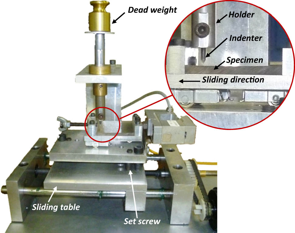
Experimental set-up used for single scratch tests (SST).
Experimental parameters considered for a scratch test
| Material |
|
|
|
|
|---|---|---|---|---|
| GFRP | 10–60 | 20–50 | 210 | 30 |
The tangential load was instantaneously recorded using a piezoelectric sensor, and the apparent friction coefficient (
2.3 SEM
SEM inspections were specially planned for finely investigating the wear mechanisms at the micromechanical scale. This technique can also ease to monitor the damage mechanisms at the micro level. Scratched samples were inspected to determine the changes in the damage mode. Samples were cut at the appropriate size and bonded on a silver-painted specimen holder, in the SEM chamber. The surface of samples should be electrically conductive; therefore, samples were coated with a thin gold layer. A 20 kV accelerating voltage was used to reach the required magnification. For each test, the damaged samples are scanned from the start to the end of the scratches, and the dominant wear mechanisms are noted.
3 Results and discussion
3.1 Scratch-induced damage modes
To point out the various micro-mechanisms dominating the tribological behavior of the composite, SEM inspections were performed on the wear grooves. It is worth noting that the damage modes vary significantly with the test parameters. Based on micrographs illustrated in Figures 2–4, multiple damage modes can be perceived. Irrespective of the fiber orientation, matrix discontinuous tearing, matrix ploughing, interface debonding, fiber erosion, multifracture, fracture, and pull-out seem to dominate the MRP. On the scratched surface, these modes can act alone or in association with each other, depending on the test parameters. It, however, appears that wear mechanisms dominating the MRP are sensitively governed by the active damage modes regardless of the testing conditions.

Wear scenarios and SEM micrographs emphasizing the SST // wear mechanisms. (a–c)
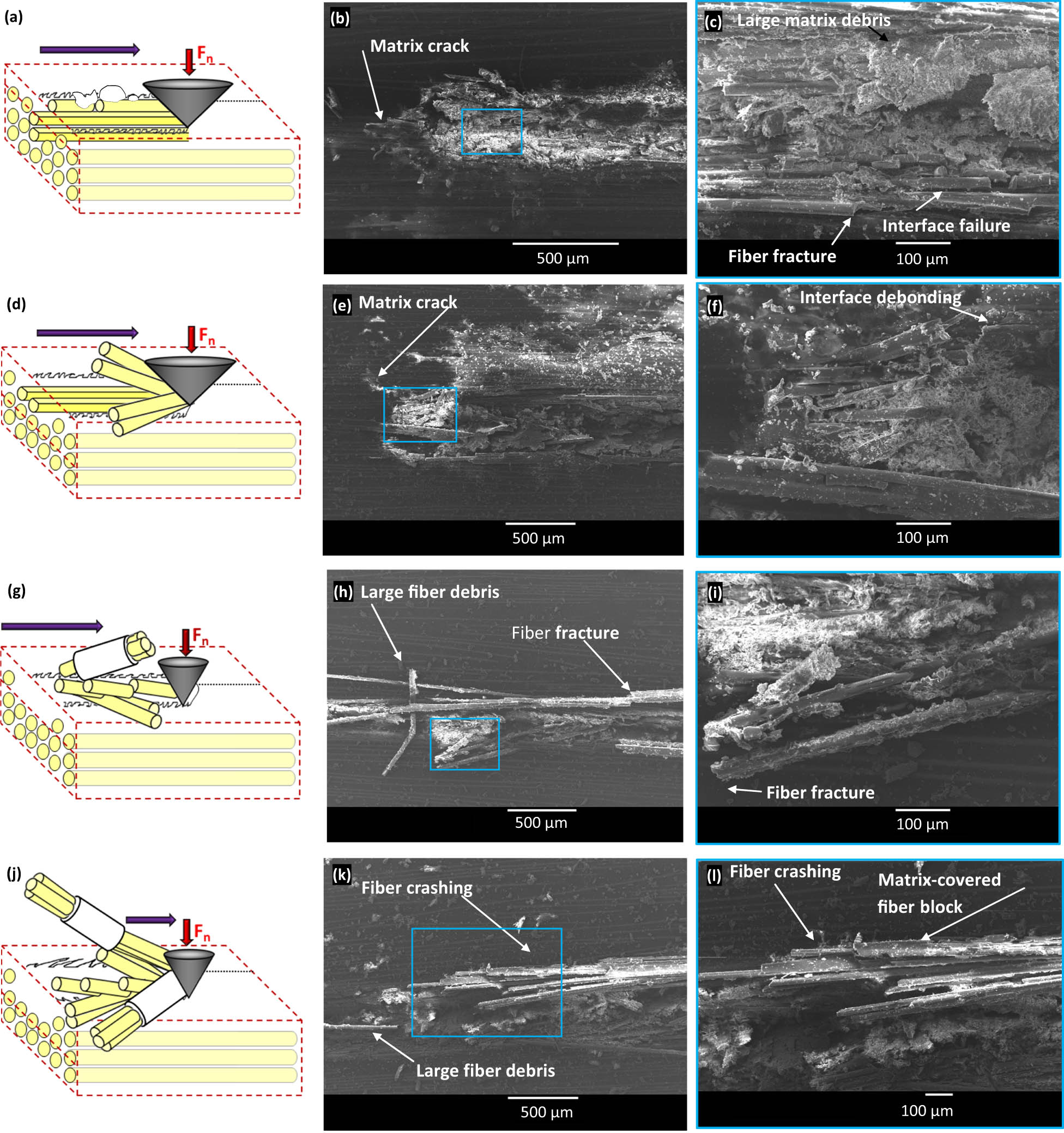
Wear scenarios and SEM micrographs emphasizing the SST // wear mechanisms. (a–c) θ = 45°− F n = 20 N, (d–f) θ = 45°− F n = 50 N, (g–i) θ = 60°− F n = 20 N, and (j–l) θ = 60°− F n = 50 N.

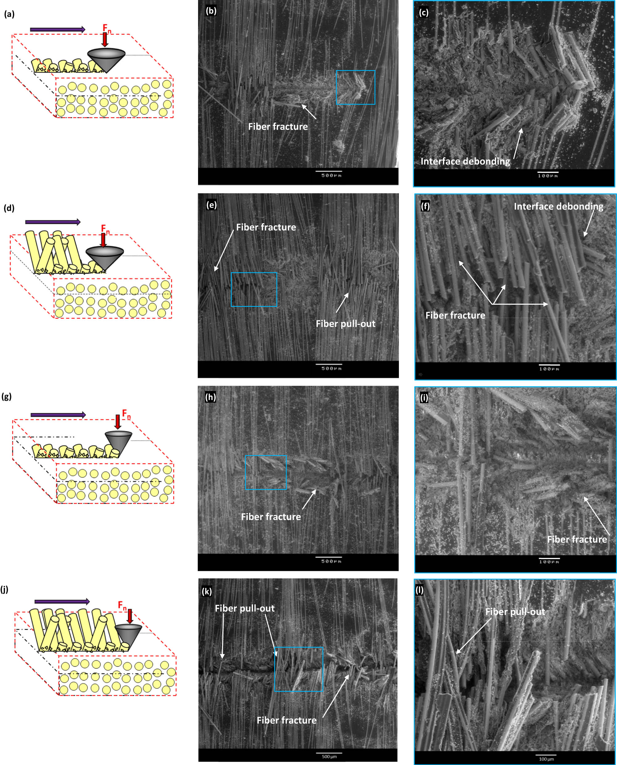
Wear scenarios and SEM micrographs emphasizing the SST⊥ wear mechanisms. (a–c) θ = 10°− F n = 20 N, (d–f) θ = 10°− F n = 50 N, (g–i) θ = 30°− F n = 20 N, and (j–l) θ = 30°− F n = 50 N.
3.1.1 MRP when SST//
When scratching parallel-to-fiber using the lowest attack angle, i.e., 10°, the wear mechanisms accentuate with the increasing applied normal load. Indeed, for a 20 N normal load, the matrix ploughing prevailed the damage mode in association with matrix superficial tearing (Figure 2a–c). However, increasing the normal load provokes a transition of damage modes to fiber erosion and fiber rupture in series, which may be observed in Figure 2d–f. Several authors have used diagrams and schema to highlight the phenomena of heterogeneous material damage [27,29,30]. Detailed diagrams are elaborated in this study. Figure 2a and d show the wear scenarios of the scratched composite, for 20 and 50 N normal loads, respectively. It appears that relatively low pressures (Figure 2a) yield a penetration lower than the superficial matrix layer that covers the glass fibers. In fact, the indenter-tip compresses the superficial composite layer yielding, hence, matrix ploughing without transferring damage to the fibers. However, the increase of the normal load (Figure 2d) increases the penetration depth, which affects the superficial fiber layer. At relatively high pressure, sliding provokes the erosion of discovered fibers associated with rupture in series especially at the superficial layer. The glass fibers exhibit a brittle behavior. The initiation of the fiber rupture is almost always perpendicular to the fiber direction. Similar wear mechanisms wear observed by Quintelier et al. [19]. They investigated the sliding wear behavior of the GFRP composite through SEM observations. The matrix superficial tearing parallel to fiber direction observed in Figure 2a–c may be a major cause of a later interface debonding. This result is also corroborated by Quintelier et al. [19].
Figure 2g–l shows the damage generated when using a 30° attack angle. While a succession of wear mechanisms combining both matrix ploughing and cracking take place at 20 N (Figure 2g–i), fiber fracture dominates at 50 N (Figure 2j–l). The wear scenarios observed at 20 N and 50 N are displayed in Figure 2g and j, respectively. At the lowest load (Figure 2g), the penetration of the indenter forms a groove throughout the polyester matrix associated with ploughing. It reveals that the former mechanisms prevail in damage mode, resulting hence in matrix cracks and debris throughout the formed groove. The increase of the normal load to 50 N induces the transition of dominating damage mode from ploughing to fiber fracture (Figure 2j). Under severe pressures, the indenter penetration increases and provokes the fracture of the fibers. Friedrich et al. [31] studied the scratch behavior of the carbon fiber reinforced polyether-etherketone composite using a diamond tip indenter. They proved that the shear-type debonding dominated the damage mechanisms when scratching parallel to fiber orientation, promoting then the beginning phase of the damage process. This debonding can produce the separation of the composite components and then a large decrease in its scratch resistance.
Figure 3a–f and g–l depict the wear mechanisms for 45 and 60° attack angles, respectively. For the lower attack angle, the interface debonding and fiber fracture dominate the damage mode under 20 N normal load (Figure 3a–c). Figure 3a illustrates the wear scenarios under the sub-mentioned conditions. The indenter penetration depth allows the indenter-tip to enter into contact with some fiber layer. The sliding action provokes the interface failure, while the fibers were compressed along the groove sides before being broken. Nevertheless, fiber crushing and fiber pull-out (Figure 3d–f) dominate the MRP at the highest load. Increasing the normal load generates a high penetration depth and, accordingly, increases the number of composite layers involved by the MRP. This promotes fiber pull-out as illustrated in Figure 3d.
For larger attack angle, i.e., 60°, the typical wear mechanisms particularly observed at 45° attack angle and low normal load switch to severe fiber fracture associated with large fiber debris (Figure 3g–l). Figure 3g exhibits the typical wear scenario acting under these conditions. A sharper indenter generated a deeper groove with smaller width magnifying the damage and provoking large debris. However, increasing the normal load for the same indenter angle yields deeper streaks inducing hence fiber crashing and interface failure. This generates large fiber debris and matrix-covered fiber blocks as can be observed in micrographs (Figure 3j–l). The sensitivity of the scratch deformation mode to the normal load was also confirmed by Man et al. [32] during scratching on continuous carbon fiber reinforced polyamide 6 composites.
3.1.2 MRP when SST⊥
When scratching perpendicular-to-fiber orientation, the wear operating on the composite reveals different behavior. Figure 4 shows the damage modes and various wear scenarios being involved within the material sensitivity to the testing parameters. For an attack angle of 10° and a normal load of 20 N, matrix ploughing controls substantially the MRP (Figure 4a–c). No scratch was formed owing to the low indenter penetration. In fact, the superficial polyester layer is not compressed enough to be severely damaged. The fibers were not especially affected. Typically, Figure 4a shows the wear scenario associated with this case. At low attack angle and load, the penetration depth remains lower than the superficial polyester layer thickness covering the fibers. The superficial matrix layer and the fiber layer did not undergo any damage. This finding is consistent with that of Briscoe [24] who studied the scratch behavior of the GFRP. They proved that when using the smallest attack angle, the dominant wear mechanism is viscoelastic-plastic or ductile ploughing. However, at the highest normal load, the damage accentuates resulting in a fracture-in-series of the fibers, associating both mode-I and mode-II. With the increasing normal load, the dominant damage mode switches from ploughing to fiber fracture-in-series (Figure 4d–f). According to the wear scenario shown in Figure 4d, increasing the normal load favors the material removal to the detriment of matrix flow. The fibers are directly exposed to the indenter-tip because of the failure of the superficial matrix layer. The fracture-in-series takes, therefore, dominating role in the MRP.
When scratching with a 30° attack angle, different damage modes were perceived (Figure 4g–l). While matrix ploughing acts at 20 N (Figure 4g–i), fiber fracture-in-series dominates at 50 N (Figure 4j–l). Figure 4g and j show the wear scenarios being generated on the composite at 20 and 50 N loads, respectively. At a relatively low normal load, the indenter penetrates into the polyester matrix and then provokes the groove when it slides (Figure 4g). The examination of the formed groove proves the dominance of ploughing mechanisms. Increasing the applied load to 50 N, the prevailing damage mode transforms from matrix ploughing to fiber fracture-in-series (Figure 4j).
Figure 5a–f and g–l highlights the elementary mechanisms controlling the material removal for 45 and 60° attack angles, respectively. Figure 5a and d describe the wear scenarios observed at 45°. It appears that fiber fracture operates together with interface debonding mechanisms to dominate the damage mode at the lowest normal load (20 N) (Figure 5b–c). The applied load involves a penetration enough deep to allow the indenter to come into contact directly with the fibers. Nevertheless, at the highest load, i.e., 50 N, MRP associates fiber fracture and fiber pull-out (Figure 5e–f). Increasing the normal load increases the number of fiber layers to be potentially in contact with the indenter. This should generate a reaction force at the indenter-tip relatively high enough to pull-out the fibers in front of the indenter-tip. However, it was observed that the former mechanisms involve particularly the superficial layers where the matrix phase undergoes premature fail around the fibers, target of substantial pull-out. In accordance with the result proved by Man et al. [32], during scratching on continuous carbon fiber reinforced polyamide 6 composites, the present results have shown that the interface debonding plays a key role in promoting the removal of the matrix phase surrounding the elementary fiber phase (Figure 5d), as well as the MRP of fiber and the size of the resulting debris.
Wear scenarios and SEM micrographs emphasizing the SST⊥ wear mechanisms. (a–c) θ = 45°− F n = 20 N, (d–f) θ = 45°− F n = 50 N, (g–i) θ = 60°− F n = 20 N, and (j–l) θ = 60°− F n = 50 N.
However, at a large attack angle of 60°, a deeper groove was generated even at a relatively low normal load i.e., 20 N (Figure 5g–i). The indenter passes across some plies causing hence catastrophic fiber breakage. Figure 5g depicts the typical fiber debris owing to MRP under these conditions. Because of the indenter acuity, the fiber fracture appears relatively localized. Nevertheless, increasing the normal load up to 50 N (Figure 5j–l) provokes the fibers to pull-out after being cut. The action of indenter during sliding entails progressive bending of the fibers against the tool-tip. The advance of the indenter enhances the critical loading of fibers, which eventually fail under a severe bending state. The penetration level being reached under these conditions promotes not only further pull-out but also a larger width of the damaged area [33] that can be easily observed through the generated groove (Figure 5k–l). In addition, the penetration reached at a large attack angle and a load was found to be responsible for much bigger debris if compared to the previous cases studied. Zan et al. [34] proved that the sliding perpendicular to the fiber direction of the diamond indenter against ceramic matrix composite provokes greater damage, namely, matrix fragmentation and fiber breakage, pull-out, and outcropping.
3.2 Friction analysis
3.2.1 Friction model
The apparent friction coefficient (
The Bowden and Tabor model [36] assumes that friction between two surfaces is essentially due to two fundamental physical processes: (i) shear adhesive micro-joints formed at the contact points and (ii) the ploughing of surfaces by the asperities. The force of the friction is thus the sum of a shear component due to adhesion (
It was proved that adhesive part (
According to the Bowden and Tabor model [36,40], the ploughing friction coefficient can be thus related to the attack angle (θ) as follows:
However, the adhesive friction force is given by:
where
Besides, for an elastic contact, the real contact area seems to be proportional to the normal force [41] and the adhesive friction force can hence be written as follows [42,43]:
where
where
where
3.2.2 Friction evolution
Figure 6a shows the evolution of the apparent friction coefficients versus the normal load for different attack angles when SST//. Two domains can be perceived. In domain 1, where the smallest attack angles were used,
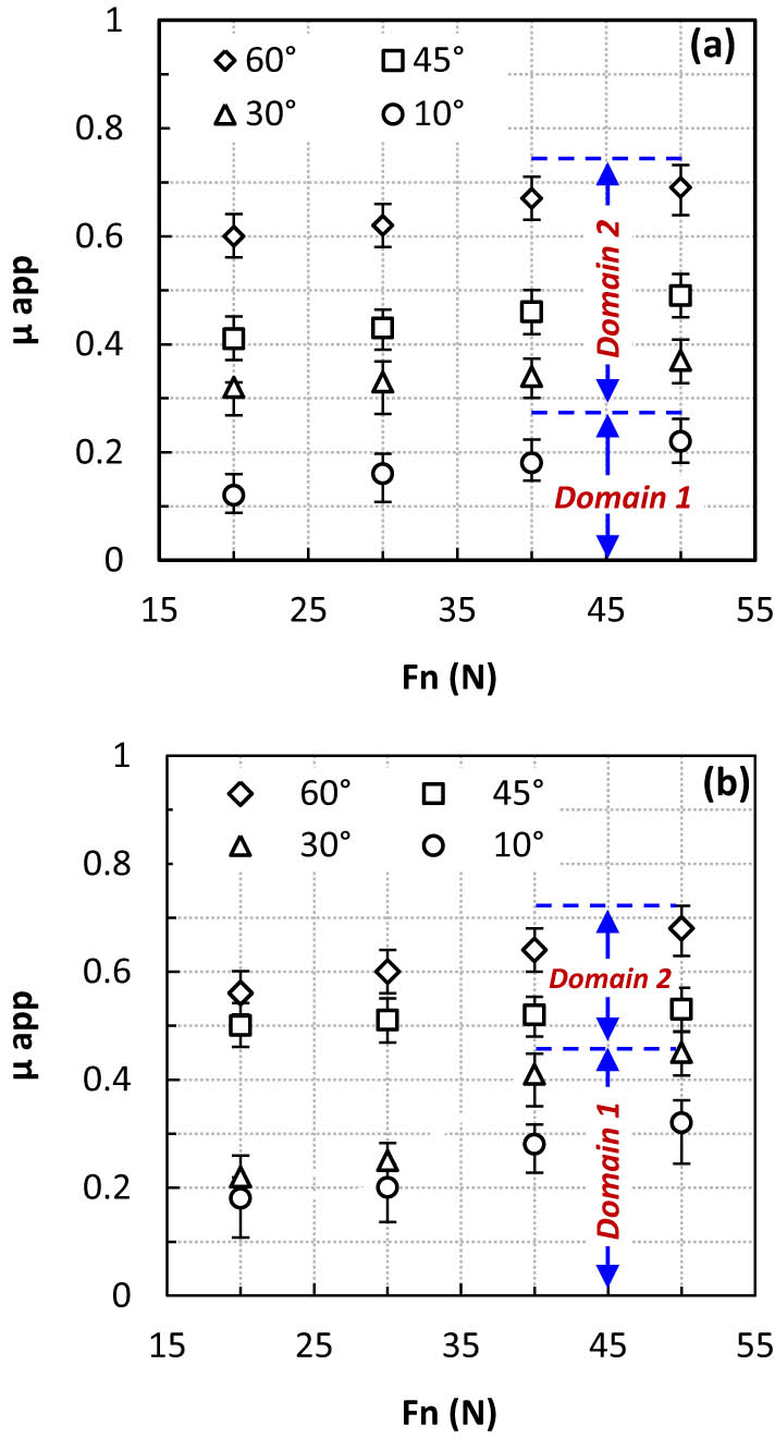
Evolution of
In domain 2, the apparent friction coefficient exhibits less sensitivity to normal load. In fact, increasing the normal load from 20 to 50 N, for 30, 45, and 60° attack angle, increases the apparent friction coefficient of about 14, 13, and 20%, respectively. The highest load, combined with the highest attack angle, yields the most severe contact conditions resulting in the catastrophic removal process. Increasing the normal load promotes the damage acting within the material.
The measurements enlighten also the sensitivity of the friction coefficient to the attack angle. The plots reveal monotonic raise with the attack angle, which reflects the undoubtful dependency of friction coefficient to the indenter shape. This evolution should correlate with the arrangement of dominant wear mechanisms versus the attack angle. From inspections, it was found that matrix tearing dominating the MRP at 10° transforms to matrix ploughing combined with premature fiber fracture at 30°. Interface failure together with fiber pull-out takes precedence at 45° attack angle, whereas fiber’s crushing and matrix tearing emerge beyond that value.
Figure 6b shows the evolution of the apparent friction coefficients versus the applied load for different attack angles using SST⊥. At low attack angles (Domain 1), the apparent friction coefficient still remains constant around 0.2, until 30 N. The apparent friction coefficient exhibits insensitivity to both parameters under low values, i.e.,
3.2.3 Friction prediction using response surfaces methodology
The application of response surface methodology (RSM) to the experimental data led to identifying the predicting law described by equation (8). This methodology consists to replace the complex part of experiments with one polynomial of degree lower than 3 and more simple to use which engenders a minimization in the experimental cost. The law’s constants
Friction law parameters and correlation coefficients obtained by RSM
| SST// |
|
|
|
|
Friction law |
| 0.47 | 0.18 | 0.7 | 0.98 |
|
|
|
|||||
| SST⊥ |
|
|
|
|
Friction law |
| 0.39 | 0.28 | 0.7 | 0.92 |
|
|

|
|||||
In general, the coefficient of determination R² defined by equation (9):
where
The coefficient R must be as close as possible to the value 1 (0 < R² < 1) [44].
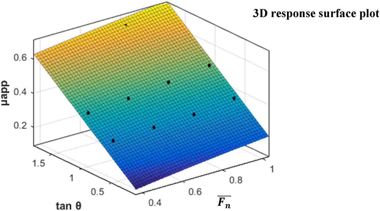
The reliability of the mathematical model may be assessed by refer to the measurements. According to 3D response surface plots (Table 2), it is conspicuous that measurements correlate well enough with the predictions obtained by the proposed model. The trends of predictions prove the good ability of the mathematical model to predict the apparent friction whatever the value of the attack angle not only within the considered parameters’ range but also by extrapolation out of these ranges. The results exhibit trends very similar irrespective of scratching direction. The reliability of the proposed mathematical model may also be estimated by the statistical coefficient of correlation (
3.2.4 Advantages of the proposed model
It is worth noting that experimentally it is so difficult to dissociate the ploughing and the adhesive component of the apparent friction coefficient. However, as given in equation (8), the predicted apparent friction coefficient is expressed as the sum of the ploughing and the adhesive friction coefficient. Figure 7 shows the proportion percentage of both ploughing and adhesive component of the predicted apparent friction coefficient as function of attack angle and normal load for SST// and SST⊥. When the low attack angle of 10° is used, the adhesive component of the predicted apparent friction coefficient is about 75 and 85% for SST// and SST⊥, respectively. This result seems to be in a good agreement with the experimental microscopic observations. Indeed, at relatively low attack angle, the composite is not yet damaged because of the low indenter penetration depth, leading to an only plastic deformation of the matrix (Figures 2a–c, 4a–c). Besides, increasing the normal load enlarges the contact surface and then slightly increases the adhesion between the indenter and the superficial layer. When the highest normal load is applied, the indenter tip reaches the first fiber layer and provokes rupture in series of fibers (Figures 2d–f, 4d–f). For an intermediate attack angle (

Proportion percentage of ploughing and adhesive component of the predicted apparent friction coefficient as a function of attack angle and normal load (a) SST// and (b) SST⊥.
Hence, the correlation between the predicted results and the experimental microstructural observations shows the accuracy of the proposed model, which allows a reliable separate detection of the ploughing and the adhesive component of the apparent friction coefficient.
3.3 Wear maps
Scratching of the considered composite inevitably yields a damaged area. The correlation between the damage modes (microscopic observations) and the test parameters allows the classification of the acting region of each damage mode. Consequently, after the analysis of the SEM micrographs, the wear maps were built so as to emphasize wear mechanism limits. Particular attention was paid to the sensitivity of the material deformation and dominant wear mechanisms to the tribological parameters.
Figure 8a and b depicts the wear maps of the scratched composite in case of perpendicular and parallel scratching, respectively. These maps illustrate the various domains, resulting in the MRP at a scratching speed of 210 mm/min. The plots reveal the influence of the test parameters, namely, the attack angle and the normal load on the prevailing damage mode. These parameters seem to play a crucial role in the switch of the damage mode from polyester matrix ploughing to brittle fiber fracture. Thereby, four prevailing damage modes were marked when SST⊥. The following remarks can be, hence, drawn.
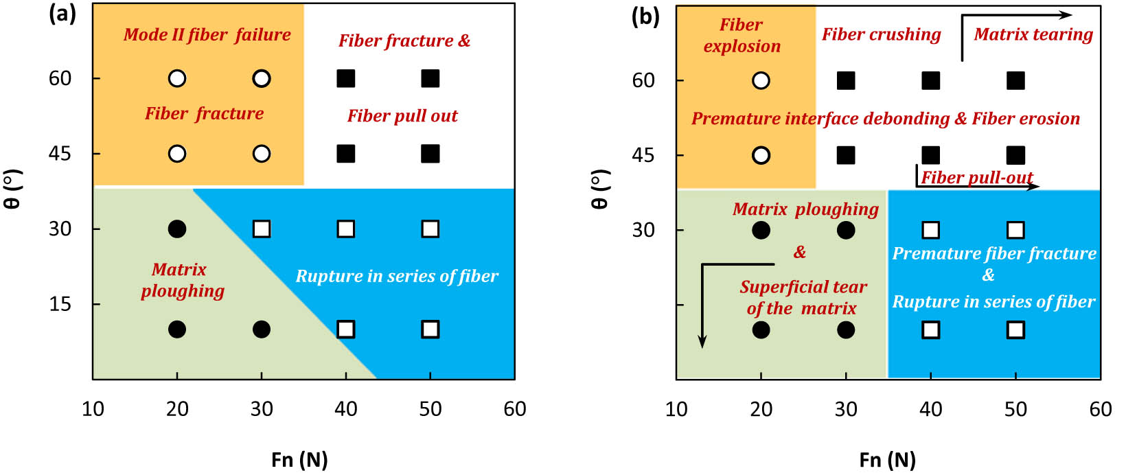
Wear maps obtained at (a) SST⊥ and (b) SST// (The back arrow points the start and the direction of the domination of wear mechanisms.).
At relatively law attack angles (
Using higher attack angle
When SST//, the prevailing domains were classified into four regions according to the SEM inspections as shown in Figure 8b. Thus, the following remarks can be drawn.
At relatively low attack angles, ploughing and discontinuous matrix tearing dominate the MRP at especially low normal load. Within this domain, the composite scratch behavior is governed by polyester matrix ploughing. The matrix plastic flow occurs due to the large plastic deformation around the indenter-tip. The scratching provokes neither severe matrix material removal nor fiber fracture. When sliding just under and close to the superficial glass fiber layer, the indenter affects the thin matrix surface by inducing micro-cracks.
When increasing load, the aforementioned dominant wear mechanisms, i.e., ploughing and discontinuous matrix tearing acting at relatively low loads, seem to transforms to fibers’ failure-in-series associated with premature fiber damage mode. The grooves were found deeper enough to eliminate the thin layer of the polyester matrix and to provoke the fibers discovering promoting, hence, their failure.
The prevailing damage mode was considered, at low normal load, as mainly being fiber explosion. This damage mode was induced by excessive buckling of fibers. In this domain, the interface failure induces matrix plastic flow around fibers. These latter were, hence, discovered and eroded.
However, under higher normal loads, the indenter penetration depth increases. The fibers were typically compressed and sheared until crashing. Nevertheless, under the highest load, the already-mentioned damage mode associates with matrix tearing. The premature interface failure dominates in correlation with fiber eroding and motivates the fiber pull-out damage mode. Indeed, at relatively high loads, the penetration depth increases enlarging, hence, the contact area between the indenter-tip and the superficial fiber layers. The fibers were pushed ahead up to failure and a typical fiber pull-out takes place.
4 Conclusions
This study deals with the analysis of elementary damage modes in a single indenter scratch test when sliding parallel and perpendicular to fiber orientation. Particular attention is granted to the correlation between the wear mechanisms and the test parameters, particularly, the normal load and the attack angle. Hence, the following conclusions can be drawn:
SEM micrographs of the UD-GFRP composite material reveal damage on the scratched surfaces. These wear mechanisms show a high sensitivity to the tribological parameters. At low attack angle and normal load matrix, ploughing still almost the same for both SST// and SST⊥, while interface fiber matrix debonding, fiber fracture, and pull-out were more pronounced in SST⊥ than those for SST//.
The attack angle has a significant effect on the apparent friction coefficient. Indeed, the increase of the attack angle induces the increase of the apparent friction coefficient up to three times larger. However, the effect of the normal load on the increase of apparent friction coefficient is less noticeable than the attack angle, i.e., (64%) at the lower attack angle and (14–23%) at the higher attack angle.
Higher attack angle and normal load provoke the transition of the prevailing damage mode from polyester matrix ploughing and rupture in series of fibers up to fibers crushing, matrix tearing, and fibers pullout in SST// and up to fiber fracture, mode II fiber failure, and fiber pullout in SST⊥.
Based on SST experimental results, a mathematical model taking into account the influence of the attack angle and the normal load was developed using RSM. The developed model has given a satisfactory and accurate result not only to predict friction behavior of UD-GFRP but also to detect the ploughing and the adhesive component of the apparent friction coefficient that could not be obtained experimentally.
The wear maps of the scratched UD-GFRP composite drawn for SST// and SST⊥, respectively, reveal four domains. Under low attack angle (
-
Funding information: This research did not receive any specific grant from funding agencies in the public, commercial, or not-for-profit sectors.
-
Conflict of interest: The authors have no conflicts of interest to declare. All co-authors have seen and agree with the whole contents of the manuscript. We certify that the submission is original work and is not under review at any other publication.
-
Data availability statement: The raw/processed data required to reproduce these findings cannot be shared at this time due to technical or time limitations.
References
[1] Kumar D, Pagar DD, Kumar R, Pruncu CI. Recent progress of reinforcement materials: A comprehensive overview of composite materials. Integr Med Res. 2019;8(6):6354–74.10.1016/j.jmrt.2019.09.068Search in Google Scholar
[2] Mandal P, Jesthi DK, Das D, Rout AK, Nayak RK. Three-body abrasion wear performance of glass/carbon fiber reinforced polymer hybrid composites. Mater Today Proc. 2018;5(9):20777–84.10.1016/j.matpr.2018.09.046Search in Google Scholar
[3] Zouggar K, Boukhoulda FB, Haddag B, Nouari M. Numerical and experimental investigations of S-Glass/Polyester composite laminate plate under low energy impact. Compos Part B Eng. 2016;89:169–86.10.1016/j.compositesb.2015.11.021Search in Google Scholar
[4] Nithin Kumar KC, Gupta G, Lakhera S, Shaikh A. Structural optimization of composite stiffened panel of a transport aircraft wing using CAE tools. Materials Today: Proceedings. Elsevier Ltd.; 2015. p. 2588–94.10.1016/j.matpr.2015.07.213Search in Google Scholar
[5] Farooq U, Myler P. Finite element simulation of buckling- induced failure of carbon fibre-reinforced laminated composite panels embedded with damage zones. Acta Astronaut. 2015;115:314–29.10.1016/j.actaastro.2015.05.039Search in Google Scholar
[6] Schmid ED, Salem DR. Fabrication technique and thermal insulation properties of micro- and nano-channeled polymer composites. Acta Astronaut. 2015;116:68–73.10.1016/j.actaastro.2015.06.015Search in Google Scholar
[7] Das D, Prakash O, Sharma M, Kumar R, Samal C. Mechanical properties and abrasion behaviour of glass fiber reinforced polymer composites – A case study. Mater Today Proc. 2019;19(2):506–11.10.1016/j.matpr.2019.07.644Search in Google Scholar
[8] Strumberger N, Gospocic A, Bartulic C. Polymeric Materials in Automobiles. Promet Traffic-Traffico. 2005;17(3):149–60.Search in Google Scholar
[9] Elwasli F, Zemzemi F, Mkaddem A, Mzali S, Mezlini S. A 3D multi-scratch test model for characterizing material removal regimes in 5083-Al alloy. Mater Des. 2015;87:352–62.10.1016/j.matdes.2015.07.121Search in Google Scholar
[10] Elleuch K, Mezlini S, Guermazi N, Kapsa P. Abrasive wear of aluminium alloys rubbed against sand. Wear. 2006;261(11–12):1316–21.10.1016/j.wear.2006.03.016Search in Google Scholar
[11] Guezmil M, Bensalah W, Mezlini S. Effect of bio-lubrication on the tribological behavior of UHMWPE against M30NW stainless steel. Tribol Int. 2016;94:550–9.10.1016/j.triboint.2015.10.022Search in Google Scholar
[12] Writzl V, Rovani AC, Pintaude G, Lima MSF, Guesser WL, Borges PC. Scratch resistances of compacted graphite iron with plasma nitriding, laser hardening, and duplex surface treatments. Tribol Int. 2020;143:106081.10.1016/j.triboint.2019.106081Search in Google Scholar
[13] Mzali S, Mezlini S, Zidi M. Effect of tribological parameters on scratch behaviour of unidirectional E-glass fibre reinforced polyester composite. Tribol - Mater Surf Interfaces. 2013;7(4):175–82.10.1179/1751584X13Y.0000000048Search in Google Scholar
[14] Carrión-Vilches FJ, González-Vivas A, Martínez-Mateo IJ, Bermúdez MD. Study of the abrasion resistance under scratching of polybutylenetereftalate-glass fi- ber composites. Tribol Int. 2015;92:365–78.10.1016/j.triboint.2015.07.004Search in Google Scholar
[15] Wee JW, Park SY, Choi BH. Observation and understanding of scratch behaviors of glass fi ber reinforced polycarbonate plates with various packing pressures during the injection molding process. Tribol Int. 2015;90:491–501.10.1016/j.triboint.2015.05.009Search in Google Scholar
[16] Chen J, An Q, Chen M. Transformation of fracture mechanism and damage behavior of ceramic-matrix composites during nano-scratching. Compos Part A Appl Sci Manuf. 2020;130:105756.10.1016/j.compositesa.2019.105756Search in Google Scholar
[17] Kohl JG, Bierwisch N, Ngo TT, Favaro G, Renget E, Schwarzer N. Determining the viscoelastic behavior of polyester fiberglass composite by continuous micro- indentation and friction properties. Wear. 2016;350–351:63–7.10.1016/j.wear.2016.01.005Search in Google Scholar
[18] Kim SS, Shin MW, Jang H. Tribological properties of short glass fiber reinforced polyamide 12 sliding on medium carbon steel. Wear. 2012;274–275:34–42.10.1016/j.wear.2011.08.009Search in Google Scholar
[19] Quintelier J, De Baets P, Samyn P, Van Hemelrijck D. On the SEM features of glass-polyester composite system subjected to dry sliding wear. Wear. 2006;261:703–14.10.1016/j.wear.2006.01.006Search in Google Scholar
[20] Omidi M, Khodabandeh A, Nategh S, Khakbiz M. Wear mechanisms maps of CNT reinforced Al6061 nanocomposites treated by cryomilling and mechanical milling. Tribol Int. 2017;110:151–60.10.1016/j.triboint.2017.01.033Search in Google Scholar
[21] Kato K. Micro-mechanisms of wear – wear modes. Wear. 1992;153(1):277–95.10.1016/0043-1648(92)90274-CSearch in Google Scholar
[22] Shibata K, Yamaguchi T, Urabe T, Hokkirigawa K. Experimental study on microscopic wear mechanism of copper/carbon/rice bran ceramics composites. Wear. 2012;294–295:270–6.10.1016/j.wear.2012.07.004Search in Google Scholar
[23] Iqbal T, Briscoe BJ, Luckham PF. Scratch deformations of poly (etheretherketone). Wear. 2011;271(7–8):1181–93.10.1016/j.wear.2011.05.033Search in Google Scholar
[24] Briscoe BJ. Scratch hardness as an evaluation of cure temperature for glass fibre reinforced polyester. Compos Sci Technol. 1989;34:73–90.10.1016/0266-3538(89)90078-XSearch in Google Scholar
[25] Mzali S, Mkaddem A, Elwasli F, Mezlini S. Towards an advanced modeling of failure mechanisms’ interaction in fiber-reinforced polyester: A mixed-mode loading concept. Compos Struct. 2017;160:70–80.10.1016/j.compstruct.2016.10.074Search in Google Scholar
[26] Wang J, Liu YB, An J, Wang LM. Wear mechanism map of uncoated HSS tools during drilling die-cast magnesium alloy. Wear. 2008;265:685–91.10.1016/j.wear.2007.12.009Search in Google Scholar
[27] Mezlini S, Ben Tkaya M, El Mansori M, Zahouani H, Kapsa P. Correlation between tribological parameters and wear mechanisms of homogeneous and heterogeneous material. Tribol Lett. 2009;33(2):153–9.10.1007/s11249-008-9403-5Search in Google Scholar
[28] Kishore P, Seetharamu S, Murali A, Kumar R. On the SEM features of glass–epoxy composite system subjected to dry sliding wear. Wear. 2001;247(2):208–13.10.1016/S0043-1648(00)00537-8Search in Google Scholar
[29] Davim J, Paulo J, Campos Rubio AMA. A novel approach based on digital image analysis to evaluate the delamination factor after drilling composite laminates. Compos Sci Technol. 2007;67(9):1939–45.10.1016/j.compscitech.2006.10.009Search in Google Scholar
[30] Davim JP, Reis P, António CC. Experimental study of drilling glass fiber reinforced plastics (GFRP) manufactured by hand lay-up. Compos Sci Technol. 2004;64(2):289–97.10.1016/S0266-3538(03)00253-7Search in Google Scholar
[31] Friedrich K, Váradi K, Goda T, Giertzsch. H. Finite element analysis of a polymer composite subjected to a sliding steel asperity Part II: Parallel and anti-parallel fibre orientations. J Mater Sci. 2002;37(16):3497–507.10.1023/A:1016571324836Search in Google Scholar
[32] Man Z, Wan B, Wang H, Li Q, Chang L. Experimental and numerical study on scratch performance of additively manufactured continuous carbon fibre reinforced polyamide 6 composites. Compos Sci Technol. 2022;230(2):109314.10.1016/j.compscitech.2022.109314Search in Google Scholar
[33] Mzali S, Elwasli F, Mkaddem A, Mezlini S. A micromechanical scratch model to investigate wear mechanisms in UD-GFRP composites. Mech Ind. 2018;19(3):305.10.1051/meca/2018011Search in Google Scholar
[34] Zan Z, Guo K, Sun J, Lu Y, Yang B, Jia X, et al. Investigation on scratching force and material removal mechanism of 3D SiCf/C–SiC composites during single grain scratching. J Eur Ceram Soc. 2022;42:5366–79.10.1016/j.jeurceramsoc.2022.05.079Search in Google Scholar
[35] Blau PJ. Friction coefficient. Encyclopedia of tribology. Wang QJ, editor. Boston, MA: Springer; 2013. p. 1304–6.10.1007/978-0-387-92897-5_169Search in Google Scholar
[36] Bowden FP, Tabor D. The friction and lubrication of solids. 2001st edn. Oxford: Oxford University Press; 1950. p. 424.10.1093/oso/9780198507772.001.0001Search in Google Scholar
[37] Gérald Zambelli Z, Vincent L. Matériaux et contacts: Une Approche Tribologique. Lausanne [Paris: Presses polytechniques et universitaires romandes]; 1998.Search in Google Scholar
[38] Wredenberg F, Larsson PL. Scratch testing of metals and polymers: Experiments and numerics. Wear. 2009;266(1–2):76–83.10.1016/j.wear.2008.05.014Search in Google Scholar
[39] Lafaye S, Gauthier C, Schirrer R. A surface flow line model of a scratching tip: Apparent and true local friction coefficients. Tribol Int. 2005;38(2):113–27.10.1016/j.triboint.2004.06.006Search in Google Scholar
[40] Felder E, Bucaille JL. Mechanical analysis of the scratching of metals and polymers with conical indenters at moderate and large strains. Tribol Int. 2006;39:70–87.10.1016/j.triboint.2005.04.005Search in Google Scholar
[41] Archard JF. Elastic deformation and the contact of surfaces. Nature. 1953;172:918–9.10.1038/172918a0Search in Google Scholar
[42] Chand N, Fahim M. Tribology of natural fiber polymer composites. 1st edn. Cambridge, England: Woodhead Publishing; 2008. p. 220.10.1201/9781439832592Search in Google Scholar
[43] Menezes PL, Kailas SV, Lovell MR. Fundamentals of engineering surfaces. Tribology for scientists and engineers from basics to advanced concepts. New York: Springer Science + Business Media New; 2013. p. 39.10.1007/978-1-4614-1945-7_1Search in Google Scholar
[44] Batmaz I, Tunali S. Small response surface designs for metamodel estimation. Eur J Oper Res. 2003;145(2):455–70.10.1016/S0377-2217(02)00207-2Search in Google Scholar
© 2023 the author(s), published by De Gruyter
This work is licensed under the Creative Commons Attribution 4.0 International License.
Articles in the same Issue
- Regular Articles
- Effects of cellulose nanofibers on flexural behavior of carbon-fiber-reinforced polymer composites with delamination
- Damage mechanisms of bismaleimide matrix composites under transverse loading via quasi-static indentation
- Experimental study on hydraulic fracture behavior of concrete with wedge-splitting testing
- The assessment of color adjustment potentials for monoshade universal composites
- Metakaolin-based geopolymers filled with volcanic fly ashes: FT-IR, thermal characterization, and antibacterial property
- The effect of temperature on the tensile properties and failure mechanisms of two-dimensional braided composites
- The influence of preparation of nano-ZrO2/α-Al2O3 gradient coating on the corrosion resistance of 316L stainless steel substrate
- A numerical study on the spatial orientation of aligning fibrous particles in composites considering the wall effect
- A simulative study on the effect of friction coefficient and angle on failure behaviors of GLARE subjected to low-velocity impact
- Impact resistance capacity and degradation law of epoxy-coated steel strand under the impact load
- Analytical solutions of coupled functionally graded conical shells of revolution
- The influence of water vapor on the structural response of asphalt pavement
- A non-invasive method of glucose monitoring using FR4 material based microwave antenna sensor
- Chloride ion transport and service life prediction of aeolian sand concrete under dry–wet cycles
- Micro-damage analysis and numerical simulation of composite solid propellant based on in situ tensile test
- Experimental study on the influence of high-frequency vibratory mixing on concrete performance
- Effects of microstructure characteristics on the transverse moisture diffusivity of unidirectional composite
- Gradient-distributed ZTAp-VCp/Fe45 as new anti-wear composite material and its bonding properties during composite casting
- Experimental evaluation of velocity sensitivity for conglomerate reservoir rock in Karamay oil field
- Mechanical and tribological properties of C/C–SiC ceramic composites with different preforms
- Mechanical property improvement of oil palm empty fruit bunch composites by hybridization using ramie fibers on epoxy–CNT matrices
- Research and analysis on low-velocity impact of composite materials
- Optimizing curing agent ratios for high-performance thermosetting phthalonitrile-based glass fibers
- Method for deriving twisting process parameters of large package E-glass yarn by measuring physical properties of bobbin yarn
- A probability characteristic of crack intersecting with embedded microcapsules in capsule-based self-healing materials
- An investigation into the effect of cross-ply on energy storage and vibration characteristics of carbon fiber lattice sandwich structure bionic prosthetic foot
- Preparation and application of corona noise-suppressing anti-shedding materials for UHV transmission lines
- XRD analysis determined crystal cage occupying number n of carbon anion substituted mayenite-type cage compound C12A7: nC
- Optimizing bending strength of laminated bamboo using confined bamboo with softwoods
- Hydrogels loaded with atenolol drug metal–organic framework showing biological activity
- Creep analysis of the flax fiber-reinforced polymer composites based on the time–temperature superposition principle
- A novel 3D woven carbon fiber composite with super interlayer performance hybridized by CNT tape and copper wire simultaneously
- Effect of aggregate characteristics on properties of cemented sand and gravel
- An integrated structure of air spring for ships and its strength characteristics
- Modeling and dynamic analysis of functionally graded porous spherical shell based on Chebyshev–Ritz approach
- Failure analysis of sandwich beams under three-point bending based on theoretical and numerical models
- Study and prediction analysis on road performance of basalt fiber permeable concrete
- Prediction of the rubberized concrete behavior: A comparison of gene expression programming and response surface method
- Study on properties of recycled mixed polyester/nylon/spandex modified by hydrogenated petroleum resin
- Effect of particle size distribution on microstructure and chloride permeability of blended cement with supplementary cementitious materials
- In situ ligand synthesis affording a new Co(ii) MOF for photocatalytic application
- Fracture research of adhesive-bonded joints for GFRP laminates under mixed-mode loading condition
- Influence of temperature and humidity coupling on rutting deformation of asphalt pavement
- Review Articles
- Sustainable concrete with partial substitution of paper pulp ash: A review
- Durability and microstructure study on concrete made with sewage sludge ash: A review (Part Ⅱ)
- Mechanical performance of concrete made with sewage sludge ash: A review (Part Ⅰ)
- Durability and microstructure analysis of concrete made with volcanic ash: A review (Part II)
- Communication
- Calculation of specific surface area for tight rock characterization through high-pressure mercury intrusion
- Special Issue: MDA 2022
- Vibration response of functionally graded material sandwich plates with elliptical cutouts and geometric imperfections under the mixed boundary conditions
- Analysis of material removal process when scratching unidirectional fibers reinforced polyester composites
- Tailoring the optical and UV reflectivity of CFRP-epoxy composites: Approaches and selected results
- Fiber orientation in continuous fiber-reinforced thermoplastics/metal hybrid joining via multi-pin arrays
- Development of Mg-based metal matrix biomedical composites for acicular cruciate ligament fixation by reinforcing with rare earth oxide and hydroxyapatite – A mechanical, corrosion, and microstructural perspective
- Special Issue: CACMSE
- Preparation and application of foamed ceramic panels in interior design