Fracture research of adhesive-bonded joints for GFRP laminates under mixed-mode loading condition
-
Zhi-peng Zhong
 and
Wen-zheng Ju
and
Wen-zheng Ju

Abstract
The mixed-mode fracture characterization of adhesively bonded glass fiber-reinforced polymer (GFRP) plate joints is studied based on theoretical and experimental techniques. An improved beam model is used to estimate the compliance and the mixed-mode energy release rate (ERR) for GFRP four-point mixed-mode bending specimens. In this model, the deformation of the upper and lower GFRP plates is mutually independent, and the deformable adhesive is considered to satisfy the displacement compatibility conditions on the bonding interface. The explicit theoretical solutions of the compliance and ERR using the compliance method are reduced. The present theoretical solutions fit well with the finite element solutions by comparison with the rigid joint model. From the critical loads in experiment, the variation in fracture toughness on mixed-mode I/II has been determined by modifying the stiffness of the composite GFRP/GFRP substrate.
1 Introduction
The bridge deck structures composed of glass fiber-reinforced polymer (GFRP) have been widely applied in bridge structures at present. The characteristics of using GFRP bridge deck include fatigue and corrosion resistance, light weight, and high strength [1,2,3]. A GFRP bridge deck system can be integrated by adhesive-bonding several modular tube [4]. However, failure analysis showed that the weakest occurred at the adhesive bonding joints in the entire structure. The phenomenon of failure takes place owing to one or several cracks’ initiation and propagation in the joint [5,6]. For the orthotropic GFRP bridge decks, owing to the complex nature of bonded joint, an undesirable failure mode is found as the crack can extend in various paths inside the joint. This mixed failure mode is because of inappropriate bonding between the adherend and the adhesive, owing to inappropriate selection of the adhesive or poor surface preparation. To investigate this troublesome failure mode, the mixed-mode I/II fracture analysis has been widely used by the comparison between the actual energy release rate (ERR or G) and its fracture toughness G c [7,8]. Therefore, to assess the safety and applications of the structure bonding joints, the criterion of the mixed-mode I/II fracture of adhesively bonded GFRP joints is needed.
To obtain the fracture toughness G c and the determination of mixed-mode evaluation criterion of bonded interface, a lot of beam-type fracture specimens have been conducted. The mixed-mode bending (MMB) experiment is appropriate for the determination of mixed-mode failure criterion or failure envelops, and it has been used in American society for testing and materials (ASTM) [9]. The MMB experiment, which originally was put forward by Crews and Reeders and then improved by the same authors to guard against nonlinearities, is usually employed for the research of I/II mixed fracture conditions [10]. The interfacial fracture test for three-layer deposited metal layers and two-layer under four-point bending was conducted by Klingbeil and Beuth [11]. An explicit solution of ERR was also compared to the numerical result. The experiment of bi-layer laminates consisting of aluminum–aluminum composites under four-point bending was carried out by Zhang and Lewandoski [12]. The influence of the interfacial properties on the mechanical behavior of laminated structures is also considered. The mixed-mode I/II fracture behavior for delamination growth in multidirectional laminates considering the fiber-bridging effect was investigated by Gong et al. [13] under MMB tests. From experiments, the mixed-mode ERR Gc was measured. However, the whole strain ERR about the mixed-mode fractures is obtained in the aforementioned literature, and the mode decomposition is not derived.
To evaluate the crack behavior in bonding interface accurately, the mode components to the total fracture energy should be known clearly. A series of studies for the mode separation have been performed in the existing literature [14,15,16,17,18]. The interfacial delamination characteristics of graphite/epoxy composite materials were examined by Jurf and Pipes [14]. In this model, the critical fracture strain ERR for the opening, the shearing, and the mixed mode was determined experimentally. What is more, a quadratic fit was obtained by the experimental result. A prior knowledge about the effect of Mode I and Mode II on the cracking in GFRP–concrete bonded interface was built up by Liu and Qiao [15]. In this model, the whole ERR and the mode components with respect to Mode I and Mode II were developed. The fracture criteria for GFRP/steel joint were established by Jiang et al. [16], in which the mixed-mode relationship was investigated considering the Mode-I and Mode-II ERR. The experimental results were consistent with the finite element (FE) results. Chang et al. [17] established the linear, quadratic, and elliptical functions of Mode-I and Mode-II ERR by observing mixed failure mode of granite. The experimental failures could be suitable to some types of fitting curves. The bi-layer beam considering shear deformation was developed by Wang and Qiao [18], in which the separation of Mode-I and Mode-II ERRs was finished by the J-integral and superposition method. The interlaminar fracture toughness of thick fiber composite materials was analyzed using finite element method (FEM) by Agrawal and Jar [19]. The mode decomposition is applicable for the corrected beam with regard to different thickness specimens. Zhang et al. [20] investigated the mixed-mode fracture of adhesively bonded joints composited of pultruded composite lap by experiment. Owing to some differentia (i.e., joint geometrical configurations and failure mode) from the laminated components, they believed that the fracture behavior for the adhesively bonded pultruded laminate joints in the field of civil engineering should be studied. Shahverdi et al. [21] experimentally used asymmetric MMB specimens to investigate the mixed-mode fracture behavior of adhesively bonded pultruded GFRP joints.
From the aforementioned review, it can be concluded that GFRP laminate delamination was found in most of the literature, and the fracture toughness of determination can be obtained on the basis of available standardization. In the bridge structures, GFRP bridge deck comprising pultruded adherends connected by a moderately thick layer of adhesive (1–3 mm) is acceptable [20]. There are few studies on the analytical solutions of the fracture behavior of the GFRP bridge deck comprising a glued layer. Actually, the failure mode of the adhesive bonding joints is different from that of the GFRP laminates delamination. Therefore, it is necessary to establish the reasonableness and analytical formulas on determining the mixed-mode I/II fracture toughness of the FRP member adhesive-bonding joints. The mixed-mode fracture mechanism of adhesive-bonded composite GFRP joints adopting pultruded GFRP four-point MMB (4-MMB) specimens is studied in this article. Based on the sub-layer GFRP laminated beam theory, the deflection, ERR, and compliance of mixed-mode fracture specimens are induced later, in which the effect of moderately thick adhesive layer is considered in the model, where the continuous conditions of the displacements on the interface between the adherend and adhesive are satisfied. Combining loading conditions with continuous requirement of each sub-layer, the mathematical formula for the compliance and ERR of 4-MMB specimen is provided. In this model, the deformation of the upper and lower GFRP plates is mutually independent, and the deformable adhesive is considered to satisfy the displacement compatibility conditions on the bonding interface. The explicit theoretical solutions of the compliance and ERR using the compliance method are reduced. The comparison of the results obtained by the improved model and those by FE analysis (FEA) demonstrates the validity and accuracy of the current model. The designed 4-MMB specimens with varying the thickness of GFRP plates are used to realize various distinct fracture mode I/II mixities and to obtain the fracture toughness of GFRP adhesive-bonded composite joints based on the critical load. The fracture toughness of GFRP adhesive-bonded composite joints can be used to predict crack initiation.
2 Analysis of GFRP 4-MMB specimen within the adhesive layer
A draw of the GFRP 4-MMB specimen is seen in Figure 1. The span length of the specimen is L, the top beam and bottom beam thicknesses are h 1 and h 2, and the beam breadth is b. The unbonded length is a, and the adhesive layer thickness is h a embedded in the bonding area. The forces P act on points of x = L 0 and x = a + L 1, where the symmetric loading is considered in 4-MMB configuration and the length a + L 1 = L − L 0. In this study, the left rollers can be modeled as the origin of coordinate.
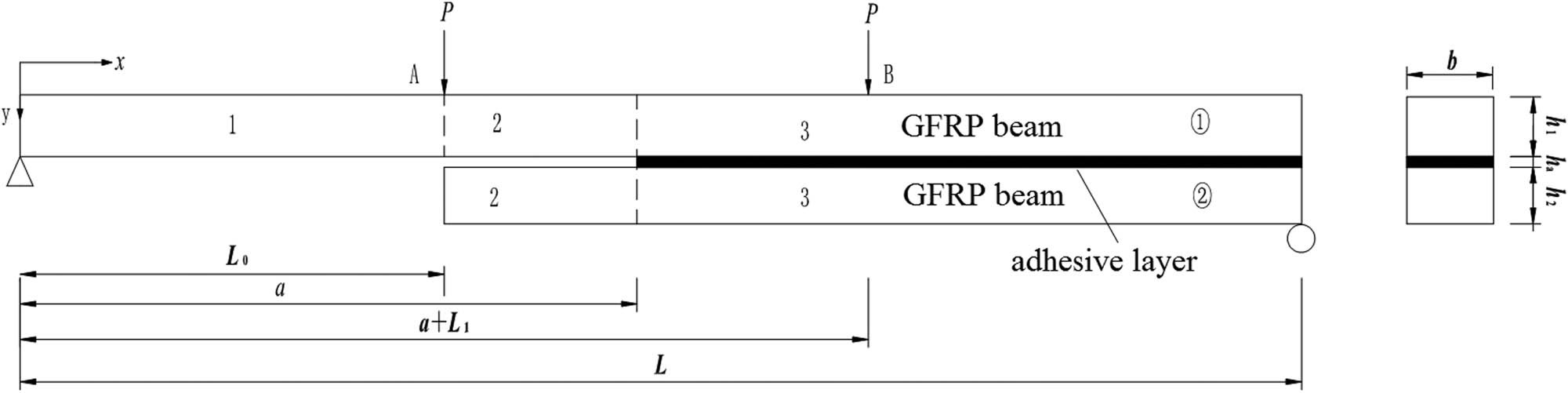
Configuration of the 4-MMB beam.
As shown in Figure 1, when the body in uncracked area (a < x < L) is isolated first, the stress resultant in cross-section is shown based on beam theory (Figure 2). Q i , N i , and M i (i = 1,2) are defined as the internal transverse shear forces, axial forces and bending moments of sub-layers 1 and 2, respectively.

Infinitesimal isolated body configuration of sub-layers.
According to the isolated body equilibrium condition, the relationship between the stresses and internal forces are expressed by:
where
According to the composite material beam theory, the constitutive equations of the internal forces and displacements for each sub-layer can be described as:
where
According to the overall equilibrium conditions:
where
By combining equations (1)–(7), the differential equation of deflection is reduced:
where
According to the superposition principle, when the 4-MMB remains linear-elastic, the longitudinal displacement of sub-layers consists of three parts: the axial displacement of the sub-layers, the distinct rotation angle of the upper and lower plates, and the rotation angle caused by the global flexural deformation of the lower and upper adherends. Each part of the deformation can be calculated independently, and the summation is the total deformation.
Taking into account three deformation, the lower surface longitudinal displacement for the upper layers
The upper surface displacement for lower layers
where
Combined with equations (9) and (10), the stress and displacement of adhesive layer can be described as:
The second derivative of equation (11) yields
For the configuration of 4-MMB specimens, considering symmetric cross-ply composite triangular laminated plates, the vertical compression is neglected, i.e.,
where
The deflection of the uncracked region
where
For the cracking region 1
Taking equations (14) and (15) into equation (4), the deflection is reduced to:
For the cracking region 2
Taking equations (16) and (17) into equation (4), the deflection is obtained by:
The undetermined coefficients of 4-MMB are obtained by the following boundary conditions and continuous conditions:
where
Then, the deflections of the left loading point and the right loading point of 4-MMB can be established as:
Similar to the compliance method used in the literature [22,23,24], the single applied load on loading position is P, and then, the total load is 2P acting on the inner span. The load-point displacement
The compliance C is then given as follows:
When the compliance of the specimen is achieved, then following [23], the ERR of the 4-MMB is calculated accurately based on the compliance method by combining with equation (23):
As displayed in equation (24), G is unrelated to the crack length, which shows that this critical value G c can still be obtained by the critical load P c through the experiment without measuring the crack propagation length in the fracture experiment process.
3 Mathematical model verification and discussion
To examine the reasonableness of this proposed model, the closed results for

Typical load–deformation curves for 4-MMB specimen.
The comparison of the compliance values for the 4-MMB specimens by the present model, the FEA, and rigid joint model is displayed in Figure 4. As demonstrated in Figure 4a, all of these models demonstrate that the compliance is straightly dependent on the length of crack. However, the rigid joint model relatively underrates the compliance due to neglecting the adhesive deformation. By accounting for the distinct rotation of sub-layer and adhesive deformation, the present solution should be a better approximation to the results from FEA than the rigid joint model.

Typical compliance and ERR with respect to crack length for 4-MMB: (a) compliance and (b) ERR.
The ERR G of adhesive joint crack can be calculated by the VCCT in FEA. The change of ERR with respect to the cracking length using the proposed model, rigid-joint model, and FE method is displayed in Figure 4(b). As seen in Figure 4(b), when compared with the present model, the rigid-joint model undervalues the ERR due to neglect the adhesive deformation. What is more, the present calculated ERR is much closer to the result from FEA with maximum divergence of 3.8%, which reveals that the presently proposed model is useful as the determination of ERR G.
4 Experimental characterization of GFRP-bonded 4-MMB test
In this section, a series of experiments are applied to study the fracture toughness on interfacial delamination of FRP material. Scarce studies in the aforementioned investigations have been found to discuss the determination of FRP-bonded fracture toughness with a certain thickness binder. Unlike interfacial delamination in FRP material, the crack growth of the bonded joint is instable and the failure types (e.g., cohesive failure, interfacial debonding) are more complicated. In this section, an experimental program using 4-MMB specimen was conducted to portray the mixed-mode fracture behavior for GFRP-bonded joint interface. By varying the thickness of GFRP sub-layer, the mixed fracture modes can be conducted.
The 4-MMB specimens compounded from pultruded GFRP laminate and two-component epoxy binder are bonded, and a Teflon film length a was set up on the side of bonded beam to produce the pre-crack. The thin GFRP laminate plates are produced from the E-glass fiber fabric and epoxy resin by pultrusion process. Adhesive consists of two-component epoxy and curing agent. The proportioning of adhesive layer is as follows: epoxy resin:curing agent = 1:1. The material mechanical parameters of pultruded GFRP and binder listed in Table 1 are measured in accordance with ASTM. All specimens were fabricated at room temperature. To realize a standard thickness of the binder and good neatness of the GFRP laminates, the steel clamps are applied for the production of the specimens to ensure that the adhesive has a certain thickness. After fabrication, all 4-MMB specimens were solidified at room temperature for 48 h. The fracture experiments were operated on a hydraulic universal experimental machine, and a four-point flexure loading schematic diagram is shown in Figure 5, where the span of beam L = 260 mm, the length between the left supports and loading point L 0 = 80 mm, and the width b = 40 mm. By varying the sub-layer height, a different mixed-mode fracture was characterized.
Mechanical parameters of GFRP laminate and binder
| Material name | E x (GPa) | E y (GPa) | ν xy | G xy (GPa) | E 1f (GPa) |
|---|---|---|---|---|---|
| GFRP laminate | 34.9 | 7.29 | 0.29 | 3.92 | 32.5 |
| Binder | 1.5 | 1.5 | 0.30 | 0.58 | 1.5 |

4-MMB experimental setup: (a) universal test machine apparatus and (b) configuration and loading for 4-MMB test.
The fracture experiments were launched adopting displacement control, and the loading rate is 0.5 mm/min. The load–displacement data and curve were continuously and automatically saved by the computer programs. In the experiment, the load acts on the specimens until the occurrence of complete bonded interfacial crack propagation for determining the critical loads for cracking and crack inhibition. A typical the load versus the deflection curve for the adhesively bonded GFRP 4-MMB specimen is displayed in Figure 6. At first, the displacement gradually linear increases with the applied load. Correspondingly, the crack tip of the bonded specimen accumulates the elastic strain energy. As the strain energy reaches to the cracking threshold value, the tiny crack propagates in the bonded joints and the elastic energy is converted into surface energy. The crack initial load P c is characterized by a decrease in load. And then, the applied load is dropped, and the crack propagating arrests. From Figure 7, it appears that the crack propagates along the bonding interface, which shows that the bond fracture toughness of the GFRP–GFRP component is lower than the fracture toughness of interlamination of GFRP and the bonding interface is a weak link.

Classic load–deformation curve for 4-MMB specimen.

Failure modes of GFRP-bonded specimens: (a) crack propagation along the bonded interface and (b) failure of bond surface.
To obtain mode Ⅰ and mode Ⅱ ERR, the change of fracture mode ratios G Ⅰ/G Ⅱ with the variation of GFRP beam thicknesses is shown in Figure 8, in accordance with the global mode decomposition method [30]. As shown in Figure 8, the mode ratios of G Ⅰ/G Ⅱ decrease as the thickness ratios of h 1/h 2 increase. When h 1/h 2 is equal to 6, the mode ratios of G Ⅰ/G Ⅱ decrease slowly and then tend to be close to constant. So the maximum thickness ratio of h 1/h 2 is chosen 6 in the experiment. Then, according to the load–deflection curve, the total critical ERR G c, mode Ⅰ and Ⅱ ERR of the GFRP bonded interface are determined by substituting the critical load P c into equation (26) (Table 2). Consequently, the mixed-mode fracture ratio value G Ⅰ/G Ⅱ for different h 1/h 2 is shown in Table 2a–d, which evaluates the interfacial bonding characterization under the mixed-mode condition. The 4-MMB specimens are used to estimate the compliance and the mixed-mode ERR by changing the ratio of h 1/h 2 in this study. The mixed-mode fracture ratio G Ⅰ/G Ⅱ is determined by the h 1/h 2 rather than h, and the impact of h is negligible.

Variation of GⅠ/GⅡ for the different ratio of h 1/h 2.
Peak loads P c and fracture toughness G c for h 1/h 2 values
| Specimen | Peak loads P C (N) | G Ⅰ (J/m2) | G Ⅱ (J/m2) | G c (J/m2) | G Ⅰ/G Ⅱ |
|---|---|---|---|---|---|
| (a) | Peak loads P c and fracture toughness G c for h 1 / h 2 = 0.5 | ||||
| 4-MMBa-1 | 262 | 114.79 | 75.89 | 190.68 | 1.51 |
| 4-MMBa-2 | 246 | 101.20 | 66.90 | 168.10 | 1.51 |
| 4-MMBa-3 | 291 | 141.61 | 93.62 | 235.23 | 1.51 |
| 4-MMBa-4 | 249 | 103.68 | 68.54 | 172.22 | 1.51 |
| 4-MMBa-5 | 286 | 136.78 | 90.43 | 227.21 | 1.51 |
| Mean value | 266.80 | 119.61 | 79.08 | 198.68 | 1.51 |
| COV (%) | 7.79 | 15.61 | 15.61 | 15.61 | 0 |
| (b) | Peak loads P c and fracture toughness G c for h 1 / h 2 = 1 | ||||
| 4-MMBb-1 | 286 | 117.98 | 88.48 | 206.46 | 1.33 |
| 4-MMBb-2 | 292 | 122.98 | 92.23 | 215.21 | 1.33 |
| 4-MMBb-3 | 241 | 83.77 | 62.83 | 146.60 | 1.33 |
| 4-MMBb-4 | 289 | 120.46 | 90.35 | 210.81 | 1.33 |
| 4-MMBb-5 | 276 | 109.87 | 82.40 | 192.27 | 1.33 |
| Mean value | 276.80 | 111.01 | 83.26 | 194.27 | 1.33 |
| COV (%) | 7.55 | 14.42 | 14.42 | 14.42 | 0 |
| (c) | Peak loads P c and fracture toughness G c for h 1 / h 2 = 2 | ||||
| 4-MMBc-1 | 780 | 81.04 | 73.34 | 154.38 | 1.10 |
| 4-MMBc-2 | 918 | 112.25 | 101.58 | 213.83 | 1.10 |
| 4MMBc-3 | 1,008 | 135.34 | 122.48 | 257.82 | 1.10 |
| 4-MMBc-4 | 793 | 83.76 | 75.80 | 159.56 | 1.10 |
| 4-MMBc-5 | 889 | 105.27 | 95.27 | 200.54 | 1.10 |
| Mean value | 877.60 | 103.53 | 93.69 | 197.22 | 1.10 |
| COV (%) | 10.73 | 21.53 | 21.53 | 21.53 | 0 |
| (d) | Peak loads P c and fracture toughness G c for h 1 / h 2 = 6 | ||||
| 4-MMBd-1 | 7,035 | 110.96 | 134.61 | 245.57 | 0.82 |
| 4-MMBd-2 | 5,663 | 71.90 | 87.22 | 159.12 | 0.82 |
| 4-MMBd-3 | 7,269 | 118.46 | 143.71 | 262.17 | 0.82 |
| 4-MMBd-4 | 5,774 | 74.74 | 90.68 | 165.42 | 0.82 |
| 4-MMBd-5 | 7,619 | 130.14 | 157.88 | 288.02 | 0.82 |
| Mean value | 6,672 | 101.24 | 122.82 | 224.06 | 0.82 |
| COV (%) | 13.43 | 26.08 | 26.08 | 26.08 | 0 |
5 Conclusions
In this study, a 4-MMB specimen of pultruded GFRP laminates is conducted for researching the interface fracture behavior of GFRP joint under mixed-mode loading condition. The comparison of classical bi-layer beam model (rigid joint model) and improved beam model including layered orthotropic adherends and an epoxy adhesive layer can provide more accurate values of compliance and ERR in the 4-MMB specimen.
Base on the model, linear correlations of the average compliance versus cracking length, as well as the constant relationship between the ERR and cracking length, are determined. The designed 4-MMB specimens by changing the thickness of GFRP plates achieve various fracture mode I/II mixities and experimentally measure the fracture threshold of GFRP adhesive-bonded composite joints based on the critical load.
-
Funding information: The work is supported by the Nanjing Vocational Institute of Railway Technology, Research Platform of Intelligent Detection Research Center for Transit Infrastructure (KYPT2023003), and the Southeast University, Key Laboratory of Concrete and Prestressed Concrete Structure of Ministry of Education (CPCSME 2015-03).
-
Conflict of interest: The authors state no conflict of interest.
-
Data availability statement: All data included in this study are available upon request by contact with the corresponding author.
Appendix A Parameter of adhesively bonded GFRP 4-MMB model
References
[1] Ali HT, Akrami R, Fotouhi S, Bodaghi M, Saeedifar M, Yusuf M, et al. Fiber reinforced polymer composites in bridge industry. Structures. 2021;30:774–85.10.1016/j.istruc.2020.12.092Search in Google Scholar
[2] Liu Z, Majumdar PK, Cousins TE, Lesko JJ. Development and evaluation of an adhesively bonded panel-to-panel joint for a FRP bridge deck system. J Compos Constr. 2008;12(2):224–33.10.1061/(ASCE)1090-0268(2008)12:2(224)Search in Google Scholar
[3] Keller T, Theodorou NA, Vassilopoulos AP, De Castro J. Effect of natural weathering on durability of pultruded glass fiber–reinforced bridge and building structures. J Compos Constr. 2016;20(1):04015025.10.1061/(ASCE)CC.1943-5614.0000589Search in Google Scholar
[4] Zhou A, Keller T. Joining techniques for fiber reinforced polymer composite bridge deck systems. Compos Struct. 2005;69(3):336–45.10.1016/j.compstruct.2004.07.016Search in Google Scholar
[5] Shang X, Marques E, Machado J, Carbas R, Jiang D, Silva LFMD. Review on techniques to improve the strength of adhesive joints with composite adherends. Composites. 2019;177(107363):1–15.10.1016/j.compositesb.2019.107363Search in Google Scholar
[6] Jiang Z, Wan S, Zhong Z, Li S, Shen K. Effect of curved delamination front on mode-I fracture toughness of adhesively bonded joints. Eng Fract Mech. 2015;138:73–91.10.1016/j.engfracmech.2015.03.020Search in Google Scholar
[7] Cañas J, Távara L, Blázquez A, Estefani A. Overview of Gc Tests Used to Evaluate Composite–Composite Adhesive Joints. J Multiscale Model. 2019;10(03):1826–37.10.1142/S1756973718420027Search in Google Scholar
[8] Zhong ZP, Hong L. Mode II Fracture of GFRP laminates bonded interfaces under 4-ENF test. Adv Mater Sci Eng. 2017;2017:1–10.10.1155/2017/3792346Search in Google Scholar
[9] Benzeggagh ML, Kenane MJ. Measurement of mixed-mode delamination fracture toughness of unidirectional glass/epoxy composites with mixed-mode bending apparatus. Compos Sci Technol. 1996;56(4):439–49.10.1016/0266-3538(96)00005-XSearch in Google Scholar
[10] Reeder JR, Crews JH. Redesign of the mixed-mode bending delamination test to reduce nonlinear effects. J Compos Tech Res. 1992;14(1):12–9.10.1520/CTR10078JSearch in Google Scholar
[11] Klingbeil NW, Beuth JL. Interfacial fracture testing of deposited metal layers under four-point bending. Eng Fract Mech. 1997;56(1):113–26.10.1016/S0013-7944(96)00109-9Search in Google Scholar
[12] Zhang J, Lewandowski JJ. Delamination study using four-point bending of bilayers. J Mater Sci. 1997;32(14):3851–6.10.1023/A:1018692110821Search in Google Scholar
[13] Gong Y, Zhao L, Zhang J, Wang Y, Hu N. Delamination propagation criterion including the effect of fiber bridging for mixed-mode I/II delamination in CFRP multidirectional laminates. Compos Sci Technol. 2017;151:302–9.10.1016/j.compscitech.2017.09.002Search in Google Scholar
[14] Jurf RA, Pipes RB. Interlaminar fracture of composite materials. J Compos Mater. 1982;16(5):386–94.10.1177/002199838201600503Search in Google Scholar
[15] Liu Q, Qiao P. Mixed mode fracture characterization of GFRP-concrete bonded interface using four-point asymmetric end-notched flexure test. Theor Appl Fract Mech. 2017;92:155–66.10.1016/j.tafmec.2017.06.009Search in Google Scholar
[16] Jiang Z, Fang Z, Yan L, Wan S, Fang Y. Mixed-mode I/II fracture criteria for adhesively-bonded pultruded GFRP/steel joint. Compos Struct. 2020;255:113012.10.1016/j.compstruct.2020.113012Search in Google Scholar
[17] Chang SH, Lee CI, Jeon S. Measurement of rock fracture toughness under modes I and II and mixed-mode conditions by using disc-type specimens. Eng Geol. 2002;66(1–2):79–97.10.1016/S0013-7952(02)00033-9Search in Google Scholar
[18] Wang J, Qiao P. On the energy release rate and mode mix of delaminated shear deformable composite plates. Int J Solids Struct. 2004;41(9–10):2757–79.10.1016/j.ijsolstr.2003.11.039Search in Google Scholar
[19] Agrawal A, Jar P. Analysis of specimen thickness effect on interlaminar fracture toughness of fibre composites using finite element models. Compos Sci Technol. 2003;63(10):1393–402.10.1016/S0266-3538(03)00088-5Search in Google Scholar
[20] Zhang Y, Vassilopoulos AP, Keller T. Fracture of adhesively-bonded pultruded GFRP joints under constant amplitude fatigue loading. Int J Fatigue. 2010;32(7):979–87.10.1016/j.ijfatigue.2009.11.004Search in Google Scholar
[21] Shahverdi M, Vassilopoulos AP, Keller T. Mixed-Mode I/II fracture behavior of asymmetric adhesively-bonded pultruded composite joints. Eng Fract Mech. 2014;115:43–59.10.1016/j.engfracmech.2013.11.014Search in Google Scholar
[22] Martin RH, Davidson BD. Mode II fracture toughness evaluation using four point bend, end notched flexure test. Plast Rubber Compos. 1999;28(8):401–6.10.1179/146580199101540565Search in Google Scholar
[23] Valvo PS. On the calculation of energy release rate and mode mixity in delaminated laminated beams. Eng Fract Mech. 2016;165:114–39.10.1016/j.engfracmech.2016.08.010Search in Google Scholar
[24] Wang J, Qiao P. Novel beam analysis of end notched flexure specimen for mode-II fracture. Eng Fract Mech. 2004;71(2):219–31.10.1016/S0013-7944(03)00096-1Search in Google Scholar
[25] ASTM D3039/D3039M-14. Standard Test Method for Tensile Properties of Polymer Matrix Composite Materials [S]. Philadelphia: ASTM; 2014.Search in Google Scholar
[26] ASTM D3518/D3518M-13. Standard test method for in-plane shear response of polymer matrix composite materials by tensile test of a ± 45° Laminate [S]. Philadelphia: Mater ASTM; 2013.Search in Google Scholar
[27] Heidari-Rarani M, Sayedain M. Finite element modeling strategies for 2D and 3D delamination propagation in composite DCB specimens using VCCT, CZM and XFEM approaches. Theor Appl Fract Mech. 2019;103:102246.10.1016/j.tafmec.2019.102246Search in Google Scholar
[28] Krueger R. Virtual crack closure technique: History approach and applications. Appl Mech Rev. 2004;57(2):109–43.10.1115/1.1595677Search in Google Scholar
[29] Jiang Z, Wan S, Zhong Z, Li M, Shen K. Determination of mode-I fracture toughness and non-uniformity for GFRP double cantilever beam specimens with an adhesive layer. Eng Fract Mech. 2014;128:139–56.10.1016/j.engfracmech.2014.07.011Search in Google Scholar
[30] De Moura M, Gonçalves JPM, Fernandez MV. Fatigue/fracture characterization of composite bonded joints under mode I, mode II and mixed-mode I + II. Compos Struct. 2016;139:62–7.10.1016/j.compstruct.2015.11.073Search in Google Scholar
© 2023 the author(s), published by De Gruyter
This work is licensed under the Creative Commons Attribution 4.0 International License.
Articles in the same Issue
- Regular Articles
- Effects of cellulose nanofibers on flexural behavior of carbon-fiber-reinforced polymer composites with delamination
- Damage mechanisms of bismaleimide matrix composites under transverse loading via quasi-static indentation
- Experimental study on hydraulic fracture behavior of concrete with wedge-splitting testing
- The assessment of color adjustment potentials for monoshade universal composites
- Metakaolin-based geopolymers filled with volcanic fly ashes: FT-IR, thermal characterization, and antibacterial property
- The effect of temperature on the tensile properties and failure mechanisms of two-dimensional braided composites
- The influence of preparation of nano-ZrO2/α-Al2O3 gradient coating on the corrosion resistance of 316L stainless steel substrate
- A numerical study on the spatial orientation of aligning fibrous particles in composites considering the wall effect
- A simulative study on the effect of friction coefficient and angle on failure behaviors of GLARE subjected to low-velocity impact
- Impact resistance capacity and degradation law of epoxy-coated steel strand under the impact load
- Analytical solutions of coupled functionally graded conical shells of revolution
- The influence of water vapor on the structural response of asphalt pavement
- A non-invasive method of glucose monitoring using FR4 material based microwave antenna sensor
- Chloride ion transport and service life prediction of aeolian sand concrete under dry–wet cycles
- Micro-damage analysis and numerical simulation of composite solid propellant based on in situ tensile test
- Experimental study on the influence of high-frequency vibratory mixing on concrete performance
- Effects of microstructure characteristics on the transverse moisture diffusivity of unidirectional composite
- Gradient-distributed ZTAp-VCp/Fe45 as new anti-wear composite material and its bonding properties during composite casting
- Experimental evaluation of velocity sensitivity for conglomerate reservoir rock in Karamay oil field
- Mechanical and tribological properties of C/C–SiC ceramic composites with different preforms
- Mechanical property improvement of oil palm empty fruit bunch composites by hybridization using ramie fibers on epoxy–CNT matrices
- Research and analysis on low-velocity impact of composite materials
- Optimizing curing agent ratios for high-performance thermosetting phthalonitrile-based glass fibers
- Method for deriving twisting process parameters of large package E-glass yarn by measuring physical properties of bobbin yarn
- A probability characteristic of crack intersecting with embedded microcapsules in capsule-based self-healing materials
- An investigation into the effect of cross-ply on energy storage and vibration characteristics of carbon fiber lattice sandwich structure bionic prosthetic foot
- Preparation and application of corona noise-suppressing anti-shedding materials for UHV transmission lines
- XRD analysis determined crystal cage occupying number n of carbon anion substituted mayenite-type cage compound C12A7: nC
- Optimizing bending strength of laminated bamboo using confined bamboo with softwoods
- Hydrogels loaded with atenolol drug metal–organic framework showing biological activity
- Creep analysis of the flax fiber-reinforced polymer composites based on the time–temperature superposition principle
- A novel 3D woven carbon fiber composite with super interlayer performance hybridized by CNT tape and copper wire simultaneously
- Effect of aggregate characteristics on properties of cemented sand and gravel
- An integrated structure of air spring for ships and its strength characteristics
- Modeling and dynamic analysis of functionally graded porous spherical shell based on Chebyshev–Ritz approach
- Failure analysis of sandwich beams under three-point bending based on theoretical and numerical models
- Study and prediction analysis on road performance of basalt fiber permeable concrete
- Prediction of the rubberized concrete behavior: A comparison of gene expression programming and response surface method
- Study on properties of recycled mixed polyester/nylon/spandex modified by hydrogenated petroleum resin
- Effect of particle size distribution on microstructure and chloride permeability of blended cement with supplementary cementitious materials
- In situ ligand synthesis affording a new Co(ii) MOF for photocatalytic application
- Fracture research of adhesive-bonded joints for GFRP laminates under mixed-mode loading condition
- Influence of temperature and humidity coupling on rutting deformation of asphalt pavement
- Review Articles
- Sustainable concrete with partial substitution of paper pulp ash: A review
- Durability and microstructure study on concrete made with sewage sludge ash: A review (Part Ⅱ)
- Mechanical performance of concrete made with sewage sludge ash: A review (Part Ⅰ)
- Durability and microstructure analysis of concrete made with volcanic ash: A review (Part II)
- Communication
- Calculation of specific surface area for tight rock characterization through high-pressure mercury intrusion
- Special Issue: MDA 2022
- Vibration response of functionally graded material sandwich plates with elliptical cutouts and geometric imperfections under the mixed boundary conditions
- Analysis of material removal process when scratching unidirectional fibers reinforced polyester composites
- Tailoring the optical and UV reflectivity of CFRP-epoxy composites: Approaches and selected results
- Fiber orientation in continuous fiber-reinforced thermoplastics/metal hybrid joining via multi-pin arrays
- Development of Mg-based metal matrix biomedical composites for acicular cruciate ligament fixation by reinforcing with rare earth oxide and hydroxyapatite – A mechanical, corrosion, and microstructural perspective
- Special Issue: CACMSE
- Preparation and application of foamed ceramic panels in interior design