An investigation into the effect of cross-ply on energy storage and vibration characteristics of carbon fiber lattice sandwich structure bionic prosthetic foot
-
Meijiao Jiang


Abstract
Made a pioneering attempt to use the lattice sandwich structure in prosthetic foot design and pioneered the study for the lay-up design of the prosthetic foot. An innovative carbon fiber bionic prosthetic foot was designed using a sandwich structure. The effect of cross-ply on the prosthetic foot’s energy storage properties and vibration characteristics was investigated using the lattice sandwich structure prosthetic foot. The bionic prosthetic foot’s finite element model was constructed under normal working conditions according to international standards. The results indicate that the storage of strain energy increases with an increase in cross-ply under heel-strict working conditions. Under the toe-off condition, the strain energy distribution increases with the increase in cross-ply. The cross-ply number influences the mode of displacement of the bionic foot. The natural frequencies of the bionic foot increase with the increase in the cross-ply.
1 Introduction
Due to the anisotropic mechanical properties of fiber-reinforced composites, changes in layup design can cause significant responses in energy absorption [1]. The stiffness is directly related to the energy storage characteristics of the foot and ankle prosthesis, and both energy storage characteristics and vibration characteristics are important design criteria for foot and ankle prostheses.
Sandwich structure composites have been applied in aerospace, automobiles, and other fields with higher specific stiffness and strength than carbon fiber laminate structure composites. In this article, we attempt to design a prosthetic foot using sandwich composites and investigate the effect of sandwich structural panel layup design on the energy storage and vibration characteristics of the prosthetic foot.
Cross-layered structures were applied to the layup design of composites. In recent years, the lay-up design of carbon fiber-reinforced composites has been studied a lot.
The Bouligand structure, which is prevalent in fish scales and arthropod cuticles, is a fibrous laminate in which the direction of the fibers gradually changes across the thickness [2]. Recently, researchers have become more interested in complex three-dimensional fracture processes (crack twisting) as a potential source of toughness. In their investigation of the bending of antisymmetric cross-ply laminates, Rodrigues et al. [3] selected five of the most well-liked high-order shear deformation theories (HSDTs) that have been reported in the literature. The Radial Point Interpolation Method was utilized to research the bending of antisymmetric cross-ply laminates using HSDTs. Different laminates were analyzed using the radial point interpolation method and HSDTs. The accuracy and robustness of the numerical technique are demonstrated by comparisons between meshless solutions and analytical and finite element method solutions that are published in the literature. Sasikumar et al. [4] created an asymmetrical laminate by combining plies of varying thicknesses. The suggested unsymmetrical hybrid laminate’s damage sequence was compared to that of the thin-ply baseline using C-scan inspection on impacted and quasi-statically indented specimens. The expected delamination area was lowered by the hybrid laminate’s bottom intermediate plies, which also delayed and reduced fiber damage. To determine the lay-up of composite laminates with several plies, Fedon et al. [5] presented a brand-new deterministic optimizer. A method that employs beam search to explore the design space encourages quick convergence to optimum or nearly optimal solutions. It is demonstrated that the suggested optimizer can quickly recover symmetric laminate lay-ups with up to 300 plies. Ply drop sequence (PDS) is a concept that Yang et al. [6] proposed for building composite laminate constructions with many sections. For the PDS-based blending optimization, a genetic algorithm (GA) with specific operators and codification is used, which ensures that the design is thoroughly blended within the GA rounds. To show the adaptability and potential of the suggested strategy, it is applied to a benchmark issue with 18 panels called the horseshoe problem. An innovative method for the vibration and damping analysis of arbitrary curved n-layered sandwich beams is presented by Arikoglu and Ozturk [7]. A parametric mid-section curve and a frequency-dependent viscoelastic core in a spiral-shaped sandwich beam are explored. The analysis of the core thickness and subtended angle’s impact on vibration and damping behavior is done in great detail. Xu et al. [8] provided a governing equation for forecasting the free vibration of the graded corrugated lattice core sandwich beam using the continuous homogeneous theory. To solve the governing equation for various kinds of boundary conditions, the Rayleigh–Ritz technique is used. The theoretical predictions are verified by numerical simulations and experimental findings, and the natural frequencies are determined. The effects of the face sheet thickness, core height, beam length, and graded parameters were investigated on the natural frequencies of the graded corrugated lattice core sandwich beams. The vibrational behavior of smart orthotropic cross-ply laminated stepped beams is studied by Fazeli et al. [9]. To determine the natural frequencies and forced vibrational response of a smart carbon fiber/poly ether-ether-ketone cantilever beam, experimental research was conducted to test the correctness of the analytical approach. Comparisons show how effectively and accurately the offered closed-form technique can forecast the free and forced vibrational behavior of smart-stepped laminated composite beams.
The vibration characteristics and mechanical properties of cross-layered structures have been studied in depth in theory and experiments, but relatively little research has been done on the mechanical and vibration characteristics of cross-layers under specific operating conditions.
Although sandwich structure composite materials have been applied in many fields, prosthetic foot manufacturing materials are mainly laminated. The following literature discusses the stiffness research methods of lattice sandwich structures.
Zhang et al. [10] suggested a brand-new pyramid lattice sandwich construction with active variable stiffness, The structure exhibits good active and self-adjusting vibration reduction. The dynamics equations for the entire structure are developed using the assumed modes approach, Hamilton’s principle, and supersonic piston theory. Xiao et al. [11] suggested using multiscale topology optimization as a design strategy for graded lattice sandwich structures (GLSSs). The distribution optimization of lattice cells in the core layer and the thickness optimization of two solid face sheets are both implemented based on the Kriging metamodel. To demonstrate the benefits of the suggested strategy, numerical examples of compliance and natural frequency optimization of GLSSs are given. The findings of bending tests show that GLSSs have bigger natural frequencies and are stiffer than uniform lattice sandwich constructions. According to Ghannadpour et al. [12], who introduced 10 strut-based topologies of the lattice-core sandwich beams, the octet-truss structure resisted far larger deflection, star and diamond structures had higher stiffness, and they are the best option in the sandwiches under compressive and bending loads. It was clear that Grid had a superior reaction under compressive loads while having the poorest response to three-point bending. A novel heterogeneous glass sponge lattice structure with a circle-/grid-like appearance (GSLS) was created by He et al. [13]. The FEA simulation demonstrates that the heterogeneous unit cell in the GSLS may improve strut connection, distribute stress, and display a distinct fracture process of cell-after-cell and layer-by-layer. According to an approach presented by Bai et al. [14], new types of curving lattice structures may be created using a circular or elliptical arc in the lattice struts. Its mechanical qualities were significantly improved by changing the original stress distribution under the loads and efficiently relieving the stress concentration at the struts’ nodes.
The fundamental theory of lattice structure, design and preparation techniques, and stiffness and damage modes of lattice sandwich structures are all covered in earlier research on this topic. Lattice sandwich technology has never been used in a prosthetic foot. The lattice sandwich structure is employed to offer substantial stiffness for research into the bionic performance of prostheses because it possesses the properties of energy absorption cushioning, low relative density, high specific stiffness, and specific strength.
Stiffness is an important design index of the prosthetic foot. Adamczyk et al. [15] developed and assessed a technique for measuring the angular stiffness of the prosthetic foot using a straightforward linear compression test by calculating the angular stiffness as a function of tower angle, normal force, and center of pressure concerning the rate of change of linear displacement. In an experimental foot prosthesis, Adamczyk et al. [16] adjusted the stiffness of the forefoot and the hindfoot. They then calculated the results of these computations, including the prosthesis’ energy return, center of mass mechanics, ground reaction forces, and joint mechanics, and determined how sensitive these variables were to component stiffness. To determine the impact of foot stiffness on kinematics, kinetics, muscle activity, prosthetic energy storage return, and mechanical efficiency during amputee walking, Fey et al. [17] carried out a thorough biomechanical investigation. Furthermore, it identifies the impact of changed prosthetic foot stiffness on muscle and foot function using forward dynamics models of amputee walking [18]. Five experimental feet were utilized in the investigation to assess the impact of prosthetic foot forefoot flexibility on oxygen costs [19]. Flexibility has a big impact on the preference ranking. The number of flexural hinges in the forefoot regions of the experiment was changed to affect flexibility. According to the study’s findings, solid-ankle prosthetic foot models with excessively flexible forefoot parts may have a “drop-off” impact in late stance and when switching loads between the prosthetic and contralateral limbs [20].
Bionic methods based on gait analysis, anthropometric data, exercise oxygen consumption, and mechanical performance tests are mostly used in the structural design of the prosthetic foot.
Hamzah and Ghannadpour [21] presented a brand-new carbon fiber-epoxy composite ankle prosthesis concept. The design has a good energy return reaction and a smooth roll-over shape. Jang et al. [22] created a flexible keel for an energy-storing prosthesis while creating a cost function for the keel’s performance assessment. The contribution of each element to the cost function was explored. The ideal flexible keel was made with better energy storage capacity and is appropriate for more vigorous prosthesis walking. Alleva et al. [23] constructed a dimensionless kinematic model of the lower limb to determine the angle of the lower limb during gait. following the creation of a prototype prosthesis with a mechanical design. The ankle joint angle during stride resembled that of a healthy person, according to early tests of the prototype performed by itself in the lab.
Previous studies have shown that stiffness and energy storage characteristics are important indicators affecting the performance of prosthetic foot. However, the effects of cross-ply on the energy storage characteristics and dynamic character of prostheses foot are unclear. This article presents an innovative lattice sandwich structure bionic prosthetic foot, introducing a pyramid lattice sandwich structure to provide walking stiffness and determine its walking characteristics according to ISO standards. Finally, the effect of the layered design of the lattice sandwich structure on the energy storage characteristics and vibration performance of the prosthetic foot is discussed.
2 Methods
Energy storage characteristics and vibration characteristics are the key indicators of the prosthetic foot. In this article, we study the effect of cross-ply on the energy storage characteristics and vibration characteristics of prosthetic foot. When the structural system is deformed elastically under the action of external forces, energy is stored in the structure in the form of strain energy, and the larger the strain energy is, the better the energy storage characteristics of the structure. Therefore, this article adopts strain energy as an index to study the energy storage characteristics.
An innovative carbon fiber bionic prosthetic foot was designed using a sandwich structure. As the sandwich structure’s character of high specific stiffness, the bionic prosthetic foot has sufficient structural stiffness. The large stiffness of the lattice structure is utilized to translate the energy to the cross-ply surface. Hence, to obtain the effect of the surface cross-ply on the energy store of the structure. The structural stiffness was analyzed using theory.
The bionic prosthetic foot’s finite element model was constructed under normal working conditions according to
The numerical model used for the study was validated by tests cited in the literature to demonstrate the reliability of the analytical data.
The vibration characteristics are the intrinsic frequency and the vibration mode. The intrinsic frequency is a direct indicator of the dynamic characteristics of the system, and the vibration mode corresponding to each order of the intrinsic frequency indicates the form of the system response under the applied excitation, which is a guideline for measuring the damage mode of the system.
Based on the validation of the numerical model, the free and constrained modes of the bionic foot were analyzed using the numerical model to obtain the inherent frequencies and vibration modes of the bionic foot. Different cross-layering schemes are simulated separately to study the effect of cross-ply on the vibration characteristics.
2.1 Bionic design
Sandwich structure prosthetic ankle-foot was designed according to anthropometry, with a total length (

Bionic prosthetic foot geometric model: (a) the axonometric perspective view of the bionic foot; (b) the lateral view of the prosthetic foot; and (c) the force analysis diagram.
2.2 Calculation of bionic prosthesis strain energy
The structure is made simpler as a cantilever model and a straightforward curved beam model by applying the homogenization procedure. The letters c and s stand for curved and straight (cantilever) beams, respectively. Axial, shear, and bending moment forces combine to produce a vertical deflection at the foot’s point of contact with the ground. When the radius-to-thickness is more than
where
the strain energy of the straight part,
where
The bending moment
the strain energy of the straight part,
2.3 Numerical model
Numerical models were developed to analyze the effect of cross-ply on energy and dynamic properties. The strain energy of typical working conditions is used to represent the energy characteristics of the prosthesis. Free and constrained modes are used to analyze the vibration characteristics of the prosthesis. The stiffness under compressive loading is used to verify the accuracy of the model.
Using the geometric model of the bionic prosthesis created in the previous section. The bionic prosthesis FE model was divided into HyperMesh using the solid mesh, then import the model into Abaqus. Using a “tie” connector to join the panels and cores of the sandwich structure, and the cell type is 8-node hexahedron elements
The material of the simulation model was set according to the material parameters in the literature [26] using a high-strength carbon/epoxy prepreg (
To replicate the testing conditions outlined in the ISO10328:2016 standard for lower-limb prosthetics, a rigid plate was placed at the appropriate angle on the toe and heel of the foot model. This setup ensured compliance with the requirements and test methods specified for the foot assembly. Elements on the sole blade and the rigidly specified plate were characterized as being in free frictional sliding contact. The FE model and a schematic diagram of walking with a prosthetic foot for these two working conditions are shown in Figure 2. The fixed support is at the ankle of the foot.

Simulation model. (a) Simulation model of heel stick condition. (b) A schematic diagram of a human walking with a prosthesis under heel stick working conditions. (c) Simulation model of heel stick condition. (d) A schematic diagram of human walking with a prosthesis under toe-off working conditions.
The stiffness of the foot is analyzed in Abaqus/explicit. The finite element software ABAQUS is used to calculate the natural frequencies of the bionic prosthesis. A linear perturbation analysis step is created, and a frequency extraction procedure is carried out using the Lanczos solver. The first nine modes were obtained.
3 Result and discussion
3.1 Model verification
The accuracy of the simulation model was verified using the carbon fiber lattice sandwich structure foot and ankle prosthesis vertical compression test in the literature [26]. In the literature,
Model validation
| Carbon fiber-reinforced polymer | Sandwich structure | Test condition | Reaction force (N) | |
|---|---|---|---|---|
| Literature | T300 | Pyramids Lattice Sandwich | Vertically load | 644.356 |
| Simulation | T300 | Pyramids Lattice Sandwich | Heel strike | 571.420 |
The accuracy of the model can be demonstrated by comparing the reaction force corresponding to the maximum displacement of the simulation model with the test data in the literature, when the displacement is
3.2 Static analysis
A numerical simulation was conducted to analyze the static characteristics of the bionic prosthesis. The study compared the effects of different configurations, specifically 2, 4, 6, and 8 layers of ±45° cross-ply. The strain energy distribution in the upper and lower sheet regions of the prosthesis lattice sandwich structure is more concentrated; we choose to show the strain distribution in this region; and the location and perspective of both sheets in the geometric system of the prosthesis are shown in Figure 3. The specific strain values of other regions are compared in Figure 4. The strain distribution of the bionic foot is studied under the toe-off conditions, as shown in Figure 3. Under this condition, the strain of the bionic foot is mainly distributed at the heel, where the strain distribution on the upper plate is more than that on the lower plate, and the strain is the most concentrated at the contact point of the face and core of the upper and lower plates.

Strain energy distribution of the toe-off condition.

Strain energy: (a) heel-stick condition and (b) toe-off condition.
The toe-off condition strain distribution in the upper and lower panels of the sandwich structure of the prosthesis foot is shown below:
The strain distribution is linear in the non-cross-ply bionic foot and gradually changes to a planar distribution in the 2-8 ply bionic foot.
The strain distribution in the up sheet of the toe-off condition is better than in the down sheet. 2,4,6 Cross-ply has the best strain energy stored in both heel-strict and toe-off conditions.
The general concept of energy storage and release in the prosthetic foot is that the strain energy is stored in the structural element, and the strain energy stored in the ankle, the up sheet, the down sheet, and the core in the heel-strike condition are shown in Figure 4.
The strain on energy storage increases with the cross-ply increase in heel-strict conditions. Most strain energy is stored in the ankle of the prosthesis foot under the heel-strict condition, and the lattice sandwich core stores the least energy in the heel-strict condition. The lower sheet store strain energy increases with the increase in cross-ply numbers.
The storage of strain energy is almost the same as the increase in cross-ply in toe-off conditions, and the up sheet stores most strain energy in toe-off conditions. The core structure stores the least strain energy in both heel-strict and toe-off conditions.
3.3 Mode analysis
Mode analysis is performed to measure the dynamic characteristics of different cross-ply foot systems. Three free-mode shapes are obtained. The mode shapes of free mode are shown in Figure 5.

The first nine mode shapes of non-cross-ply prosthesis foot: 1-first mode shape, 2-second mode shape, 3-third mode shape, … , 9-ninth mode shape.
The first mode is bending vibration, the third mode is second-order bending, the fifth mode is third-order bending vibration, and the sixth mode is bending. The second-order model is the first-order plane water ripple vibration, and the fourth-order mode is the second-order plane water ripple vibration. The seventh mode corresponds to the third-order water ripple combined torsional mode. The eighth and ninth modes are torsional.
The dangerous mode shapes of free mode appear in the first, third, and fifth mode shapes.
The constrained modal vibration mode of each ply model is the same. The constrained modal vibration mode diagram of the 0 cross-ply prosthesis foot is as follows:
The constrained mode shapes are shown in Figure 6. The first mode shapes are pure bending, the second mode shapes are torsion, the third mode shapes are bending, the fourth mode shapes are bending, the fifth mode shapes are bending, the sixth, seventh, and eighth mode shapes are bending torsion combination, and the ninth mode shapes are bending.

The first nine modes of constrained mode shapes of non-cross ply prosthesis foot: 1-first mode shape, 2-second mode shape, 3-third mode shape, … , 9-ninth mode shape.
The first, third, fourth, and ninth modes are the dangerous modes of constrained mode.
The free mode and construction mode maximum displacements of the first nine modes for all cross-ply numbers of the prosthesis foot are shown in Figure 7.

0–8 cross-ply prosthesis foot mode displacement. (a) Free mode displacement point line diagram. (b) Constrained mode displacement point line diagram. (c) Free mode displacement boxplot. (d) Constrained mode displacement boxplot.
The free mode displacement of the bionic foot without cross-ply is the smallest in the first mode displacement, the largest in the ninth mode displacement, the first to third mode displacement gradually increases, the third to fifth mode displacement gradually decreases, the fifth to seventh mode displacement slowly increases, and the seventh to ninth free-mode displacement sharply increases.
For the free-mode displacement of the bionic foot with cross-ply, the second-mode displacement is the smallest and the eighth mode displacement is the largest.
Among the constrained modal displacements of the bionic foot without cross-ply, the fifth modal displacement is the smallest, the second modal displacement is the second, and the eighth constrained modal displacement is the largest. The first to second modal displacements decrease, the second to third modal displacements increase, the third to fifth modal displacements decrease, the fifth to eighth modal displacements increase, and the eighth to ninth modal displacements decrease.
In the constrained mode with the cross-ply bionic foot, the third and fifth-order modes have the smallest displacement, the seventh-order mode displacement is the largest, the first to second descending mode displacement decreases, the second to third-order constraint mode displacement increases, the third to fifth-order constrained mode displacement decreases, the fifth- to seventh-order constrained mode displacement increases, and the seventh- to ninth-order constrained mode displacement decreases.
The peak value of free-mode displacement appears in the seventh order, and the peak value of constrained-mode displacement is in the eighth order. The cross-ply has little effect on the first three modes and has an obvious effect on the high-order mode displacement. The cross-ply has little effect on the fourth- and fifth-order displacement of free mode.
The fifth-order displacement of the free mode is the smallest. The first nine modal displacements of the bionic foot without cross-ply are different from those of the bionic foot with cross-ply. The displacements of the second-, third-, and eighth-order free modes differ greatly, and the displacements of the first-, eighth-, and ninth-order constrained modes differ significantly from those of other constrained modes.
The free mode and construction mode frequencies of the first nine modes for all cross-ply numbers of the prosthesis foot are shown in Figure 8.
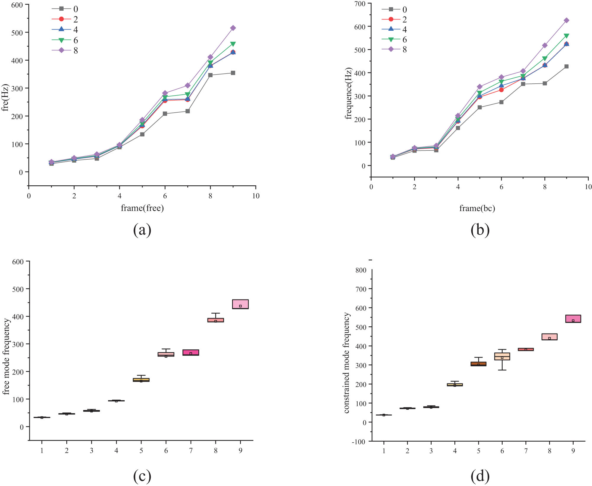
0–8 cross-ply prosthesis foot mode frequency. (a) Free mode frequency point line diagram. (b) Constrained mode frequency point line diagram. (c) Free mode frequency boxplot. (d) Constrained mode frequency boxplot.
In the free modal frequencies of the bionic foot of each layer, the frequencies from the first mode to the fourth mode increase slowly, the frequencies from the fourth mode to the sixth mode increase sharply, the frequencies of the sixth and seventh modes are similar, and the frequencies from the seventh to the ninth modes increase gradually.
The free mode frequencies of the bionic foot without cross-ply and the bionic foot with cross-ply have little difference in the first four steps, and the difference is obvious from the fifth to the eighth step. The changing trend of the mode frequencies of the bionic foot with cross-ply and the bionic foot without cross-ply is different from the eighth to the ninth step.
For the bionic foot with cross-ply, the first four free mode frequencies are similar, and the difference in natural frequencies increases from the fifth mode. The free mode frequencies of two cross-ply bionic foot and four cross-ply bionic foot are highly overlapped. With the increase in the number of cross-ply, the natural frequency of free mode increases.
The overall trend of the constrained modal frequency of each bionic foot is as follows: the frequency increases gently from the first-order constrained modal to the third-order constrained modal, sharply from the third-order to the fifth-order modal, slowly from the fifth- to the seventh-order modal, and sharply from the seventh- to the ninth-order constrained modal.
Compared with the bionic foot without a cross-ply, the constrained modal frequencies of the bionic foot with a cross-ply are higher than those of the bionic foot. There is little difference in the first three constrained modal frequencies of the bionic foot with various cross layers, but with the increase in modal order, the gap between the modal frequencies of the bionic foot with various layers increases.
Except for the sixth mode, the frequencies of the constrained modes of the bionic foot with a two-layer cross-ply and the bionic foot with a four-layer cross-ply are similar. The constrained modal frequency of the bionic foot increases with the increase in the number of attached cross plies. The frequency of the first three constrained modes increases slowly, and that of the fourth to ninth constrained modes increases with the increase in the number of cross plies.
With the increase in cross-ply, the natural frequency will increase, and the influence in orders 5–9 is greater than that in orders 1–4. There is no significant difference between two layers and four layers. The first three natural frequencies increase slowly, and the higher modes increase sharply. The natural frequencies of order 7 are similar.
The influence of cross-ply on the first three modes of constrained mode is less than that on the fourth to ninth modes. The difference in constrained mode frequencies between the second and fourth layers is small, and 4-6-8 increases gradually. The second and third modes have similar vibration frequencies. 5- to 7-order frequencies increase slowly, and other modal frequencies increase sharply with the increase in order.
This study has two limitations. The first limitation is that we cannot find enough peer-reviewed studies on the subject. Therefore, we used approximate test data from previous studies to verify the simulation model. The second limitation is cost constraints. Our funds are not enough to support us to design a special testing system to complete the testing of foot and ankle prosthetics, which somewhat weakens the convincing of the results. We will provide further data in subsequent studies.
4 Conclusions
A lattice sandwich bionic prosthetic foot is designed and simulated according to the ISO 10328 standard. The influence of cross-ply on the energy storage characteristics of the prosthetic foot is analyzed. The free modes and constrained modes of each cross-ply bionic prosthetic foot structure are calculated, respectively. The effects of cross-ply on modal shapes and natural frequencies are analyzed, leading to the identification of dangerous working conditions for the lattice sandwich bionic foot.
Overall, our findings show that the storage of strain energy increases with the rise of cross-ply under heel-strict working conditions, while the strain energy distribution increases with the increase in cross-ply under toe-off conditions. We also discovered that the dangerous modes of free mode are the first, third, and fifth modes, while the dangerous modes of constrained mode are the first, second, fifth, and ninth modes. Furthermore, we found that the natural frequencies of both free mode and constrained mode of the bionic foot increase with the increase in cross-ply, and that cross-ply and non-cross-ply have different effects on the free mode and constrained mode displacement of the foot.
The method we employed in this study can be applied to the optimization of ply for composite structures and to the study of the energy storage and vibration properties of prosthetic foot. Our results provide a valuable contribution to the development of prosthetic devices and offer insight into the potential for further research in this field.
-
Funding information: This research was funded by the Tianjin Postgraduate Research Innovation Project, grant number 2020YJSB065, Tianjin Science and Technology Plan Project, grant number [20JCYBJC01430], and the Tianjin Postgraduate Research Innovation Project, grant number [2019YJSB014].
-
Conflict of interest: Authors state no conflict of interest.
-
Data availability statement: The FE model data used to support the findings of this study are included in the article.
References
[1] Hassan J, O’Higgins RM, Feser T, Waimer M, McCarthy CT, Toso N, et al. Influence of layup, stacking sequence and loading rate on energy absorption of tension-absorber joints. Composite Struct. 2020;261:113327.10.1016/j.compstruct.2020.113327Suche in Google Scholar
[2] Pro JW, Barthelat F. Is the Bouligand architecture tougher than regular cross-ply laminates? A discrete element method study. Extreme Mech Lett. 2020;41:101042.10.1016/j.eml.2020.101042Suche in Google Scholar
[3] Rodrigues DE, Belinha J, Dinis LM, Jorge RN. The bending behaviour of antisymmetric cross-ply laminates using high-order shear deformation theories and a Radial Point Interpolation Method. Structures. 2021;32:1589–603.10.1016/j.istruc.2021.03.048Suche in Google Scholar
[4] Sasikumar A, Trias D, Costa J, Singery V, Linde PE. Mitigating the weak impact response of thin-ply based thin laminates through an unsymmetrical laminate design incorporating intermediate grade plies. Composite Struct. 2019;220:93–104.10.1016/j.compstruct.2019.03.069Suche in Google Scholar
[5] Fedon NC, Weaver PM, Pirrera A, Macquart T. A method using beam search to design the lay-ups of composite laminates with many plies. Composites Part C: Open Access. 2021;4:100072.10.1016/j.jcomc.2020.100072Suche in Google Scholar
[6] Yang J, Song B, Zhong XP, Jin P. Optimal design of blended composite laminate structures using ply drop sequence. Composite Struct. 2016;135:30–7.10.1016/j.compstruct.2015.08.101Suche in Google Scholar
[7] Arikoglu A, Ozturk AG. A novel approach for in-plane vibration and damping analysis of arbitrarily curved laminated composite and sandwich beams. Composite Struct. 2020;253:112781.10.1016/j.compstruct.2020.112781Suche in Google Scholar
[8] Xu G, Zeng T, Cheng S, Wang X, Zhang K. Free vibration of composite sandwich beam with graded corrugated lattice core. Composite Struct. 2019;229:111466.10.1016/j.compstruct.2019.111466Suche in Google Scholar
[9] Fazeli S, Stokes-Griffin C, Gilbert J, Compston P. An analytical solution for the vibrational response of stepped smart cross-ply laminated composite beams with experimental validation. Composite Struct. 2021;266:113823.10.1016/j.compstruct.2021.113823Suche in Google Scholar
[10] Zhang Y, Li Z, Xu K, Zang J. A lattice sandwich structure with the active variable stiffness device under aerodynamical condition. Aerosp Sci Technol. 2021;116:106849.10.1016/j.ast.2021.106849Suche in Google Scholar
[11] Xiao M, Xiliang L, Zhang Y, Gao L, Gao J, Chu S. Design of graded lattice sandwich structures by multiscale topology optimization. Computer Methods Appl Mech Eng. 2021;384:113949.10.1016/j.cma.2021.113949Suche in Google Scholar
[12] Ghannadpour SA, Mahmoudi M, Hossein Nedjad K. Structural behavior of 3D-printed sandwich beams with strut-based lattice core: experimental and numerical study. Composite Struct. 2021;281:115113.10.1016/j.compstruct.2021.115113Suche in Google Scholar
[13] He M, Li Y, Yin J, Sun Q, Xiong W, Li S, et al. Compressive performance and fracture mechanism of bio-inspired heterogeneous glass sponge lattice structures manufactured by selective laser melting. Mater Des. 2022;214:110396.10.1016/j.matdes.2022.110396Suche in Google Scholar
[14] Bai L, Yue X, Chen X, Xin L, Junfang Z, Li K, et al. Improved mechanical properties and energy absorption of Ti6Al4V laser powder bed fusion lattice structures using curving lattice struts. Materials Design. 2021;211:110140.10.1016/j.matdes.2021.110140Suche in Google Scholar
[15] Adamczyk PG, Roland M, Hahn ME. Novel method to evaluate angular stiffness of prosthetic feet from linear compression tests. J Biomech Eng. 2013;135(10):104502–5.10.1115/1.4025104Suche in Google Scholar PubMed PubMed Central
[16] Adamczyk PG, Roland M, Hahn ME. Sensitivity of biomechanical outcomes to independent variations of hindfoot and forefoot stiffness in foot prostheses. Hum Mov Sci. 2017;54:154–71.10.1016/j.humov.2017.04.005Suche in Google Scholar PubMed PubMed Central
[17] Fey NP, Klute GK, Neptune RR. The influence of energy storage and return foot stiffness on walking mechanics and muscle activity in below-knee amputees. Clin Biomech. 2011;26(10):1025–32.10.1016/j.clinbiomech.2011.06.007Suche in Google Scholar PubMed
[18] Fey NP, Klute GK, Neptune RR. Altering prosthetic foot stiffness influences foot and muscle function during below-knee amputee walking: a modeling and simulation analysis. J Biomech. 2013;46(4):637–44.10.1016/j.jbiomech.2012.11.051Suche in Google Scholar PubMed
[19] Klodd E, Hansen AH, Fatone S, Edwards ML. Effects of prosthetic foot forefoot flexibility on oxygen cost and subjective preference rankings of unilateral transtibial prosthesis users. J Rehabilitation Res Dev. 2010;47(6):543–52.10.1682/JRRD.2010.01.0003Suche in Google Scholar PubMed
[20] Klodd E, Hansen A, Fatone S, Edwards M. Effects of prosthetic foot forefoot flexibility on gait of unilateral transtibial prosthesis users. J Rehabilitation Res Dev. 2010;47(9):899–910. 10.1682/jrrd.2009.10.0166.Suche in Google Scholar PubMed
[21] Hamzah MN, Ghannadpour A. Design of a novel carbon-fiber ankle-foot prosthetic using finite element modeling. IOP Conference Series: Materials Science and Engineering; 2018. p. 433.10.1088/1757-899X/433/1/012056Suche in Google Scholar
[22] Jang TS, Lee JJ, Lee DH, Yoon Y. Systematic methodology for the design of a flexible keel for energy-storing prosthetic feet. Med Biol Eng Comput. 2006;39:56–64.10.1007/BF02345267Suche in Google Scholar PubMed
[23] Alleva S, Antonelli MG, Zobel PB, Durante F. Biomechanical design and prototyping of a powered ankle-foot prosthesis. Materials. 2020;13(24):5806.10.3390/ma13245806Suche in Google Scholar PubMed PubMed Central
[24] Contini R. Body Segment Parameters. Part II. Artif Limbs. 1972;16:1–19.Suche in Google Scholar
[25] Boresi AP, Schmidt RJ, Sidebottom OM. Advanced mechanics of materials. Vol. 6. New York: Wiley; 1993.Suche in Google Scholar
[26] Tang Y, Chen H, Ping X, Zhang Y. Mechanical properties of carbon fiber reinforced epoxy composite pyramid lattice sandwich prosthetic foot structure under vertical load. Acta Materiae Compositae Sin. 2021;38(3):797–808.Suche in Google Scholar
© 2023 the author(s), published by De Gruyter
This work is licensed under the Creative Commons Attribution 4.0 International License.
Artikel in diesem Heft
- Regular Articles
- Effects of cellulose nanofibers on flexural behavior of carbon-fiber-reinforced polymer composites with delamination
- Damage mechanisms of bismaleimide matrix composites under transverse loading via quasi-static indentation
- Experimental study on hydraulic fracture behavior of concrete with wedge-splitting testing
- The assessment of color adjustment potentials for monoshade universal composites
- Metakaolin-based geopolymers filled with volcanic fly ashes: FT-IR, thermal characterization, and antibacterial property
- The effect of temperature on the tensile properties and failure mechanisms of two-dimensional braided composites
- The influence of preparation of nano-ZrO2/α-Al2O3 gradient coating on the corrosion resistance of 316L stainless steel substrate
- A numerical study on the spatial orientation of aligning fibrous particles in composites considering the wall effect
- A simulative study on the effect of friction coefficient and angle on failure behaviors of GLARE subjected to low-velocity impact
- Impact resistance capacity and degradation law of epoxy-coated steel strand under the impact load
- Analytical solutions of coupled functionally graded conical shells of revolution
- The influence of water vapor on the structural response of asphalt pavement
- A non-invasive method of glucose monitoring using FR4 material based microwave antenna sensor
- Chloride ion transport and service life prediction of aeolian sand concrete under dry–wet cycles
- Micro-damage analysis and numerical simulation of composite solid propellant based on in situ tensile test
- Experimental study on the influence of high-frequency vibratory mixing on concrete performance
- Effects of microstructure characteristics on the transverse moisture diffusivity of unidirectional composite
- Gradient-distributed ZTAp-VCp/Fe45 as new anti-wear composite material and its bonding properties during composite casting
- Experimental evaluation of velocity sensitivity for conglomerate reservoir rock in Karamay oil field
- Mechanical and tribological properties of C/C–SiC ceramic composites with different preforms
- Mechanical property improvement of oil palm empty fruit bunch composites by hybridization using ramie fibers on epoxy–CNT matrices
- Research and analysis on low-velocity impact of composite materials
- Optimizing curing agent ratios for high-performance thermosetting phthalonitrile-based glass fibers
- Method for deriving twisting process parameters of large package E-glass yarn by measuring physical properties of bobbin yarn
- A probability characteristic of crack intersecting with embedded microcapsules in capsule-based self-healing materials
- An investigation into the effect of cross-ply on energy storage and vibration characteristics of carbon fiber lattice sandwich structure bionic prosthetic foot
- Preparation and application of corona noise-suppressing anti-shedding materials for UHV transmission lines
- XRD analysis determined crystal cage occupying number n of carbon anion substituted mayenite-type cage compound C12A7: nC
- Optimizing bending strength of laminated bamboo using confined bamboo with softwoods
- Hydrogels loaded with atenolol drug metal–organic framework showing biological activity
- Creep analysis of the flax fiber-reinforced polymer composites based on the time–temperature superposition principle
- A novel 3D woven carbon fiber composite with super interlayer performance hybridized by CNT tape and copper wire simultaneously
- Effect of aggregate characteristics on properties of cemented sand and gravel
- An integrated structure of air spring for ships and its strength characteristics
- Modeling and dynamic analysis of functionally graded porous spherical shell based on Chebyshev–Ritz approach
- Failure analysis of sandwich beams under three-point bending based on theoretical and numerical models
- Study and prediction analysis on road performance of basalt fiber permeable concrete
- Prediction of the rubberized concrete behavior: A comparison of gene expression programming and response surface method
- Study on properties of recycled mixed polyester/nylon/spandex modified by hydrogenated petroleum resin
- Effect of particle size distribution on microstructure and chloride permeability of blended cement with supplementary cementitious materials
- In situ ligand synthesis affording a new Co(ii) MOF for photocatalytic application
- Fracture research of adhesive-bonded joints for GFRP laminates under mixed-mode loading condition
- Influence of temperature and humidity coupling on rutting deformation of asphalt pavement
- Review Articles
- Sustainable concrete with partial substitution of paper pulp ash: A review
- Durability and microstructure study on concrete made with sewage sludge ash: A review (Part Ⅱ)
- Mechanical performance of concrete made with sewage sludge ash: A review (Part Ⅰ)
- Durability and microstructure analysis of concrete made with volcanic ash: A review (Part II)
- Communication
- Calculation of specific surface area for tight rock characterization through high-pressure mercury intrusion
- Special Issue: MDA 2022
- Vibration response of functionally graded material sandwich plates with elliptical cutouts and geometric imperfections under the mixed boundary conditions
- Analysis of material removal process when scratching unidirectional fibers reinforced polyester composites
- Tailoring the optical and UV reflectivity of CFRP-epoxy composites: Approaches and selected results
- Fiber orientation in continuous fiber-reinforced thermoplastics/metal hybrid joining via multi-pin arrays
- Development of Mg-based metal matrix biomedical composites for acicular cruciate ligament fixation by reinforcing with rare earth oxide and hydroxyapatite – A mechanical, corrosion, and microstructural perspective
- Special Issue: CACMSE
- Preparation and application of foamed ceramic panels in interior design