Analytical solutions of coupled functionally graded conical shells of revolution
-
Aleksander Muc
 and
Małgorzata Muc-Wierzgoń
and
Małgorzata Muc-Wierzgoń

Abstract
In this article, axisymmetric deformations of coupled functionally graded conical shells are studied. The analytical solution is presented by using the complex hypergeometric and Legendre polynomial series. The presented results agree closely with reference results for isotropic conical shells of revolution. The symbolic package Mathematica commands is added to the article to help readers search for particular solutions. The detailed solutions to two problems are discussed, i.e. the shells subjected to axisymmetric pressure or to edge loadings. The influence of material property effects is characterized by a multiplier characterizing an unsymmetric shell wall construction (stiffness coupling). The results can be easily adopted in design procedures.
Nomenclature
Symbols
Greek
- α
-
half vertex of the conical shell
- φ
-
meridional coordinate
- θ
-
circumferential coordinate
- ε
-
membrane strain
- κ
-
the change in curvature
- ν
-
the Poisson ratio of FGMs
- μ
-
the parameter defining the unsymmetry of the wall construction
Latin
- A
-
the membrane component of the stiffness matrix for FGMs
- ALam
-
Lame parameter along the meridian
- A rs
-
the membrane components of the stiffness matrix
- B
-
the bending-membrane component of the stiffness matrix for FGMs
- BLam
-
Lame parameter along the circumference
- B rs
-
the bending-membrane components of the stiffness matrix
- D
-
the bending component of the stiffness matrix for FGMs
- D rs
-
the bending components of the stiffness matrix
- E
-
the Young modulus of FGMs
- h
-
the thickness of the shell
- i
-
=
- Im
-
the imaginary part of the complex variable
- J
-
the Bessel function
- L
-
the differential operator
- L Q, L P
-
the Legendre polynomials
- M r
-
the moment resultants
- N r
-
the membrane stress resultants
- n
-
the material power-law index
- q
-
the normal pressure
- [Q]
-
the matrix representation of the stiffness matrix
- r
-
radius of parallel circular of the conical shell
- R 1
-
principal radius of the meridian
- R 2
-
principal radius of the circumference
- Re
-
the real part of the complex variable
- s
-
coordinate along the generator of the conical shell
- S 1, S 2, S 3, S 4
-
the particular solutions
- T
-
the transverse shear force
- u
-
displacement in the meridional direction to the shell cross-section
- w
-
displacement in the normal direction to the shell cross-section
- Y
-
the modified Bessel function
- (zt)
-
the distance measured along the normal to the shell mid-surface
Subscripts
- b
-
the bottom surface of FGMs
- t
-
the top surface of FGMs
- r,s
-
= 1 or 2 (equivalent to φ or θ)
Superscripts
- n
-
the power-law index
- c, p
-
the complementary (F = 0) and particular (F ≠ 0) solutions
1 Introduction
The invention, conception, and manufacturing of functionally graded materials (FGMs) introduce a new class of composite materials that should be considered in the investigations of structural behaviour and their response to loading and boundary conditions (Figure 1).

FGM categories. (a) Continuous gradients and (b) discontinuous gradients.
For discontinuous gradients three types of gradients are introduced: 1) gradient composition, 2) gradient microstructure, and 3) gradient porosity.
For FGMs the review of possible compositions of materials is discussed in previous studies [1–4].
It is necessary to underline that the analysis of structures made of FGMs can be divided into the following areas:
The derivations of the structural response understood in the sense of deformations, buckling loads, or free vibrations can be carried out in different ways, i.e. analytical, the Rayleigh–Ritz method, and the Bubnov–Gallerkin method or finite difference method called as the generalized differential quadrature method. However, due to the material behaviour plotted in Figure 1, as far as the author is concerned, there are no finite element (FE) commercial packages that allow the analysis of the structural configuration plotted in Figure 1. In general, it is necessary to introduce hierarchical formulation for 3-D structures or to divide the construction to 15–20 or more FEs in the thickness direction to characterize variable material configuration in 2-D approach.
In general, two different forms of conical shells can be considered (Figure 2). In addition, shallow conical shells that are conical segments can also be analysed.

Forms of conical shells. (a) Complete shell and (b) truncated shell.
The present work is devoted to the formulations and analytical solutions for axi-symmetric conical shells to illustrate the differences and similarities between functionally graded and isotropic conical structures. It should be mentioned that it is possible to also investigate conical shells made of laminates or nanostructures in the identical way as shown in the study of Muc and Muc-Wierzgoń [44]. These problems have not been addressed in this article and will be the objectives of future works.
The analytical description of axisymmetric isotropic shells of revolution is demonstrated in monographs [45,46,47]. Galletly and Muc [48,49] and Muc [33] studied buckling and deformations of laminated shells of revolution considering symmetric configurations only. Due to coupling effects between membrane and bending stress resultants, the analysis of arbitrarily laminated shells was usually carried out using numerical methods, e.g. Czebyshev expansions [50] or power series expansions [51,52].
Although a great number of works had been carried out for static analysis of axisymmetric shells using isotropic and laminated materials a general lack of information for axisymmetric structures made of FGMs is observed. As it is pointed out by Moita et al. [40], few works are found in the literature, and most of them are related to cylinders, circular, and annular plates solved using numerical methods.
The aim of this article is to demonstrate analytical solutions for axi-symmetric conical shells made of FGM and subjected to the normal uniform pressure. The solutions are obtained using Bessel functions and compared with the available published results for isotropic shells. The influence of coupling effects on shell deformations is studied in detail.
2 Formulation of the problem
The shells of revolution can be defined in the curvilinear orthogonal coordinates φ and θ of a point on the shell mid-surface. It is convenient to take the spherical coordinates, where the angle φ defines the location of a point along the meridian and θ describes the location of a point along the parallel circle – the circumferential coordinate (Figure 1). R 1 = R 1(φ) is the principal radius of the meridian and R 2 = R 2(φ) is the principal radius of the parallel circle. Let us note that r = R 2sin(φ) and the Lame parameters are defined as follows: ALam = R 1, BLam = r.
When an arbitrary shell of revolution is subjected to rotationally symmetrical loads, its deformations and stress resultants and couples do not depend upon the circumferential variable θ. The axisymmetric deformations of shells of revolution are described by two displacement components of the shell mid-surface u and w in the meridional and normal directions to the shell cross-section, respectively (Figure 3).

Cross-section of an axisymmetric shell of revolution.
For shells of revolution under axi-symmetrical loads the strain displacement equations take the following form:
where ε denotes the membrane strain, κ represents the change in curvature, and 1 and 2 correspond to the meridional φ and circumferential directions θ, respectively. The constitutive equations are written as follows:
where
The terms N r and M r represent the stress resultants and moment resultants, respectively. The variation in elastic modulus E characterizes the distribution of porosity along the thickness direction z and is defined as follows:
where the symbols t and b refer to the material properties on the top and bottom surfaces, n is power index, and ν is the Poisson’s ratio.
To complete the set of fundamental equations we add the equilibrium equations derived using principle of virtual work [45,46,47]:
where T denotes the transverse shear force, and q is the normal pressure on the shell mid-surface.
Using the classical Meisner approach to the analysis of axisymmetric shell deformations [45,46,47], the fundamental equations can be reduced to the system of two differential equations for two variables β and U = R 2 T being the functions of the meridional coordinate φ:
where prime over the symbols denotes the differentiation with respect to φ variable and
where φ e is a coordinate of the shell edge and the constant C characterize an axial coordinate of the external load applied at the top edge. Inserting that the couple term B = 0, equations (7) and (8) are reduced to the classical equations for isotropic axisymmetric shells.
Equations (7) and (8) can be rewritten in a more compact form as follows:
where A = A 11, B = B 11, D = D 11.
If the radius of the shell curvature R 1, the shell thickness t, the Young’s modulus E, and the Poisson ratio ν are constant, equations (7), (8), (10), and (11) can be reduced to the following complementary differential equations (the symbol c denotes that F = 0 – equation (9)):
Each of the equations has complex solutions as AD > B 2. If the coupling term B tends to 0, the above relation describes the deformations of isotropic axisymmetric shells.
3 Solution of governing relation for axi-symmetric conical shells
For conical shells the generators of the mid-surface are straight and so it is appropriate to change the variables introducing ds = R 1dφ (compare Figure 3 with Figure 4). Replacing the variable φ with the variable s in equations (7), (8), (10), and (11), we introduce the following relationships:
where φ is the constant along the shell meridian and R 1 does not vary with the s variable. The generators are inclined at an angle α with the axis of symmetry – φ = π/2 – α. Let us note that the curvature 1/R 1 tends to 0. The equations correspond to those for cylindrical shells as α = 0.

Geometry of a conical shell.
In addition, let us examine deformations of conical shells having the constant thickness, i.e. t(s) = const. Setting R 1 → ∞ and using relation (13), the system of equations (7), (8), (10), and (11) is reduced to the following form (F(φ) = 0):
Let us note that inserting B = 0, the equations (14) and (15) are reduced to the classical Meisner equations for isotropic shells.
Elimination of each variable (T or β) in equations (14) and (15) leads to fourth-order differential equations, i.e.:
Each of the equations (7), (8), (10), and (11) can be solved for one of the dependent variables. The solutions can be represented in the following way:
where the superscripts c and p denote the complementary (F = 0) and particular (F ≠ 0) solutions, respectively. The complementary solutions satisfy the following relation:
Making the transformation of variables
where S i are the real functions. The solutions W i are represented by the Kelvin functions:
where J 2 is the second-order Bessel function of the first kind, and Y 2 is the second-order modified Bessel function of the second kind. They can be found easily by the single Mathematica command DSolve. Finally, the complementary solution of equation (20) can be expressed as:
For FGM conical shells the deformation functions are controlled by the value of the parameter μ 2 in equation (20). For isotropic shells this value is the function of the ratio 1/t
but for FGM shells it is also the function of the coupling effects expressed by the term B – equation (20). Figure 5 illustrates the influence of the coupling effects on the variations of the parameter μ 2. It is represented by two values: the ratio E t/E b and the porosity index n – equation (5).

Variations of the dimensionless controlling parameter
The computations of the complementary solutions for the kinematic parameter β c can also be found in the analytical way using equation (7):
Then, from the equilibrium equation (6) one can obtain the analytical form of the stress resultants
Finally, the kinematic complementary displacements u c and w c can be derived in the closed analytical way using the relation (26), the fundamental definitions in equations (1) and (2), and the constitutive relation (3):
The computations can be made easily applying the symbolic packages, e.g. Mathematica.
It is necessary to distinguish two classes of problems (Figure 2) that should be introduced independently, referred directly to the convenience and simplicity of analytical solutions. For shells closed at the apex (Figure 2a). singularity occurs at φ = 0. Shells opened at the apex always have the convergent solutions (Figure 2b). It is necessary to point out that analytical solutions (19) are always expressed by real functions.
3.1 Shells closed at the apex
The solutions for equation (17) are presented in the handbook [53]. The change of variables,
leads to the following hypergeometric equation [3]:
Comparing the above relation to a standard form of the Gaussian hypergeometric equation one can find that:
where
and F(a,b,c,x) is a hypergeometric function. Two additional solutions S 3 and S 4 are singular at the shell apex and they would have to be suppressed [46].
Comparing the complementary solutions for isotropic and FGM shells (Figures 6 and 7) one can observe the effects of the
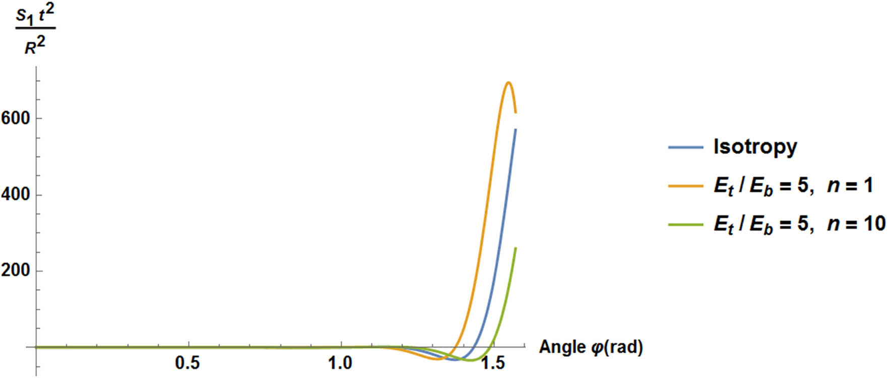
Solution function S 1 for FGM conical shells.

Solution function S 2 for FGM conical shells.
Further analysis of particular problems is reduced to finding the solutions for shells having the particular loading and boundary conditions and in this way to search for particular solutions T p and β p (equation (16)).
3.2 Shells opened at the apex
The general analytical solution of equations (14) and (15) can be found using the Mathematica package, i.e.:
where the symbol mi corresponds to μ 2 in equation (16), c1 and c2 are complex constants of integration, and LegendreP and LegendreQ denote Legendre polynomials singular at φ = 0. The above relation represents the analytical solution that can be easily transformed to the relation (17). Inserting the specific form of the external loading Φ(φ), it is possible to derive also the analytical form of the particular solutions of the governing equations in the closed compact manner.
4 Conical shells under uniform external pressure
Let us consider the case of the conical shell loaded by the uniform external pressure q and clamped at the edge φ = π/2:
With this value the particular solutions:
since equations (14) and (15) are homogeneous. However, the effects of the distributed load q is brought by the equilibrium equation (6), i.e.:
The stress resultants can be derived from the equilibrium conditions (26) and the equations (30) and (32)–(34):
Using the above equations and the definitions (2) and (3) and the relation (7), the stress couples can be written in the following way:
Inserting the coupling stiffness B = 0, one can find the equations (35)–(37) for isotropic shells [45,46]. The symbols P 1 and P 2 are integration constants and for the boundary conditions in equation (32) are equal to:
Figure 8 demonstrates the distributions of the dimensionless bending moments M φ /(qt 2) along the shell meridian. The results demonstrate the localized effects at the clamped edge that increase with the decrease of the thickness ratio. The coupling effects expressed by the controlling parameter μ 2 in equation (17) have a significant influence on the values of the bending moments at the clamped edge – the growth of this value results in the increase of bending effects.
Similar results to those plotted in Figure 8 can be obtained using equations (35)–(38). However, the distributions of the stress resultants N φ show that these values are almost equal to 0.5qR (the membrane state).

Distributions of the dimensionless bending moments M φ .
5 Conical shells subjected to edge loadings
Let us consider the deformations of conical shells subjected to the edge loads in the form of bending moments M and edge forces H as illustrated in Figure 9.

Edge loadings.
Using the Legendre polynomial solutions described in Section 3.3 one can evaluate the distributions of meridional dimensionless bending moments (Figure 10). The curves represent the stress concentrations near the shell bottom edge. As it may be seen the unsymmetry of the shell wall construction (FGMs) results in the increase of the maximal bending moments. The influence of FGMs is nonlinear. As it is noticed by Kraus [46] the extension of the peaks in each curve is approximately equal to 2.8π.
![Figure 10
Distributions of bending moments – φ = 60°, s
1 = 100 [mm], s
2 = 300 [mm], and R
θ
= s
2
ctg(φ) = 1,730 [mm].](/document/doi/10.1515/secm-2022-0183/asset/graphic/j_secm-2022-0183_fig_010.jpg)
Distributions of bending moments – φ = 60°, s 1 = 100 [mm], s 2 = 300 [mm], and R θ = s 2 ctg(φ) = 1,730 [mm].
6 The Geckeler approximation
Geckeler [54] proposed to reduce the equations (14) and (15) to the following form:
Differentiating twice each of equations (40) or (41) the problem is reduced to fourth-order differentiating equation.
Equation (41) demonstrates explicitly the effects of the unsymmetry of the wall construction due to the form of FGMs – equation (16).
Biderman [55] proved the convenience of the Geckeler solutions to the edge-effect problems discussed in the previous section. The difference between accurate and simplified solutions does not exceed 1%.
Cui et al. [56] formulated the approximations of the solutions for conical shells loaded by pressure.
7 Final remarks
The presented analytical solutions herein demonstrate evidently the significant influence of the coupling bending-membrane terms of the stiffness matrix illustrating the unsymmetry in the construction of shell walls of porous FGMs. Those effects are characterized by the controlling parameter μ. It is worth to mention that the similar controlling parameter is proposed and introduced in the description of flutter problems for structures made of FGMs or plates reinforced by nanostructures (nanoplates or nanotubes) – see the study of Muc and Muc-Wierzgoń [44].
Let us note that the distributions of the stress resultants and bending moments are sensitive to the variations of the thickness ratio t/R. In the present work, the classical Love–Kirchhoff hypothesis is used, but for thicker structures (the thickness-to-radius ratio >0.1) the higher order 2-D shell theories should be used, e.g. in the form proposed in the Appendix of the work in the study of Muc and Muc-Wierzgoń [44].
The present results are derived for conical shells; however, the identical analysis can be easily extended to the analysis of shells or pressure vessels having various forms – paraboloidal, hyperbolical, elliptical, and torispherical discussed from the numerical and optimization point of view, e.g. in the study of Moita et al. [40].
References
[1] Bhavar V, Kattire P, Thakare S, Singh RK. A review on functionally gradient materials (FGMs) and their applications. IOP Conf Ser Mater Sci Eng. 2017;229(1):012021.10.1088/1757-899X/229/1/012021Search in Google Scholar
[2] Mohammadi M, Rajabi M, Ghadiri M. Functionally graded materials (FGMs): A review of classifications, fabrication methods and their applications. Process Appl Ceram. 2021;15(4):319–43.10.2298/PAC2104319MSearch in Google Scholar
[3] Verma RK, Parnagiha D, Chopkar M. A review on fabrication and characteristics of functionally graded aluminum composites fabricated by centrifugal casting method. SN Appl Sci. 2021;3:227.10.1007/s42452-021-04200-8Search in Google Scholar
[4] Miyamoto Y, Kaysser WA, Rabin BH, Kawasaki A, Ford RG. Functionally graded materials: Design, processing, and applications. Manhattan, NY, USA: Springer; 1999.10.1007/978-1-4615-5301-4Search in Google Scholar
[5] Reddy JN. Analysis of functionally graded plates. Int J Numer Methods Eng. 2000;47:663–84.10.1002/(SICI)1097-0207(20000110/30)47:1/3<663::AID-NME787>3.0.CO;2-8Search in Google Scholar
[6] Wu CP, Chiu KH, Wang YM. A review on the three-dimensional analytical approaches of multilayered and functionally graded piezoelectric plates and shells. CMC-Comput Mater Continua. 2008;8:93–132.Search in Google Scholar
[7] Shen HS. Functionally Graded Materials: Nonlinear Analysis of Plates and Shells. BocaRaton, FL, USA: CRC Press; 2009.Search in Google Scholar
[8] Wang Y, Xu R, Ding H. Three-dimensional solution of axi-symmetric bending of functionally graded circular plates. CompositeStructures. 2010;92:1683–93.10.1016/j.compstruct.2009.12.002Search in Google Scholar
[9] Liew KM, Ferreira AJM. A review of meshless methods for laminated and functionally graded plates and shells. Compos Struct. 2011;93:2013–41.10.1016/j.compstruct.2011.02.018Search in Google Scholar
[10] Aghdam MM, Shahmansouri N, Bigdeli K. Bending analysis of moderately trick functionally graded conical panels. Compos Struct. 2011;93:1376–84.10.1016/j.compstruct.2010.10.020Search in Google Scholar
[11] Jha DK, Kant T, Singh RK. A critical review of recent research on functionally graded plates. Compos Struct. 2013;96:833–49.10.1016/j.compstruct.2012.09.001Search in Google Scholar
[12] Tornabene F, Viola E. Static analysis of functionally graded doubly-curved shells and panels of revolution. Meccanica. 2013;48:901–30.10.1007/s11012-012-9643-1Search in Google Scholar
[13] Abediokhchi J, Shakouri M, Kouchakzadeh MA. Bending analysis of moderately thick functionally graded conical panels with various boundary conditions using GDQ method. Compos Struct. 2013;103:68–74.10.1016/j.compstruct.2013.03.022Search in Google Scholar
[14] Viola E, Rossetti L, Fantuzzi N, Tornabene F. Static analysis of functionally graded conical shells and panels using the generalized unconstrained third order theory coupled with the stress recovery. Compos Struct. 2014;112:44–65.10.1016/j.compstruct.2014.01.039Search in Google Scholar
[15] Thai HT, Kim SE. A review of theories for the modeling and analysis of functionally graded plates and shells. Compos Struct. 2015;128:70–86.10.1016/j.compstruct.2015.03.010Search in Google Scholar
[16] Wu CP, Liu YC. A review of semi-analytical numerical methods for laminated composite and multilayered functionally graded elastic/piezoelectric plates and shells. Compos Struct. 2016;147:1–15.10.1016/j.compstruct.2016.03.031Search in Google Scholar
[17] Sayyad AS, Ghugal YM. Modeling and analysis of functionally graded sandwich beams: A review. Mech Adv Mater Struct. 2019;26:1776–95.10.1080/15376494.2018.1447178Search in Google Scholar
[18] Flis J, Muc A. Influence of coupling effects on analytical solutions of functionally graded (FG) spherical shells of revolution. RAMS. 2021;60:761–70.10.1515/rams-2021-0064Search in Google Scholar
[19] Tornabene F. Free vibration analysis of functionally graded conical, cylindrical shell and annular plate structures with a four-parameter power-law distribution. Comput Methods Appl Mech Eng. 2009;198:2911–35.10.1016/j.cma.2009.04.011Search in Google Scholar
[20] Swaminathan K, Naveenkumar DT, Zenkour AM, Carrera E. Stress, vibration and buckling analyses of FGM plates-A state-of-the-art review. Compos Struct. 2015;120:10–31.10.1016/j.compstruct.2014.09.070Search in Google Scholar
[21] Punera D, Kant T. A critical review of stress and vibration analyses of functionally graded shell structures. Compos Struct. 2019;210:787–809.10.1016/j.compstruct.2018.11.084Search in Google Scholar
[22] Muc A, Flis J, Augustyn M. Optimal design of plated/shell structures under flutter constraints - a literature review. Materials. 2019;12:4215.10.3390/ma12244215Search in Google Scholar PubMed PubMed Central
[23] Muc A. Transverse shear effects in supersonic flutter problems for composite multilayered rectangular plates - Benchmark for numerical analysis. Compos Part C. 2020;1:100001.10.1016/j.jcomc.2020.100001Search in Google Scholar
[24] Muc A. Triangular functionally graded porous moderately thick plates – Deformations and free vibrations. J Comp Sci. 2021;5(10):342–51.10.3390/jcs5100276Search in Google Scholar
[25] Muc A, Flis J. Flutter characteristics and free vibrations of rectangular functionally graded porous plates. Compos Struct. 2021;261:113301.10.1016/j.compstruct.2020.113301Search in Google Scholar
[26] Alipour MM, Shariyat M. Semi-analytical buckling analysis of heterogeneous variable thickness viscoelastic circular plates on elastic foundations. Mech Res Commun. 2011;38:594–601.10.1016/j.mechrescom.2011.09.001Search in Google Scholar
[27] Alipour MM, Shariyat M. Semi-analytical solution for buckling analysis of variable thickness two-directional functionally graded circular plates with non-uniform elastic foundations. ASCE J Eng Mech. 2013;139:664–76.10.1061/(ASCE)EM.1943-7889.0000522Search in Google Scholar
[28] Shariyat M, Asemi K. 3D B-spline finite element nonlinear elasticity buckling analysis of rectangular FGM plates under non-uniform edge loads, using a micromechanical model. Compos Struct. 2014;112:397–408.10.1016/j.compstruct.2014.02.005Search in Google Scholar
[29] Sofiyev AH. On the dynamic buckling of truncated conical shells with functionally graded coatings subject to a time dependent axial load in the large deformation. Compos Part B. 2014;58:524–33.10.1016/j.compositesb.2013.10.013Search in Google Scholar
[30] Dung DV, Hoa LK, Thuyet BT, Nga NT. Buckling analysis of functionally graded material (FGM) sandwich truncated conical shells reinforced by FGM stiffeners filled inside by elastic foundation. Appl Math Mech – Engl Ed. 2016;37:879–902.10.1007/s10483-016-2097-9Search in Google Scholar
[31] Sofiyev AH. The buckling and vibration analysis of coating-FGM-substrate conical shells under hydrostatic pressure with mixed boundary conditions. Compos Struct. 2019;209:686–93.10.1016/j.compstruct.2018.10.104Search in Google Scholar
[32] Sofiyev AH. Review and the research on the vibration and buckling of the FGM conical shells. Compos Struct. 2019;211:301–17.10.1016/j.compstruct.2018.12.047Search in Google Scholar
[33] Muc A. On the buckling of composite shells of revolution under external pressure. Compos Struct. 1992;21(2):107–19.10.1016/0263-8223(92)90046-FSearch in Google Scholar
[34] Reddy JN, Chin CD. Thermo-mechanical analysis of functionally graded cylinders and plates. J Therm Stresses. 1998;21:593–626.10.1080/01495739808956165Search in Google Scholar
[35] Pelletier JL, Vel SS. An exact solution for the steady-state thermo-elastic response of functionally graded orthotropic cylindrical shells. Int J Solids Struct. 2006;43:1131–58.10.1016/j.ijsolstr.2005.03.079Search in Google Scholar
[36] Sofiyev AH. Thermo-elastic stability of functionally graded truncated conical shells. Compos Struct. 2007;77:56–65.10.1016/j.compstruct.2005.06.004Search in Google Scholar
[37] Wu Z, Chen W, Ren X. Refined global–local higher-order theory for angle-ply laminated plates under thermo-mechanical loads and finite element model. Compos Struct. 2009;88:643–58.10.1016/j.compstruct.2008.06.011Search in Google Scholar
[38] Golmakani ME, Kadkhodayan M. An investigation into the thermo-elastic analysis of circular and annular functionally graded material plates. Mech Adv Mater Struct. 2014;21:1–13.10.1080/15376494.2012.677101Search in Google Scholar
[39] Hao YX, Niu Y, Zhang W, Liu SB, Yao MH, Wang AW. Supersonic flutter analysis of shallow FGM conical panel accounting for thermal effects. Meccanica. 2018;53:95–109.10.1007/s11012-017-0715-0Search in Google Scholar
[40] Moita JS, Mota Soares CM, Carlos A, Mota Soares CM, Ferreira AJM. Elasto-plastic and nonlinear analysis of functionally graded axi-symmetric shell structures under thermal environment, using a conical frustum finite element model. Compos Struct. 2019;226:111186.10.1016/j.compstruct.2019.111186Search in Google Scholar
[41] Shariya MT, Alipour MM. Analytical bending and stress analysis of variable thickness FGM auxetic conical/cylindrical shells. LAJSS. 2017;14:805–43.10.1590/1679-78253413Search in Google Scholar
[42] Muc A. Evolutionary design of engineering constructions. LAJSS. 2018;15(4):e87, 21. 10.1590/1679-78254947.Search in Google Scholar
[43] Muc A. Optimizing the thickness/stiffness distribution optimization of infinitely wide porous FGM plates subjected to supersonic flutter constraints. Mech Compos Mater. 2021;56:713–20.10.1007/s11029-021-09917-6Search in Google Scholar
[44] Muc A, Muc-Wierzgoń M. Effects of material constructions on supersonic flutter characteristics for composite rectangular plates reinforced with carbon nano-structures. Sci Eng Compos Mater. 2021;28:107–15.10.1515/secm-2021-0010Search in Google Scholar
[45] Flügge W. Stresses in shells. Berlin-Heidelberg: Springer-Verlag; 1962.Search in Google Scholar
[46] Kraus H. Thin elastic shells. New York: John Wiley and Sons; 1967.Search in Google Scholar
[47] Mazurkiewicz ZE, Nagórski RT. Shells of revolution. PWN Warszawa. Amsterdam: Elsevier; 1991.Search in Google Scholar
[48] Galletly GD, Muc A. Buckling of fibre-reinforced plastic-steel torispherical shells under external pressure. Proc Inst Mech Eng Part C: J Mech Eng Sci. 1988;202(6):409–20.10.1243/PIME_PROC_1988_202_143_02Search in Google Scholar
[49] Galletly GD, Muc A. Buckling of externally pressurized composite torispherical domes. Proc Inst Mech Eng Part E: J Process Mech Eng. 1989;203(1):41–56.10.1243/PIME_PROC_1989_203_187_02Search in Google Scholar
[50] El-Nady AO, Negm HM. Analysis of arbitrarily laminated composite spherical shells by Chebyshev series. J Eng Appl Sci. 2004;51(4):777–94.Search in Google Scholar
[51] Muc A. Mechanics of Fibrous Composites, Wydawnictwo “Księgarnia Akademicka”, Kraków; 2003 (in Polish).Search in Google Scholar
[52] Fantuzzi N, Brischetto S, Tornabene F, Viola E. 2D and 3D shell models for the free vibration investigation of functionally graded cylindrical and spherical panels. Compos Struct. 2016;154:573–90.10.1016/j.compstruct.2016.07.076Search in Google Scholar
[53] Polyanin AD, Zaitsev VF. Handbook of exact solutions for ordinary differential equations. Boca Raton: Chapman & Hall CRC; 2003.10.1201/9781420035339Search in Google Scholar
[54] Geckeler J. Uber die Festigkeit Achsensymmetrischer Schalen, Forschg.-Arb. Ingwes, Berlin; 1926. p. 276.Search in Google Scholar
[55] Biderman VL. Mechanics of Thin-Walled Structures, Izd. Mashinostroenie, Moscow; 1977 (in Russian).Search in Google Scholar
[56] Cui. W, Pei, W, Zhang, W. A simple and accurate solutions of for calculating stresses in conical structures. Comput Struct. 2001;70:265–79.10.1016/S0045-7949(00)00139-5Search in Google Scholar
© 2023 the author(s), published by De Gruyter
This work is licensed under the Creative Commons Attribution 4.0 International License.
Articles in the same Issue
- Regular Articles
- Effects of cellulose nanofibers on flexural behavior of carbon-fiber-reinforced polymer composites with delamination
- Damage mechanisms of bismaleimide matrix composites under transverse loading via quasi-static indentation
- Experimental study on hydraulic fracture behavior of concrete with wedge-splitting testing
- The assessment of color adjustment potentials for monoshade universal composites
- Metakaolin-based geopolymers filled with volcanic fly ashes: FT-IR, thermal characterization, and antibacterial property
- The effect of temperature on the tensile properties and failure mechanisms of two-dimensional braided composites
- The influence of preparation of nano-ZrO2/α-Al2O3 gradient coating on the corrosion resistance of 316L stainless steel substrate
- A numerical study on the spatial orientation of aligning fibrous particles in composites considering the wall effect
- A simulative study on the effect of friction coefficient and angle on failure behaviors of GLARE subjected to low-velocity impact
- Impact resistance capacity and degradation law of epoxy-coated steel strand under the impact load
- Analytical solutions of coupled functionally graded conical shells of revolution
- The influence of water vapor on the structural response of asphalt pavement
- A non-invasive method of glucose monitoring using FR4 material based microwave antenna sensor
- Chloride ion transport and service life prediction of aeolian sand concrete under dry–wet cycles
- Micro-damage analysis and numerical simulation of composite solid propellant based on in situ tensile test
- Experimental study on the influence of high-frequency vibratory mixing on concrete performance
- Effects of microstructure characteristics on the transverse moisture diffusivity of unidirectional composite
- Gradient-distributed ZTAp-VCp/Fe45 as new anti-wear composite material and its bonding properties during composite casting
- Experimental evaluation of velocity sensitivity for conglomerate reservoir rock in Karamay oil field
- Mechanical and tribological properties of C/C–SiC ceramic composites with different preforms
- Mechanical property improvement of oil palm empty fruit bunch composites by hybridization using ramie fibers on epoxy–CNT matrices
- Research and analysis on low-velocity impact of composite materials
- Optimizing curing agent ratios for high-performance thermosetting phthalonitrile-based glass fibers
- Method for deriving twisting process parameters of large package E-glass yarn by measuring physical properties of bobbin yarn
- A probability characteristic of crack intersecting with embedded microcapsules in capsule-based self-healing materials
- An investigation into the effect of cross-ply on energy storage and vibration characteristics of carbon fiber lattice sandwich structure bionic prosthetic foot
- Preparation and application of corona noise-suppressing anti-shedding materials for UHV transmission lines
- XRD analysis determined crystal cage occupying number n of carbon anion substituted mayenite-type cage compound C12A7: nC
- Optimizing bending strength of laminated bamboo using confined bamboo with softwoods
- Hydrogels loaded with atenolol drug metal–organic framework showing biological activity
- Creep analysis of the flax fiber-reinforced polymer composites based on the time–temperature superposition principle
- A novel 3D woven carbon fiber composite with super interlayer performance hybridized by CNT tape and copper wire simultaneously
- Effect of aggregate characteristics on properties of cemented sand and gravel
- An integrated structure of air spring for ships and its strength characteristics
- Modeling and dynamic analysis of functionally graded porous spherical shell based on Chebyshev–Ritz approach
- Failure analysis of sandwich beams under three-point bending based on theoretical and numerical models
- Study and prediction analysis on road performance of basalt fiber permeable concrete
- Prediction of the rubberized concrete behavior: A comparison of gene expression programming and response surface method
- Study on properties of recycled mixed polyester/nylon/spandex modified by hydrogenated petroleum resin
- Effect of particle size distribution on microstructure and chloride permeability of blended cement with supplementary cementitious materials
- In situ ligand synthesis affording a new Co(ii) MOF for photocatalytic application
- Fracture research of adhesive-bonded joints for GFRP laminates under mixed-mode loading condition
- Influence of temperature and humidity coupling on rutting deformation of asphalt pavement
- Review Articles
- Sustainable concrete with partial substitution of paper pulp ash: A review
- Durability and microstructure study on concrete made with sewage sludge ash: A review (Part Ⅱ)
- Mechanical performance of concrete made with sewage sludge ash: A review (Part Ⅰ)
- Durability and microstructure analysis of concrete made with volcanic ash: A review (Part II)
- Communication
- Calculation of specific surface area for tight rock characterization through high-pressure mercury intrusion
- Special Issue: MDA 2022
- Vibration response of functionally graded material sandwich plates with elliptical cutouts and geometric imperfections under the mixed boundary conditions
- Analysis of material removal process when scratching unidirectional fibers reinforced polyester composites
- Tailoring the optical and UV reflectivity of CFRP-epoxy composites: Approaches and selected results
- Fiber orientation in continuous fiber-reinforced thermoplastics/metal hybrid joining via multi-pin arrays
- Development of Mg-based metal matrix biomedical composites for acicular cruciate ligament fixation by reinforcing with rare earth oxide and hydroxyapatite – A mechanical, corrosion, and microstructural perspective
- Special Issue: CACMSE
- Preparation and application of foamed ceramic panels in interior design