Method for deriving twisting process parameters of large package E-glass yarn by measuring physical properties of bobbin yarn
-
Xi Wang
 ,
Juanfen Chen
,
Juanfen Chen

Abstract
Twisting is an important part in the production process of large package E-glass yarn. To derive the twisting process parameters of large package E-glass yarn, a method from the physical properties of bobbin yarn is proposed based on the study of the twisting principle of E-glass yarn. After unwinding the bobbin yarn and measuring its twist, loop pitch, and corresponding diameter, the calculation is completed according to the steps of first determining the descending speed of the traveler, then fitting the spindle speed data, and finally calculating the elevating speed of the traveler. The result is that the twisting spindle speed of D450 E-glass yarn with 31.8 T/m decreases from 5,015 to 4,550 rpm, the elevating speed of the traveler is 0.91 m/min, and the descending speed of the traveler is 1.50 m/min. The accuracy of the calculation is verified by monitoring the rotating speed of the roving cake and measuring the loop pitch of bobbin yarn in the twisting experiment. The result shows that the prediction error of this method is less than 1.1%, which can effectively derive the twisting process parameters of large package E-glass yarn, and provide a reference for the twisting process design scheme of glass fiber strand manufacturers.
1 Introduction
E-glass yarn is a kind of continuous filament yarn with fewer filaments and a small monofilament diameter [1]. The untwisted roving obtained by the drawing process usually needs a twisting process before it can be used for weaving E-glass fabric [2]. In the twisting process, the glass fiber twisting machine is used to unwind and twist the roving wound on the cake, and meanwhile, wind it on the bobbin to become a twisted bobbin yarn. In the production of continuous filament yarn, the twisting process plays an important role, especially for fine E-glass yarn. After twisting, the arrangement of filaments in the yarn changes, and the radial pressure of the yarn generates friction, which improves the clustering property of the yarn [3], so the twisted yarn is not easy to spread. However, the elongation at the break of glass fiber is low, and it is not resistant to bending and friction. Excessive yarn twist is easy to cause fiber breakage, and E-glass fabric needs to be spread in the following process [4], so the twist of E-glass yarn is usually low. In addition, the twisting process changes the package form of E-glass yarn, and the large-diameter roving cake is converted into bobbin yarn with a small diameter and long traverse, so that the yarn can be unwound at high speed along the axis of bobbin yarn in the subsequent process, and it is convenient for transportation and storage [5].
The twisting process is of great significance to E-glass yarn, and it must meet certain requirements. First, the twist of the inner and outer layers of the bobbin yarn should be consistent [6]. Second, the yarn should be tightly wound, well layered, not entangled with each other, and not cast off when unwinding. Meanwhile, the yarn winding and unwinding tension should be stable, with a low yarn breakage rate and less hairiness [7]. In addition, the package of bobbin yarn should be large to reduce the number of bobbin changes in the subsequent process and improve production efficiency.
E-glass yarn twisting and ring spinning are similar, but there are also many differences between them. Ring spinning is that the roving is drawn by the front roller, and the short fiber is converged into yarn at the outlet of the front roller by twisting [8]. However, E-glass yarn is twisted by unwinding the roving cake to output the yarn [9]. The diameter of the roving cake does not remain the same as that of the front roller of the ring spinning but gradually decreases. Ring spinning adopts short-traverse winding [10], while E-glass yarn twisting adopts long-traverse winding to realize large package and high-speed axial unwinding, which is convenient for subsequent processing. There is a step-up in the short-traverse winding of ring spinning, and the spun bobbin yarn is usually spindle-shaped [11]. However, the traverse of E-glass yarn twisting is usually set to elevate and then descend layer by layer, and the twisted bobbin yarn is bottle-shaped. Due to the influence of the long-traverse setting, there is a difference between the cylindrical loop pitch and the conical loop pitch of the bobbin yarn [12]. Therefore, it is necessary to increase the traveler speed at the cone stage to compensate for the difference caused by the change in the winding diameter of the bobbin yarn. In addition, in the short-traverse winding process of ring spinning, the half-cone angle of bobbin yarn rises from 0 degrees to the maximum and then remains unchanged [13]. While in the process of E-glass yarn twisting, the half-cone angle of bobbin yarn starts from 0 degrees and increases linearly with the twisting length, and the winding diameter also increases linearly.
Since there are some differences between E-glass yarn twisting and ring spinning, the traditional ring spinning production process cannot be copied, and the process parameters adopted by various glass fiber strand manufacturers in the twisting process are also different. Based on the study on the twisting principle of large package E-glass yarn, this article reveals the relationship between the physical properties of bobbin yarn and the twisting process parameters, proposes a method to calculate the spindle speed and the elevating and descending speed of the traveler by measuring the twist, loop pitch, and its corresponding diameter of bobbin yarn, and verifies the accuracy of the calculation by conducting experiments on a glass fiber twisting machine.
2 Twisting principle of E-glass yarn
The basic principle of E-glass yarn twisting is that twisting and winding are carried out simultaneously. The polyamide hook spins one time on the traveler, with a section of yarn from the unwinding point of the roving cake to the polyamide hook getting a twist, but the yarn is not twisted after passing through the polyamide hook [14]. When the polyamide hook spins on the traveler, the friction between the polyamide hook and the traveler produces resistance, so the polyamide hook speed lags behind the spindle speed, and the speed difference between them makes the yarn wind on the bobbin. A schematic diagram of E-glass yarn twisting is shown in Figure 1.

Schematic diagram of E-glass yarn twisting.
As shown in Figure 1, after the yarn is unwound from the roving cake, it first passes through the yarn guide, and a balloon spinning around the spindle is formed between the yarn guide and the polyamide hook, and the balloon is confined in the balloon control ring [15]. After passing through the polyamide hook on the traveler, the yarn is wound on the bobbin, which is set on the high-speed spinning spindle, and the traveler elevates and descends repeatedly to make the yarn wind all over the bobbin.
If the spindle speed is defined as
According to the relationship between linear velocity and angular velocity, if the linear velocity of yarn is defined as
The winding speed equation of E-glass yarn twisting is the same as that of ring spinning, but in the process of E-glass yarn twisting, the unwinding diameter of the roving cake does not remain the same as that of the front roller of ring spinning but gradually decreases. If the unwinding diameter of the roving cake is defined as
The length of the yarn unwound from the roving cake has a linear relationship with the diameter of the roving cake. If the rotating speed of the roving cake is constant, the linear velocity of the yarn will decrease with the decrease in the diameter of the roving cake. The twist
During the twisting process, the rotation speed of the roving cake increases with the decrease of the diameter of the roving cake, so that the twist remains unchanged.
On bobbin yarn, the distance between adjacent loops is called loop pitch. Due to the requirement of large package and high-speed axial unwinding, bobbin yarn is wound on a slender bobbin in a bottle shape, which can be divided into cylindrical and conical parts. When the traveler elevates to the conical part and winds, the diameter of bobbin yarn gradually decreases, which also reduces the loop pitch. Therefore, by increasing the traveler speed, the loop pitch difference caused by the diameter change of the bobbin yarn can be compensated when winds are at the conical part. To ensure the accuracy of loop distance measurement, the cylindrical loop pitch of bobbin yarn is taken as the measurement basis in this article, as shown in Figure 2.

Schematic diagram of loop pitch and winding diameter of bobbin yarn.
Within a certain traverse of the traveler, if the height of the traverse is
Equation (5) shows that the loop pitch can be expressed as the ratio of the traveler speed to the winding speed of the yarn. With equations (2) and (5), the traveler speed equation is obtained, as shown in the following equation:
The elevating speed and the descending speed of the traveler are different. Generally, the elevating speed of the traveler is slow, the loop pitch is small, and the winding is tight. The yarn wound in the elevating process forms the winding layer of bobbin yarn. However, the traveler descends faster, the loop pitch is larger and the winding is sparse, and the yarn wound in the descending process forms the binding layer of bobbin yarn. If the descending speed of the traveler is defined as
To prevent the yarns of the winding layer and the binding layer from overlapping, the value of the coefficient
According to equation (6), if the twist, winding diameter, and loop pitch of bobbin yarn are known, the ratio of spindle speed to the traveler speed can be calculated. Twist, diameter, and loop pitch are the physical properties of bobbin yarn, which can be measured by unwinding bobbin yarn, while the traveler speed is a constant value on glass fiber twisting machine, so the spindle speed can be calculated by determining the traveler speed, thus obtaining the twisting process parameters of E-glass yarn.
3 Measurement of physical properties of bobbin yarn
To measure the twist, loop pitch, and corresponding diameter of bobbin yarn, it is necessary to unwind bobbin yarn in sections until the yarn is completely unwound from the bobbin. In the experiment described in this article, the commercial D450 E-glass yarn is unwound by using the YG086F electronic yarn wrap reel. The unwinding process is divided into 47 sections, with 48 sets of twist, loop pitch, and diameter data of bobbin yarn obtained.
Y331C yarn twist counter is used to test the twist of bobbin yarn. Due to the low twist of E-glass yarn, attention should be paid to prevent the yarn from unwinding in advance during sampling and test preparation. Samples are taken from the full bobbin, and then a group of samples is taken every 3,500 m of yarn unwound, and the yarn twist
Measurement results of physical properties of D450 E-glass yarn
| No. | Yarn twist
|
Bobbin yarn diameter
|
Elevating loop pitch
|
Descending loop pitch
|
No. | Yarn twist
|
Bobbin yarn diameter
|
Elevating loop pitch
|
Descending loop pitch
|
|---|---|---|---|---|---|---|---|---|---|
| 1 | 26.0 | 67.5 | 1.22 | 2.06 | 25 | 28.0 | 94.3 | 1.75 | 3.23 |
| 2 | 31.0 | 68.8 | 1.25 | 2.01 | 26 | 32.0 | 95.2 | 1.75 | 3.00 |
| 3 | 26.0 | 70.4 | 1.35 | 2.10 | 27 | 36.0 | 96.2 | 1.80 | 3.00 |
| 4 | 32.5 | 71.7 | 1.28 | 2.15 | 28 | 28.0 | 97.1 | 1.78 | 3.00 |
| 5 | 31.2 | 72.9 | 1.33 | 2.35 | 29 | 29.0 | 98.1 | 1.80 | 3.05 |
| 6 | 31.2 | 73.9 | 1.37 | 2.22 | 30 | 31.0 | 99.0 | 1.90 | 3.18 |
| 7 | 40.0 | 74.8 | 1.58 | 2.25 | 31 | 27.0 | 100.0 | 1.95 | 3.20 |
| 8 | 34.0 | 76.1 | 1.48 | 2.25 | 32 | 36.0 | 101.0 | 1.90 | 3.18 |
| 9 | 34.0 | 77.1 | 1.21 | 2.43 | 33 | 25.5 | 101.6 | 1.95 | 3.25 |
| 10 | 37.0 | 77.2 | 1.38 | 2.40 | 34 | 32.5 | 102.2 | 1.93 | 3.23 |
| 11 | 36.5 | 78.3 | 1.40 | 2.36 | 35 | 32.0 | 103.2 | 2.00 | 3.35 |
| 12 | 39.5 | 79.6 | 1.47 | 2.50 | 36 | 25.5 | 103.8 | 2.05 | 3.40 |
| 13 | 27.0 | 80.6 | 1.51 | 2.59 | 37 | 38.0 | 104.5 | 2.13 | 3.40 |
| 14 | 37.0 | 81.7 | 1.50 | 2.50 | 38 | 34.0 | 105.3 | 1.98 | 3.43 |
| 15 | 35.5 | 82.6 | 1.58 | 2.52 | 39 | 37.0 | 106.1 | 2.00 | 3.48 |
| 16 | 27.5 | 83.9 | 1.58 | 2.51 | 40 | 27.0 | 106.7 | 2.13 | 3.55 |
| 17 | 34.5 | 85.0 | 1.63 | 2.58 | 41 | 28.0 | 107.8 | 2.14 | 3.65 |
| 18 | 27.5 | 86.0 | 1.57 | 2.68 | 42 | 31.0 | 108.8 | 2.28 | 3.53 |
| 19 | 29.0 | 86.9 | 1.61 | 2.65 | 43 | 25.5 | 109.6 | 2.10 | 3.53 |
| 20 | 37.0 | 87.9 | 1.70 | 2.82 | 44 | 29.0 | 110.5 | 2.13 | 3.60 |
| 21 | 40.0 | 88.7 | 1.60 | 2.83 | 45 | 31.5 | 111.0 | 2.35 | 3.80 |
| 22 | 29.0 | 89.8 | 1.81 | 2.83 | 46 | 27.0 | 111.8 | 2.33 | 3.65 |
| 23 | 40.0 | 90.8 | 1.67 | 2.85 | 47 | 29.0 | 112.7 | 2.53 | 3.73 |
| 24 | 27.0 | 93.0 | 1.95 | 3.05 | 48 | 37.0 | 113.7 | 2.68 | 3.65 |
During each unwinding stage of bobbin yarn, after sampling and yarn twist test are completed, the loop pitch and diameter of bobbin yarn are measured with a steel ruler. To reduce the measurement error of the loop pitch, the sum of the loop pitch of 20 loops of yarn is measured at a time and then divided by 20, which is the measurement result of the loop pitch of this layer of yarn. The position of the yarn unwound from the first loop with a black marker is marked as the starting line; manually unwind the yarn for 20 loops, then the position of the yarn on the 20th loop is marked as the finishing line with a marker, and then the pitch between the starting line and the finishing line is measured with a steel ruler. As shown in Figure 3, 1/20 of the measured value is the loop pitch value of this group. When the yarn moves up one by one during unwinding, the measured loop pitch is the elevating loop pitch

Measurement of the loop pitch of bobbin yarn.
4 Calculation of twisting process parameters
After obtaining the data of bobbin yarn twist, loop pitch, and its corresponding diameter, the twisting spindle speed can be calculated according to equation (6) only by determining the traveler speed. On the glass fiber twisting machine, the elevating speed of the traveler and the descending speed of the traveler can be input, respectively, but the two input speed values are constant and will not change during the whole twisting process [16]. In addition, due to the limitation of equipment performance and the working conditions of the traveler plate counterweight, the elevating and descending speed of the traveler should not be too high. Generally, twisting machine manufacturers will limit the elevating and descending speed of the traveler to a certain numerical range, such as Verdol twisting machine limiting the traveler speed to 2 m/min, and the Volkmann twisting machine allowing the traveler speed to be input to be less than 4 m/min. The limit of the traveler speed can limit the deriving ratio of spindle speed to the traveler speed within a reasonable range, thus making the calculation of twisting process parameters more accurate.
As the equipment used to verify the process parameters in Section 5 is Verdol twisting machine, and considering the stability of the equipment operation, it is assumed that the traveler speed is 75% of the maximum allowable value of the equipment when calculating the twisting process. As shown in Table 1, the descending loop pitch
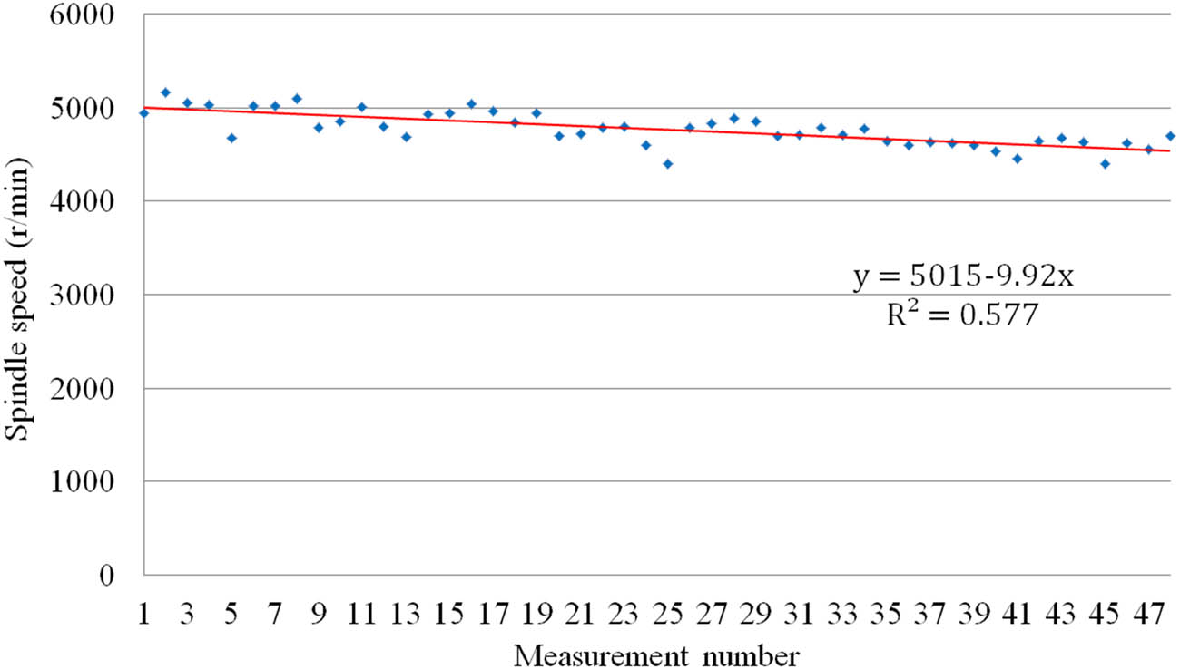
Data fitting of spindle speed.
The calculated spindle speed data are fitted by the least square method to obtain the red straight line in Figure 4. The fitting equation is
After the spindle speed is determined, the elevating speed of the traveler can be calculated by equation (6). As shown in Figure 5, the blue curve is the calculation result of the elevating traveler speed
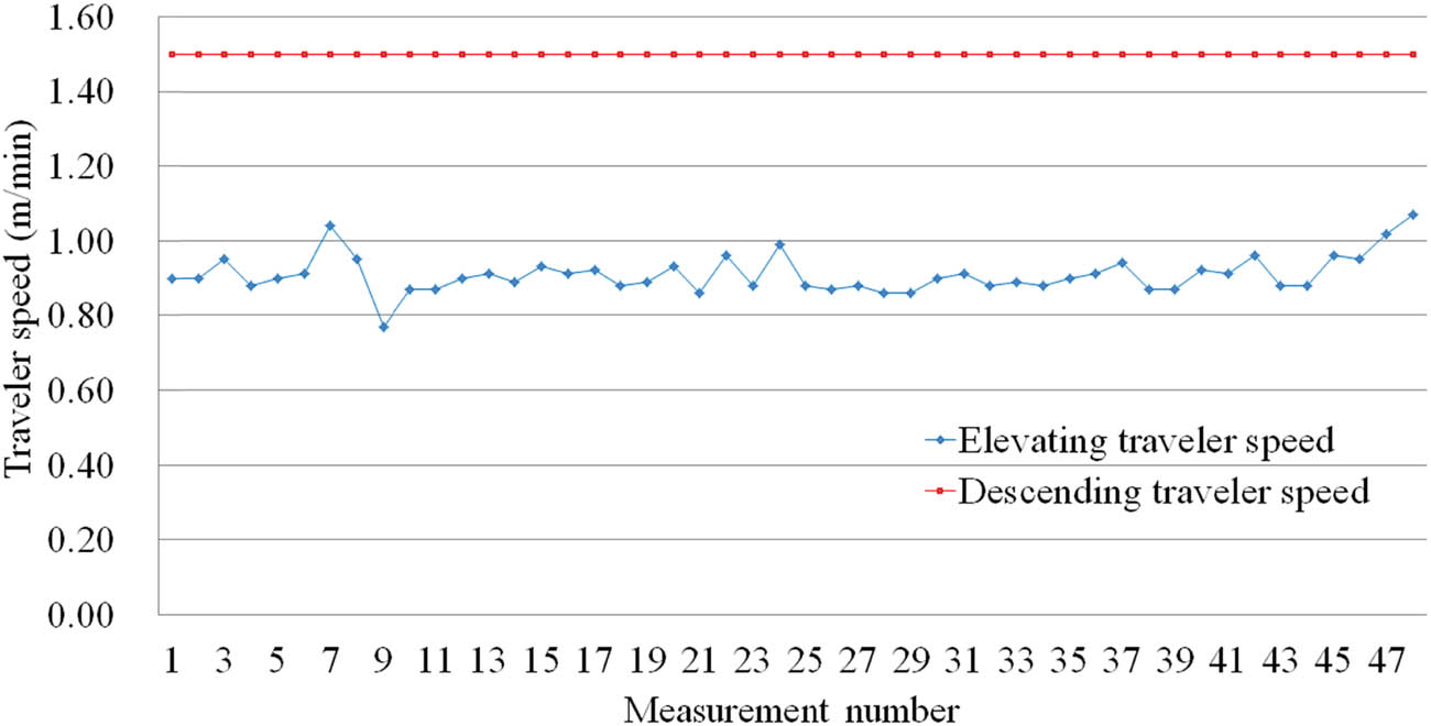
Calculation result of elevating traveler speed.
Take the average of the elevating traveler speed in Figure 5, that is,
Twisting process parameters of D450 E-glass yarn
| Process parameters | Values |
|---|---|
| Yarn twist
|
31.8 T/m |
| Initial bobbin diameter
|
67.5 mm |
| Full bobbin diameter
|
113.7 mm |
| Bobbin yarn height
|
293.0 mm |
| Spindle speed
|
5,015–4,550 rpm |
| Elevating traveler speed
|
0.91 m/min |
| Descending traveler speed
|
1.50 m/min |
5 Verification of twisting process parameters
According to the process parameters calculated in Table 2, a twisting experiment is carried out on a Verdol twisting machine. The accuracy of the calculation can be verified by monitoring the real-time rotation speed of the roving cake during the twisting process, measuring the actual loop pitch of the bobbin yarn after the twisting is completed, and comparing the actual value with the predicted value.
Whether the Verdol twisting machine or Volkmann twisting machine, the control unit of the equipment can display the real-time rotating speed of the roving cake during the twisting process, and the theoretical rotating speed of the roving cake can be calculated by equation (4). In the twisting experiment, the initial diameter of the roving cake is 329 mm, which gradually decreases to 306 mm during the twisting process. Meanwhile, the twist and spindle speed data in Table 2 are substituted into equation (4), and the predicted value of the roving cake speed is calculated. By monitoring and recording the real-time rotation speed of the roving cake, it is compared with the predicted rotation speed of the roving cake, as shown in Figure 6.

Comparison between predicted and actual roving cake speed.
By comparing the predicted value and the actual value of the roving cake speed in Figure 6, it is found that the theoretical rotation speed of the roving cake is very close to the actual monitoring result, and the prediction error is less than 0.4%, which indicates that the analysis and derivation of the twisting principle of E-glass yarn in Section 2 is accurate and reliable.
When the twisting experiment is finished, the elevating and descending loop pitch of the experimental bobbin yarn are measured by the same method as in Section 3. The data of twist, diameter, spindle speed, and traveler speed in Table 2 are substituted into equation (6) to calculate the theoretical loop pitch. The predicted value and the actual value of the elevating and descending loop pitch of bobbin yarn are compared, as shown in Figure 7.

Comparison between predicted and actual loop pitch.
By comparing the predicted value and the actual value of the elevating and descending loop pitch of bobbin yarn in Figure 7, it is found that the theoretical loop pitch of bobbin yarn is consistent with the actual measurement result, and the error between the predicted value and the actual value is less than 1.1%, which indicates that the deriving method of twisting process parameters has a precise result.
6 Discussion
In Section 4, the linear fitting method is adopted to calculate spindle speed data, and the calculated spindle speed is also in good agreement with the experimental results. However, for different types of E-glass yarn, there may be a multi-section spindle speed scheme. Verdol and Volkmann twisting machine can set the spindle speed of up to ten sections, and the spindle speed in each section can be controlled according to the yarn twisting length, but the spindle speed in each section can only change linearly or remain constant. By setting the twisting spindle speed in sections, various influencing factors such as productivity and yarn tension can be taken into account together [17], and more accurate control of the twisting process can be realized.
Besides, when setting the twisting process parameters of E-glass yarn, in addition to the main parameters such as yarn twist, spindle speed, and the elevating and descending speed of the traveler, it is also necessary to input the diameter of the roving cake at the beginning and end. Because the diameter of the roving cake gradually decreases during twisting, the glass fiber twisting machine will gradually increase the rotation speed of the roving cake according to the input diameter of the roving cake to keep the yarn twist stable. Generally, the diameter of the roving cake is input according to the actual measured value. For example, the diameter of the roving cake input in Section 5 is 329–306 mm. However, due to various process methods such as covering and stacking layer by layer during the formation of the roving cake, the diameter of the roving cake may not change linearly when it is unwound, so the actual diameter of the roving cake may not be conducive to the stability of the yarn twist. According to the roving cake forming process, it may be better to adjust the input roving cake diameter value appropriately. When the roving cake is covered layer by layer, the minimum diameter of the roving cake can be appropriately increased. When the roving cake is stacked layer by layer, the maximum diameter of the roving cake can be appropriately reduced. The study on the diameter change law of the roving cake during unwinding will help to obtain more accurate values.
7 Conclusion
Based on the research on the twisting principle of large package E-glass yarn, this article reveals the relationship between the physical properties of bobbin yarn and the twisting process parameters and proposes a method to derive the spindle speed and the traveler speed by measuring the twist, loop pitch, and its corresponding diameter of bobbin yarn. By unwinding and measuring the D450 E-glass yarn with 31.8 T/m, it is found that the twisting spindle speed linearly decreases from 5,015 to 4,550 rpm, the elevating speed of the traveler is 0.91 m/min, and the descending speed of the traveler is 1.50 m/min. And then, the twisting experiment is carried out on a Verdol twisting machine. By monitoring the real-time rotating speed of the roving cake during the twisting process and measuring the actual loop pitch of bobbin yarn after twisting, it indicates that the prediction error is less than 1.1%. By this method, the twisting process parameters of large package E-glass yarn can be derived effectively, providing a reference for the twisting process design scheme of glass fiber strand manufacturers.
Acknowledgement
This work was supported by the Science and Technology Research Project of Education Department of Jiangxi Province (grant number GJJ2202801).
-
Conflict of interest: Authors state no conflict of interest.
References
[1] Wang X, Liao SQ, Hu LZ, Xiao P, Du PJ. A simple method for measuring the monofilament diameter of continuous filament yarn with high bending stiffness via synthetic laser imaging. Sci Eng Compos Mater. 2022;29(1):312–21.10.1515/secm-2022-0157Search in Google Scholar
[2] Bilisik K, Yolacan G. Single and multiple yarn pull-out on E-glass woven fabric structures. Text Res J. 2011;81(19):2043–55.10.1177/0040517511414976Search in Google Scholar
[3] Zheng TY, Yang KD, Wang X, Ning XC. Objective evaluation of sizing morphology of E-glass filament yarn. J Ind Text. 2022;51(4_Suppl):6563S–89S.10.1177/1528083720911218Search in Google Scholar
[4] Wang X, Zheng TY, Ning XC. Four testing and evaluation methods of the spreading effects on E-glass woven fabrics. Glass Technol-Eur J Glass Sci Technol Part A. 2021;62(6):198–204.Search in Google Scholar
[5] Wang JA, Zhou J, Wang L, Pan RR, Gao WD. Detection of residual yarn on spinning bobbins based on salient region detection. J Text Inst. 2019;110(6):838–46.10.1080/00405000.2018.1529850Search in Google Scholar
[6] Ayele M, Merga Y, Yilma A, Yilie D. Effect of yarn twist on tensile strength, abrasion and pilling resistance of plain-woven cotton fabric. Indian J Fibre Text Res. 2021;46(3):221–4.10.56042/ijftr.v46i3.31718Search in Google Scholar
[7] Celik O, Eren R. Experimental investigation of the relationship between the yarn tension and bobbin diameter in the warping process. Fibres Text East Europe. 2019;27(1):23–31.10.5604/01.3001.0012.7504Search in Google Scholar
[8] Tang HB, Xu BG, Tao XM, Feng J. Mathematical modeling and numerical simulation of yarn behavior in a modified ring spinning system. Appl Math Model. 2011;35(1):139–51.10.1016/j.apm.2010.05.013Search in Google Scholar
[9] Bobovich BB. Use of glass roving for the production of reinforced polymer composite materials by spraying. Glass Ceram. 2015;72(1–2):32–4.10.1007/s10717-015-9717-3Search in Google Scholar
[10] Koranne MV, Kanade PS, Bhagat RA, Bhavsar SD. Studies on package winding with modified traverse blades. Part I: Modification of existing system. Text Res J. 2015;85(20):2168–76.10.1177/0040517515592810Search in Google Scholar
[11] Przybyl K. Stable working conditions of the twisting-and-winding system of a ring spinning frame. Fibres Text East Europe. 2005;13(1):35–8.Search in Google Scholar
[12] Koroteeva LI, Khozina EN, Sekhin AP. Process of Creating Bobbins from Glass and Basalt Threads at High Winding Rates. Fibre Chem. 2019;50(6):584–7.10.1007/s10692-019-10035-2Search in Google Scholar
[13] Belforte G, Ivanov A, Maffiodo D, Testore F. Winding core spun elastic yarns on cone bobbins to be dyed. J Text Inst. 2009;100(5):412–9.10.1080/00405000701863319Search in Google Scholar
[14] Shim WS, Lee H, Lee DW. The interaction of moving yarns with stationary surfaces. Fibers Polym. 2013;14(1):164–71.10.1007/s12221-013-0164-xSearch in Google Scholar
[15] Hossain M, Telke C, Abdkader A, Sparing M, Espenhahn T, Huhne R, et al. Mathematical modelling of dynamic yarn path considering the balloon control ring and yarn elasticity in the ring spinning process based on the superconducting bearing twisting element. Fibres Text East Europe. 2018;26(5):32–40.10.5604/01.3001.0012.2528Search in Google Scholar
[16] Kim JS, Yoon HE, Kim DW. Design of traverse cam for yarn winding on twisting machine. Fibers Polym. 2005;6(2):151–5.10.1007/BF02875607Search in Google Scholar
[17] Hossain M, Telke C, Abdkader A, Cherif C, Beitelschmidt M. Mathematical modeling of the dynamic yarn path depending on spindle speed in a ring spinning process. Text Res J. 2016;86(11):1180–90.10.1177/0040517515606355Search in Google Scholar
© 2023 the author(s), published by De Gruyter
This work is licensed under the Creative Commons Attribution 4.0 International License.
Articles in the same Issue
- Regular Articles
- Effects of cellulose nanofibers on flexural behavior of carbon-fiber-reinforced polymer composites with delamination
- Damage mechanisms of bismaleimide matrix composites under transverse loading via quasi-static indentation
- Experimental study on hydraulic fracture behavior of concrete with wedge-splitting testing
- The assessment of color adjustment potentials for monoshade universal composites
- Metakaolin-based geopolymers filled with volcanic fly ashes: FT-IR, thermal characterization, and antibacterial property
- The effect of temperature on the tensile properties and failure mechanisms of two-dimensional braided composites
- The influence of preparation of nano-ZrO2/α-Al2O3 gradient coating on the corrosion resistance of 316L stainless steel substrate
- A numerical study on the spatial orientation of aligning fibrous particles in composites considering the wall effect
- A simulative study on the effect of friction coefficient and angle on failure behaviors of GLARE subjected to low-velocity impact
- Impact resistance capacity and degradation law of epoxy-coated steel strand under the impact load
- Analytical solutions of coupled functionally graded conical shells of revolution
- The influence of water vapor on the structural response of asphalt pavement
- A non-invasive method of glucose monitoring using FR4 material based microwave antenna sensor
- Chloride ion transport and service life prediction of aeolian sand concrete under dry–wet cycles
- Micro-damage analysis and numerical simulation of composite solid propellant based on in situ tensile test
- Experimental study on the influence of high-frequency vibratory mixing on concrete performance
- Effects of microstructure characteristics on the transverse moisture diffusivity of unidirectional composite
- Gradient-distributed ZTAp-VCp/Fe45 as new anti-wear composite material and its bonding properties during composite casting
- Experimental evaluation of velocity sensitivity for conglomerate reservoir rock in Karamay oil field
- Mechanical and tribological properties of C/C–SiC ceramic composites with different preforms
- Mechanical property improvement of oil palm empty fruit bunch composites by hybridization using ramie fibers on epoxy–CNT matrices
- Research and analysis on low-velocity impact of composite materials
- Optimizing curing agent ratios for high-performance thermosetting phthalonitrile-based glass fibers
- Method for deriving twisting process parameters of large package E-glass yarn by measuring physical properties of bobbin yarn
- A probability characteristic of crack intersecting with embedded microcapsules in capsule-based self-healing materials
- An investigation into the effect of cross-ply on energy storage and vibration characteristics of carbon fiber lattice sandwich structure bionic prosthetic foot
- Preparation and application of corona noise-suppressing anti-shedding materials for UHV transmission lines
- XRD analysis determined crystal cage occupying number n of carbon anion substituted mayenite-type cage compound C12A7: nC
- Optimizing bending strength of laminated bamboo using confined bamboo with softwoods
- Hydrogels loaded with atenolol drug metal–organic framework showing biological activity
- Creep analysis of the flax fiber-reinforced polymer composites based on the time–temperature superposition principle
- A novel 3D woven carbon fiber composite with super interlayer performance hybridized by CNT tape and copper wire simultaneously
- Effect of aggregate characteristics on properties of cemented sand and gravel
- An integrated structure of air spring for ships and its strength characteristics
- Modeling and dynamic analysis of functionally graded porous spherical shell based on Chebyshev–Ritz approach
- Failure analysis of sandwich beams under three-point bending based on theoretical and numerical models
- Study and prediction analysis on road performance of basalt fiber permeable concrete
- Prediction of the rubberized concrete behavior: A comparison of gene expression programming and response surface method
- Study on properties of recycled mixed polyester/nylon/spandex modified by hydrogenated petroleum resin
- Effect of particle size distribution on microstructure and chloride permeability of blended cement with supplementary cementitious materials
- In situ ligand synthesis affording a new Co(ii) MOF for photocatalytic application
- Fracture research of adhesive-bonded joints for GFRP laminates under mixed-mode loading condition
- Influence of temperature and humidity coupling on rutting deformation of asphalt pavement
- Review Articles
- Sustainable concrete with partial substitution of paper pulp ash: A review
- Durability and microstructure study on concrete made with sewage sludge ash: A review (Part Ⅱ)
- Mechanical performance of concrete made with sewage sludge ash: A review (Part Ⅰ)
- Durability and microstructure analysis of concrete made with volcanic ash: A review (Part II)
- Communication
- Calculation of specific surface area for tight rock characterization through high-pressure mercury intrusion
- Special Issue: MDA 2022
- Vibration response of functionally graded material sandwich plates with elliptical cutouts and geometric imperfections under the mixed boundary conditions
- Analysis of material removal process when scratching unidirectional fibers reinforced polyester composites
- Tailoring the optical and UV reflectivity of CFRP-epoxy composites: Approaches and selected results
- Fiber orientation in continuous fiber-reinforced thermoplastics/metal hybrid joining via multi-pin arrays
- Development of Mg-based metal matrix biomedical composites for acicular cruciate ligament fixation by reinforcing with rare earth oxide and hydroxyapatite – A mechanical, corrosion, and microstructural perspective
- Special Issue: CACMSE
- Preparation and application of foamed ceramic panels in interior design