Effect of different welding procedures on microstructure and mechanical property of TA15 titanium alloy joint
-
Bingzhou Hu
 und
Kang Li
und
Kang Li

Abstract
TA15 titanium alloy is welded by electron beam welding (EBW) and pulsed Nd:YAG laser beam welding (P-LBW), respectively. Results show that the fusion zone (FZ) is mainly composed of acicular α′ martensite, while the acicular α′ martensite in the FZ of EBW joint is coarser. The quantity of martensite in the FZ of EBW joint is larger and the distribution of martensite is denser. The microstructure of heat-affected zone (HAZ) of the two joints is similar. The HAZ near FZ consists of primary α phase and acicular α′ martensite, and the HAZ near base metal (BM) consists of primary α phase, secondary α phase, and β phase. The hardness in the FZ of EBW joint is slightly higher than that of the P-LBW joint. The tensile strength of both joints is close to that of the BM, but their elongations are decreased to a certain extent. The tensile performance of the EBW joint is slightly better than that of the P-LBW joint. Both joints fail in the BM during stretching. There are many dimples on the fracture surfaces, and the two joints obviously present the characteristics of ductile fracture.
1 Introduction
Titanium alloys have the advantages of low density, high specific strength, good corrosion resistance, and high temperature performance, and they are widely used in many fields such as aerospace, marine engineering, and petrochemical industry [1,2,3]. The TA15 alloy is a near α-type titanium alloy. It has higher strength of α-type titanium alloy at high temperature, and its plasticity is close to that of α + β type titanium alloy. In aerospace field, TA15 alloy could be used to fabricate important structural components at high operating temperature and complex stress states, such as aircraft frame, panel, and engine blade [4,5].
Welded structures of many titanium alloy components were often employed in aerospace industry [6]. Due to the high chemical activity of titanium, the welding of titanium alloys is relatively difficult. At present, some methods are used to weld titanium alloys, such as tungsten inert gas arc welding (TIG), electron beam welding (EBW), and laser beam welding (LBW). Compared with the conventional fusion welding, high-energy beam welding such as EBW and LBW had the advantages of high energy density, large depth-to-width ratio, and small welding deformation [7,8,9], which was suitable for the welding of titanium alloys. In addition, the vacuum environment could protect the titanium alloys from oxidation and gas contamination during EBW process [10]. Many researchers had studied the high-energy beam welding technology and weldability of titanium alloys. The EBW of Ti–6Al–4V alloy was carried out, and results showed that the microstructure in different zones of welded joint was different due to the effect of weld thermal cycle [11]. Rae et al. [12] studied the microstructural evolution and residual stress of Ti–6Al–4V alloy EBW joint. In different zones of joint, its microstructure was different, which resulted in non-uniform distribution of microhardness in weld zone. The hardness in the fusion zone (FZ) was the maximum. Deng et al. [8] investigated the effect of microstructure inhomogeneity on mechanical property of different zones in TA15 alloy EBW joint. In addition, the effect of welding parameters on the microstructure of TA15 alloy LBW joint was studied [13]. The welding heat input had a great influence on the martensite morphology in weldment. When the heat input was low, the martensite mostly presented a parallel state. When the heat input was high, the martensite was scattered without obvious directionality. LBW can be divided into the pulsed LBW and the continuous LBW. In the pulsed Nd:YAG LBW (P-LBW) process, the workpiece was heated periodically by the intermittent pulsed laser beam, and the weld zone was melted and the molten pool solidified consecutively [14]. The heat input can be accurately controlled during the P-LBW process. Compared with that of the continuous LBW process, the weld porosity could be decreased in titanium alloy joint by P-LBW process due to its shorter time for the solidification of molten pool [15,16]. Akman et al. [17] concluded that the penetration depth and weld morphology could be controlled by the P-LBW parameters. The microhardness in weld zone was related to the peak laser power and pulse duration.
At present, a single EBW process or LBW process is often employed to investigate the welding of titanium alloys, while there are few reports on the comparative study of EBW and P-LBW for titanium alloys. Due to the different fundamental principle and process between EBW and LBW, the microstructure and property of welded joints obtained by the two welding processes are different. In order to understand the effect of EBW and LBW on the microstructure and property of titanium alloy joints, in the present work, the TA15 alloy is welded by using EBW and P-LBW, respectively. The appearance of weld, microstructure, and mechanical property of welded joints obtained by the two welding processes are systematically studied, based on which some suggestions can be provided for the selection of welding procedure during industrial application.
2 Material and procedure
The base metal (BM) is TA15 titanium alloy with a thickness of 3 mm, and its nominal chemical composition is as follows (wt%): Ti–6.5 Al–2 Zr–1 Mo–1 V. The microstructure of BM is shown in Figure 1, and it consists of equiaxed primary α phase and β phase. The BM is machined to welding sample with the dimensions of 100 mm × 50 mm × 3 mm by wire cut electrical discharge machining (WEDM). Before welding, mechanical and chemical cleaning are carried out on the welding sample, respectively, so as to remove the oxide film and contamination on the sample surface. The butt joint is used, and the samples are welded along the longitudinal direction by EBW and P-LBW, respectively. The schematic diagram of EBW and P-LBW process is shown in Figure 2.

Microstructure of TA15 titanium alloy.

Schematic diagram of welding process: (a) EBW and (b) P-LBW.
The EBW equipment is TETA-6E800M2 type EBW machine, as shown in Figure 3(a). During EBW, the pressure of vacuum chamber is 5 × 10⁻⁴ Pa, acceleration voltage is 60 kV, and working distance is 300 mm. In addition, in order to improve the weld formation, refine grains in weldment, and decrease the susceptibility to welding defects, a circular electron beam scanning is employed during EBW, and the scanning frequency is 500 Hz and scanning amplitude is 1%. IPG4000 type Nd:YAG laser is used for the P-LBW of sample. The P-LBW equipment is shown in Figure 3(b). During P-LBW process, argon gas is used as the shielding gas with a gas flow rate of 20 L·min−1. Some attempt welding processes are carried out by EBW and P-LBW, respectively. Based on the observation of weld formation and the measurement of joint mechanical property, the welding parameters are determined under the experimental condition. The EBW parameters are shown in Table 1, and the P-LBW parameters are shown in Table 2. The heat input is calculated by the following equation (1) [18].
where Q is the heat input; η is the thermal efficiency, which is taken as 0.95 for EBW, and 0.9 for P-LBW; v is the welding speed; P is the beam power, and P = UI for EBW, U is the acceleration voltage and I is the electron beam current.
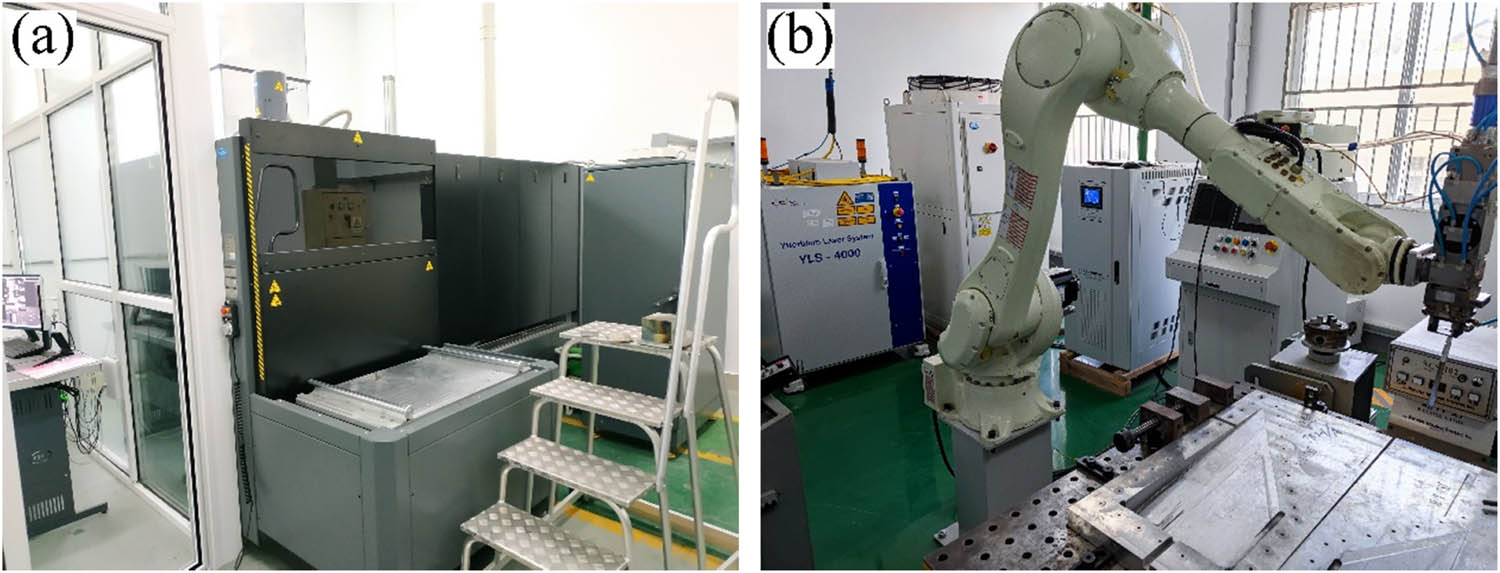
Welding equipment: (a) EBW machine and (b) P-LBW machine.
EBW parameters of TA15 titanium alloy
| Focusing current (mA) | Electron beam current (mA) | Welding speed (mm·min−1) | Heat input (J·mm−1) |
|---|---|---|---|
| 580 | 22 | 700 | 107.5 |
P-LBW parameters of TA15 titanium alloy
| Pulse duration (s) | Pulse frequency (Hz) | Average laser power (W) | Welding speed (mm·min−1) | Defocusing amount (mm) | Heat input (J·mm−1) |
|---|---|---|---|---|---|
| 0.01 | 100 | 2,350 | 1,500 | 0 | 84.6 |
After welding, the microstructure and mechanical property of the welded joint are analyzed. The metallographic sample is cut from the welded joint which is perpendicular to the weld center by WEDM. It is ground and polished, and then etched with Kroll reagent (volume fraction: 2% HF + 6% HNO3 + 92% distilled water). The microstructure of weld zone is observed by using MM6 optical microscope (OM). The phase constituent of FZ is identified by using SmartLab 9 kW type X-ray diffractometer (XRD). The diffraction range is taken from 20° to 80° with the scanning rate of 2°·min−1. The JEM-2001F type transmission electron microscope (TEM) is used to investigate the substructure of the weldment. Microhardness in weld zone is measured by using HXS-1000AY hardness tester with a load of 200 g and duration time of 15 s, and the spacing between two test points is about 0.1 mm. The tensile tests are carried out on the two joints by using CMT-5105 electronic universal material testing machine with a loading rate of 1 mm·min−1. Each joint is measured three times (namely three tensile samples of each joint, respectively) and the average is taken as the result of tensile tests. The morphology of tensile fracture is observed by using JSM-6360LV type scanning electron microscope (SEM), and the fracture characteristic of welded joint is analyzed.
3 Results and discussion
3.1 Appearance of weld
The macrographs of EBW and P-LBW joints are shown in Figure 4. It can be seen that the top and the root surfaces of both weldments are well formed. The appearance of weld is uniform, continuous, and smooth, and no welding defects such as oxidation and micro-crack are generated in the two joints.

Appearance of weld: (a) top surface of EBW joint, (b) root surface of EBW joint, (c) top surface of P-LBW joint, and (d) root surface of P-LBW joint.
The cross section profiles of EBW and P-LBW joints are shown in Figure 5. Both joints are fully penetrated and no welding defects such as gas pores are generated. Due to the relatively high heat input in the EBW process, the weld width of EBW joint is larger than that of the P-LBW joint. The weld morphology of EBW joint presents V-shape, and it is wide at the top, while narrow at the bottom, as shown in Figure 5(a). In the EBW process, the liquid metal flowed from bottom to top of the keyhole, and simultaneously the edge of keyhole was expanded due to the combined effect of surface tension of the molten pool, metal vapor counterforce, and other forces [19]. The heat transfer will be enhanced in the molten pool by such circular flow, which results in the increase in the width from bottom to top of the molten pool. The weld morphology of P-LBW joint approximately presents the X-shape, as shown in Figure 5(b), and it is wide at the top and the bottom, while narrow at the middle. It could be understood by the mode of open keyhole [20]. In the P-LBW process, the laser beam is reflected many times within the keyhole, which results in the temperature difference between the top and the bottom of the molten pool. The surface tension will be changed between the top and the bottom of the molten pool, and a recoil pressure is generated along the keyhole. As a result, the width of the molten pool at the bottom is increased. Because the reflected laser beam continuously escaped from the top and the bottom of the molten pool, they were enlarged to a certain extent [21].

Cross section profile of the welded joint: (a) EBW joint and (b) P-LBW joint.
3.2 Microstructure of welded joint
The microstructures of EBW and P-LBW joints of TA15 alloy are shown in Figures 6 and 7, respectively. Usually, the welded joint can be divided into three parts, namely the FZ, heat-affected zone (HAZ), and BM.

Microstructure of EBW joint: (a) the upper part of FZ, (b) the middle part of FZ, (c) magnification of area c in (b), (d) HAZ, and (e) magnification of area e in (d).

Microstructure of P-LBW joint: (a) the upper part of FZ, (b) the middle part of FZ, (c) magnification of area c in (b), (d) HAZ, and (e) magnification of area e in (d).
In FZ, the coarse columnar crystals grow perpendicular to the fusion line (FL). During the cooling process of the molten pool, columnar crystals are formed by the pattern of epitaxial nucleation and growth. The grains preferentially grow up, and their growth directions are along the maximum temperature gradient. The columnar crystals at the upper part of FZ grow from the FL to weld center, as shown in Figures 6(a) and 7(a). The columnar crystals in the middle part of FZ grow perpendicular to the weld center, as shown in Figures 6(b) and 7(b). The columnar crystals in the FZ of EBW joint are coarser than those of the P-LBW joint. Because the heat input is relatively high during EBW, it will promote the grain growth to a certain extent. As shown in Figures 6(c) and 7(c), there are a large amount of acicular α′ martensite in the columnar crystals. In the EBW and P-LBW processes, the temperature in FZ is the maximum, and it is much higher than the melting point of TA15 alloy, which results in the partial melting of BM. In the subsequent cooling process, the liquid metal is first solidified to form the β phase. With the rapid decrease in temperature in FZ, there was no enough time for the β phase to transform into the α phase, and it only transformed into the α′ phase through non-diffusion transformation [22]. SEM images of acicular α′ martensite in the FZ are shown in Figure 8. Compared with that of the P-LBW joint, the martensite in the FZ of EBW joint is coarser, which is related to the higher heat input in EBW process. The arrangement of martensite is interlaced in the FZ of both joints, and it presents the typical basket-weave structure.

SEM image of α′ martensite in FZ: (a) EBW joint and (b) P-LBW joint.
During welding, the peak temperature is different due to the different distances away from the weld center, and it has corresponding microstructure in different zones of joint under the effect of weld thermal cycle. The HAZ of joint can be divided into the coarse grain HAZ (CG-HAZ) near FZ and the fine grain HAZ (FG-HAZ) near BM, as shown in Figures 6(d) and 7(d), respectively. For both joints, microstructure in the HAZ is similar, but the grain size is slightly different. During welding, the CG-HAZ is near heat source, and the peak temperature is higher. A large amount of primary α phase transform into the β phase, and only a small amount of primary α phase is retained. In the subsequent cooling process, due to the rapid cooling rate, there is no enough time for the β phase to transform into the α phase by the mode of atomic diffusion. At this time, atoms in the β phase regularly migrated in a short-distance, and the β phase transformed into the acicular α′ martensite by the shear mode [22]. Consequently, the CG-HAZ of both joints consists of primary α phase and acicular α′ martensite, as shown in Figures 6(e) and 7(e), respectively. Compared with those in the P-LBW joint, the size of α′ martensite and α grains in the CG-HAZ of EBW joint are relatively large. Because the FG-HAZ is far away from the heat source during welding, the peak temperature is low. A small amount of primary α phase in the BM transforms into the β phase, and a large amount of primary α phase is retained. In the cooling process, the fine secondary α phase is precipitated from the β phase. As a result, the FG-HAZ of both joints consists of primary α phase, secondary α phase, and β phase, as shown in Figures 6(e) and 7(e).
In order to identify the phase constituent of weldment, XRD analyses are carried out on the FZ of both joints, as shown in Figure 9. By comparison with the standard powder diffraction file card of α′ phase, the results show that there is mainly α′ martensite with the crystal face indices of (101̄0), (0002), (101̄1), (101̄2), (112̄0), (101̄3), (112̄2), and (202̄1) in the FZ of both joints. The diffraction peak intensity of α′ phase in the FZ of EBW joint is obviously higher than that of the P-LBW joint, which indicates that the quantity of α′ martensite in the FZ of EBW joint is more than that of the P-LBW joint. Due to the low content of β phase stabilizer in TA15 alloy, the quantity of residual β phase in the FZ of both joints is low after phase transition. The diffraction peak intensity of β phase is very weak, thus it is difficult to be identified by the XRD analysis.

X-ray diffraction pattern of weldment: (a) EBW joint and (b) P-LBW joint.
TEM images of the FZ of both joints are shown in Figure 10. The FZ of both joints consists of a large amount of parallel aligned lath-like α′ martensite and a small amount of remaining β phase between the α′ martensites, as shown in Figure 10(a) and (d). There are some smaller lath-like α′ martensites around the parallel aligned α′ martensites, which presents the interlaced distribution over each other, as shown in Figure 10(b) and (e). The α′ martensite in FZ nucleates and grows at the columnar crystal boundary and within grains. During welding, when the liquid metal solidifies, one or several parallel primary α′ martensites first form, and it expands to the whole grain boundary in a long distance. Subsequently, a series of relatively small secondary α′ martensites form, and a typical basket-weave martensite structure is generated in the FZ. Gao et al. [23] stated that the stacking faults near the boundary of lath-like martensite could induce the generation of secondary martensite. Compared with that in the P-LBW joint, the martensite in the FZ of EBW joint is coarser and its distribution is denser. During EBW process, the higher heat input will result in the higher peak temperature and the larger temperature gradient, thus the quantity of the transformed martensite is increased. The growth of martensite is a process of martensite thickening, which leads to the increase in martensite size. In the present work, the heat input in the EBW is higher than that in the P-LBW, the quantity of transformed martensite in the FZ of EBW joint is more after the rapid cooling of the molten pool. Consequently, the martensite in the FZ of EBW joint is coarser and is distributed densely.

TEM images of FZ: (a) parallel aligned lath-like martensite in the FZ of EBW joint, (b) interlaced lath-like martensite in the FZ of EBW joint, (c) dislocations within lath-like martensite in the FZ of EBW joint, (d) parallel aligned lath-like martensite in the FZ of P-LBW joint, (e) interlaced lath-like martensite in the FZ of P-LBW joint, and (f) dislocations within lath-like martensite in the FZ of P-LBW joint.
There are high density dislocations within the lath-like martensite in the FZ of EBW joint, as shown in Figure 10(c). The dislocations within the lath-like martensite in the FZ of P-LBW joint are relatively few, as shown in Figure 10(f). The formation of high-density dislocations is due to the addition of circular electron beam scanning during EBW process. The high-density dislocations in the FZ of EBW joint were easy to move under the condition of high temperature and pressure [24]. During EBW process, the periodic oscillation of electron beam will produce a dynamic pressure at the solidification front of molten pool, and a stress (σ) is generated. The elastic deformation can be induced in the solid phase. When the stress value (σ) exceeds the yield strength (σ s) of the material, the plastic deformation will be generated and accompanies the formation of dislocations. The dislocation density (ρ) could be calculated by the following equation (2) [25].
where E is the elastic modulus and b is the Burger’s vector. As the yield strength of solid phase adjacent to molten pool is close to zero, the stress produced by lower dynamic pressure can result in a lot of new dislocations. At high temperature, the dislocations would redistribute in the solid phase after the crystallization of the molten pool, and the dislocations with positive and negative directions would disappear and form subgrain boundary [24]. The internal stress in the weldment at high temperature and the dynamic pressure on solidification front by electron beam scanning are advantageous to the formation of subgrain boundary. The dislocation density and its distribution in weldment mainly depend on the combined effect of dynamic pressure on the molten pool by electron beam scanning and the stability of the solidification front. When coarse columnar crystals are formed in the FZ, the stability of the molten pool solidification is decreased by electron beam scanning during welding. A large number of dislocations produced at high temperature will be retained in the FZ. When fine equiaxed grains are formed in the FZ, the dynamic pressure on solidification front by electron beam scanning can match the stability of solidification front of the molten pool. At this time, the dislocations generated at high temperature with positive and negative directions will disappear to form subgrain boundary, thus the quantity of dislocations in the FZ is less.
3.3 Microhardness distribution
The microhardness distribution curves of the two joints are shown in Figure 11. The hardness distribution of the two joints is basically the same. The hardness curve on both sides of the weldment is roughly symmetrical to the weld center, and the hardness in different zones of the joint is different. The hardness in both the FZ and the HAZ is higher than that in the BM, and the hardness in the FZ is the maximum. Because the cooling rate in the FZ is rapid during welding, the β phase transforms into the α′ martensite. There are high density dislocations in the α′ martensite, which results in the increase in resistance to dislocation motion, thus the hardness in the FZ is increased. The hardness of existing phases in titanium alloy joint was ranked as follows [26]: α′ phase > α phase > β phase. During high-energy beam welding, the rapid cooling rate will lead to a large amount of α′ martensite in the FZ. Compared with that in the FZ, the peak temperature in the HAZ is lower, and its cooling rate is relatively low. The quantity of α′ martensite is less in the HAZ, thus the hardness in the HAZ is lower than that in the FZ. From FG-HAZ (HAZ near BM) to CG-HAZ (HAZ near FZ), the hardness is gradually increased, which is related to the quantity of α′ martensite in these two zones.

Microhardness distribution of weld zone: (a) EBW joint and (b) P-LBW joint.
As shown in Figure 11, the width of HAZ in the P-LBW joint is narrower, and the hardness gradient in the HAZ is larger. It means that the mechanical property in the HAZ of P-LBW joint is non-uniform. The average hardness in the FZ of EBW joint is 380 HV, and that in the P-LBW joint is 365 HV. The hardness in the FZ of EBW joint is slightly higher than that in the P-LBW joint. The hardness in the FZ depends on the grain size and the quantity of α′ martensite transformed from the β phase. During EBW process, the relatively high heat input leads to the coarser β grains in the FZ, and the hardness in the FZ is accordingly varied. The heat input is different in different welding processes, and the decrease in hardness caused by grain growth was less than that caused by the increase in the transformed martensite [27]. The more the quantity of α′ martensite in the FZ is, the higher the hardness is. As described above, compared with that of the P-LBW joint, the quantity of martensite in the FZ of EBW joint is larger and its distribution is denser. As a result, the hardness in the FZ of EBW joint is relatively high.
3.4 Tensile property and fracture analysis
Results of tensile tests of TA15 BM and the two joints are listed in Table 3. The tensile stress–strain curves of the BM and welded joints are shown in Figure 12. The TA15 BM has higher tensile strength and plasticity, which are related to the equiaxed α phase and β phase in the BM [28]. From Table 3, it can be seen the tensile strength of the two joints is close to that of the BM. The joint efficiency of EBW joint is 97.8%, and the joint efficiency of P-LBW joint is 94.8%. Compared with that of the BM, the elongation of both the joints is decreased to a certain extent. The tensile strength of EBW joint is slightly higher than that of the P-LBW joint, which is related to the α′ martensite in the FZ. As mentioned above, compared with that of the P-LBW joint, the quantity of martensite in the FZ of EBW joint is larger and its distribution is denser, which is beneficial to improve the tensile strength of the EBW joint. In addition, there are high density dislocations within martensite in the FZ of EBW joint, which results in lattice distortion, and the resistance to plastic deformation is increased. Consequently, the joint strength is improved. Both joints fail in the BM during tensile process, which demonstrates that both joints have good mechanical performance.
Results of tensile tests of base metal and welded joints
| Sample | Tensile strength (MPa) | Elongation (%) | Fracture position |
|---|---|---|---|
| EBW joint | 1055.3 | 10.2 | BM |
| P-LBW joint | 1022.9 | 8.5 | BM |
| BM | 1079.1 | 13.4 | — |

Tensile stress–strain curves of base metal and welded joints.
The tensile fracture of the two joints is observed by using SEM, and the images of fracture morphology are shown in Figure 13. There are many dimples on the fracture surface, and the tearing ridge appears. Both the joints obviously present the characteristic of ductile fracture. As shown in Figure 13(a), the dimples on the fracture surface of EBW joint are relatively large and deep. However, the dimples on the fracture surface of P-LBW joint are relatively small and shallow, as shown in Figure 13(b). The dimples are generated by the coalescence of microvoids during the tensile process. Generally, when the plasticity and toughness of the welded joint is higher, the large and deep dimples will be produced on the fracture surface after stretching. From Table 3, the plasticity of the EBW joint is slightly higher than that of the P-LBW joint, which is consistent with the tensile fracture morphologies of the two joints.

SEM images of joint tensile fracture: (a) EBW joint and (b) P-LBW joint.
4 Comparison of EBW joint and P-LBW joint
In summary, when the appropriate welding parameters are determined, the titanium alloy joint with good mechanical property can be obtained by using EBW or P-LBW process. The two welding procedures are suitable for the welding of TA15 alloy. Compared with that of the P-LBW process, the heat input is relatively high during EBW process, and the quantity of transformed martensite in the EBW joint is larger and the distribution is denser. Consequently, the hardness and tensile strength of EBW joint are relatively high. During the practical application, EBW can be selected when the performance requirement of titanium alloy joint is higher. When the performance requirement of titanium alloy joint is not very high, P-LBW or EBW can be selected. In addition, EBW has good penetration ability, and it is suitable for the welding of thin or thick titanium alloy plates. P-LBW is more suitable for the welding of thin titanium alloy plate. Due to the limitation of vacuum chamber, the size of workpiece by EBW usually cannot be too large. When the size of welded structure is larger, P-LBW can be selected. On the whole, the titanium alloy joint has good mechanical property by using EBW or P-LBW process, and both joints can meet the performance requirement of engineering structure. The welding procedure can be reasonably selected in terms of the actual condition.
5 Conclusion
The weld morphology of EBW joint presents V-shape, and it is wide at the top and narrow at the bottom. However, the weld morphology of P-LBW joint approximately presents X-shape, and it is wide at the top and the bottom, while narrow at the middle. The appearance of weld is better, and no welding defects such as oxidation, crack, and gas pore are generated for both the joints.
Due to the relatively high heat input during EBW, the columnar crystals in the FZ of EBW joint are relatively coarse. There is a large amount of acicular α′ martensites in the FZ of both the joints. Compared with that of the P-LBW joint, the quantity of martensite in the FZ of EBW joint is larger and the distribution is denser, and there are high density dislocations within the martensite. The microstructures in the HAZ of the two joints are similar, but the grain sizes are slightly different. The HAZ near FZ is composed of primary α phase and acicular α′ martensite, and the HAZ near BM is composed of primary α phase, secondary α phase, and β phase.
The hardness in the FZ of EBW joint is slightly higher than that of the P-LBW joint. The tensile strength of both the joints is close to that of the BM. Compared with that of the BM, the elongation of both the joints is decreased to a certain extent. The tensile strength and elongation of EBW joint are slightly higher than those of the P-LBW joint. The two joints fail in the BM during stretching. There are many dimples on the fracture surface, and both the joints obviously present the characteristic of ductile fracture.
On the whole, the TA15 alloy joints by EBW or P-LBW process have good mechanical property, which can satisfy the performance requirement of an engineering structure. The welding procedure can be reasonably selected during practical application.
-
Funding information: A Project Funded by the Priority Academic Program Development of Jiangsu Higher Education Institutions (PAPD), which is gratefully acknowledged.
-
Author contributions: Bingzhou Hu: investigation, formal analysis, and writing-original draft; Shaogang Wang: methodology, supervision, and writing-review and editing; Kang Li: resources, experimental preparation, and formal analysis.
-
Conflict of interest: The authors declare that they have no known competing financial interests or personal relationships that could have appeared to influence the work reported in this article.
References
[1] Adamus, J., P. Lacki, and M. Motyka. EBW titanium sheets as material for drawn parts. Archives of Civil and Mechanical Engineering, Vol. 15, No. 1, 2015, pp. 42–47.10.1016/j.acme.2014.04.004Suche in Google Scholar
[2] Banerjee, D. and J. C. Williams. Perspectives on titanium science and technology. Acta Materialia, Vol. 61, No. 3, 2013, pp. 844–879.10.1016/j.actamat.2012.10.043Suche in Google Scholar
[3] Choi, W., J. Jourdan, A. Matveichev, A. Jardy, and J. P. Bellot. Kinetics of evaporation of alloying elements under vacuum: application to Ti alloys in electron beam melting. High Temperature Materials and Processes, Vol. 36, No. 8, 2017, pp. 815–823.10.1515/htmp-2015-0220Suche in Google Scholar
[4] Sun, Q. J. and G. C. Wang. Microstructure and superplasticity of TA15 alloy. Materials Science and Engineering A, Vol. 606, 2014, pp. 401–408.10.1016/j.msea.2014.03.117Suche in Google Scholar
[5] Wei, M. W., S. Y. Chen, J. Liang, and C. S. Liu. Effect of atomization pressure on the breakup of TA15 titanium alloy powder prepared by EIGA method for laser 3D printing. Vacuum, Vol. 143, 2017, pp. 185–194.10.1016/j.vacuum.2017.06.014Suche in Google Scholar
[6] Barreda, J. L., F. Santamarı́a, X. Azpiroz, A. M. Irisarri, and J. M. Varona. Electron beam welded high thickness Ti6Al4V plates using filler metal of similar and different composition to the base plate. Vacuum, Vol. 62, No. 2–3, 2001, pp. 143–150.10.1016/S0042-207X(00)00454-1Suche in Google Scholar
[7] Węglowski, M. S., S. Błacha, and A. Phillips. Electron beam welding-Techniques and trends-Review. Vacuum, Vol. 130, 2016, pp. 72–92.10.1016/j.vacuum.2016.05.004Suche in Google Scholar
[8] Deng, C. Y., C. Liu, B. M. Gong, C. Z. Zhang, C. Liu, and Y. Liu. Effect of microstructure inhomogeneity on mechanical properties of different zones in TA15 electron beam welded joints. Transactions of Nonferrous Metals Society of China, Vol. 30, No. 3, 2020, pp. 678–687.10.1016/S1003-6326(20)65245-1Suche in Google Scholar
[9] Rońda, J. and A. Siwek. Modelling of laser welding process in the phase of keyhole formation. Archives of Civil and Mechanical Engineering, Vol. 11, No. 3, 2011, pp. 739–752.10.1016/S1644-9665(12)60113-7Suche in Google Scholar
[10] Liu, H. Q., H. M. Wang, Z. Zhang, Y. J. Liu, Z. Y. Huang, Q. Y. Wang, et al. Tensile and fatigue behavior of electron beam welded TC17 titanium alloy joint. International Journal of Fatigue, Vol. 128, 2019, id. 105210.10.1016/j.ijfatigue.2019.105210Suche in Google Scholar
[11] Lu, W., Y. W. Shi, Y. P. Lei, and X. Y. Li. Effect of electron beam welding on the microstructures and mechanical properties of thick TC4-DT alloy. Materials and Design, Vol. 34, 2012, pp. 509–515.10.1016/j.matdes.2011.09.004Suche in Google Scholar
[12] Rae, W., Z. Lomas, M. Jackson, and S. Rahimi. Measurements of residual stress and microstructural evolution in electron beam welded Ti–6Al–4V using multiple techniques. Materials Characterization, Vol. 132, 2017, pp. 10–19.10.1016/j.matchar.2017.07.042Suche in Google Scholar
[13] Zhan, X. H., Q. Y. Peng, Y. H. Wei, and W. M. Ou. Experimental and simulation study on the microstructure of TA15 titanium alloy laser beam welded joints. Optics and Laser Technology, Vol. 94, 2017, pp. 279–289.10.1016/j.optlastec.2017.03.014Suche in Google Scholar
[14] Ghaini, F. M., M. J. Hamedi, M. J. Torkamany, and J. Sabbaghzadeh. Weld metal microstructural characteristics in pulsed Nd:YAG laser welding. Scripta Materialia, Vol. 56, No. 11, 2007, pp. 955–958.10.1016/j.scriptamat.2007.02.019Suche in Google Scholar
[15] Blackburn, J. E., C. M. Allen, P. A. Hilton, L. Li, M. I. Hoque, and A. H. Khan. Modulated Nd:YAG laser welding of Ti–6Al–4V. Science and Technology of Welding and Joining, Vol. 15, No. 5, 2010, pp. 433–439.10.1179/136217110X12731414739718Suche in Google Scholar
[16] Gao, X. L., L. J. Zhang, J. Liu, and J. X. Zhang. A comparative study of pulsed Nd:YAG laser welding and TIG welding of thin Ti6Al4V titanium alloy plate. Materials Science and Engineering A, Vol. 559, 2013, pp. 14–21.10.1016/j.msea.2012.06.016Suche in Google Scholar
[17] Akman, E., A. Demir, T. Canel, and T. Sınmazçelik. Laser welding of Ti6Al4V titanium alloys. Journal of Materials Processing Technology, Vol. 209, No. 8, 2009, pp. 3705–3713.10.1016/j.jmatprotec.2008.08.026Suche in Google Scholar
[18] Gao, F. Y., Q. Gao, P. Jiang, Z. Y. Liu, and Z. Q. Liao. Microstructure and properties of titanium alloy electron beam weldments based on the different heat input conditions of the same line energy. Vacuum, Vol. 146, 2017, pp. 136–141.10.1016/j.vacuum.2017.09.038Suche in Google Scholar
[19] Rai, R., P. Burgardt, J. O. Milewski, T. J. Lienert, and T. DebRoy. Heat transfer and fluid flow during electron beam welding of 21Cr-6Ni-9Mn steel and Ti–6Al–4V alloy. Journal of Physics D: Applied Physics, Vol. 42, No. 2, 2009, id. 025503.10.1088/0022-3727/42/2/025503Suche in Google Scholar
[20] Krasnoperov, M. Y., R. R. G. M. Pieters, and I. M. Richardson. Weld pool geometry during keyhole laser welding of thin steel sheets. Science and Technology of Welding and Joining, Vol. 9, No. 6, 2004, pp. 501–506.10.1179/136217104225021733Suche in Google Scholar
[21] Kumar, C., M. Das, C. P. Paul, and K. S. Bindra. Comparison of bead shape, microstructure and mechanical properties of fiber laser beam welding of 2 mm thick plates of Ti–6Al–4V alloy. Optics and Laser Technology, Vol. 105, 2018, pp. 306–321.10.1016/j.optlastec.2018.02.021Suche in Google Scholar
[22] Ahmed, T. and H. J. Rack. Phase transformations during cooling in α + β titanium alloys. Materials Science and Engineering A, Vol. 243, No. 1–2, 1998, pp. 206–211.10.1016/S0921-5093(97)00802-2Suche in Google Scholar
[23] Gao, F. Y., P. Y. Li, P. Jiang, and Z. Q. Liao. The effect of constraint conditions on microstructure and properties of titanium alloy electron beam welding. Materials Science and Engineering A, Vol. 721, 2018, pp. 117–124.10.1016/j.msea.2018.02.069Suche in Google Scholar
[24] Kou, S. Welding metallurgy, John Wiley and Sons, Inc, Hoboken, 2003.Suche in Google Scholar
[25] Han, Z., H. Zhao, X. F. Chen, and H. C. Lin. Corrosion behavior of Ti–6Al–4V alloy welded by scanning electron beam. Materials Science and Engineering A, Vol. 277, No. 1–2, 2000, pp. 38–45.10.1016/S0921-5093(99)00561-4Suche in Google Scholar
[26] Zeng, L. and T. R. Bieler. Effects of working, heat treatment, and aging on microstructural evolution and crystallographic texture of α, α′, α″ and β phases in Ti–6Al–4V wire. Materials Science and Engineering A, Vol. 392, No. 1–2, 2005, pp. 403–414.10.1016/j.msea.2004.09.072Suche in Google Scholar
[27] Junaid, M., F. N. Khan, N. Bakhsh, M. N. Baig, and K. Rahman. Study of microstructure, mechanical properties and residual stresses in full penetration electron beam welded Ti-5Al-2.5Sn alloy sheet. Materials and Design, Vol. 139, 2018, pp. 198–211.10.1016/j.matdes.2017.11.009Suche in Google Scholar
[28] Chamanfar, A., T. Pasang, A. Ventura, and W. Z. Misiolek. Mechanical properties and microstructure of laser welded Ti–6Al–2Sn-4Zr-2Mo (Ti6242) titanium alloy. Materials Science and Engineering A, Vol. 663, 2016, pp. 213–224.10.1016/j.msea.2016.02.068Suche in Google Scholar
© 2022 Bingzhou Hu et al., published by De Gruyter
This work is licensed under the Creative Commons Attribution 4.0 International License.
Artikel in diesem Heft
- Research Articles
- Numerical and experimental research on solidification of T2 copper alloy during the twin-roll casting
- Discrete probability model-based method for recognition of multicomponent combustible gas explosion hazard sources
- Dephosphorization kinetics of high-P-containing reduced iron produced from oolitic hematite ore
- In-phase thermomechanical fatigue studies on P92 steel with different hold time
- Effect of the weld parameter strategy on mechanical properties of double-sided laser-welded 2195 Al–Li alloy joints with filler wire
- The precipitation behavior of second phase in high titanium microalloyed steels and its effect on microstructure and properties of steel
- Development of a huge hybrid 3D-printer based on fused deposition modeling (FDM) incorporated with computer numerical control (CNC) machining for industrial applications
- Effect of different welding procedures on microstructure and mechanical property of TA15 titanium alloy joint
- Single-source-precursor synthesis and characterization of SiAlC(O) ceramics from a hyperbranched polyaluminocarbosilane
- Carbothermal reduction of red mud for iron extraction and sodium removal
- Reduction swelling mechanism of hematite fluxed briquettes
- Effect of in situ observation of cooling rates on acicular ferrite nucleation
- Corrosion behavior of WC–Co coating by plasma transferred arc on EH40 steel in low-temperature
- Study on the thermodynamic stability and evolution of inclusions in Al–Ti deoxidized steel
- Application on oxidation behavior of metallic copper in fire investigation
- Microstructural study of concrete performance after exposure to elevated temperatures via considering C–S–H nanostructure changes
- Prediction model of interfacial heat transfer coefficient changing with time and ingot diameter
- Design, fabrication, and testing of CVI-SiC/SiC turbine blisk under different load spectrums at elevated temperature
- Promoting of metallurgical bonding by ultrasonic insert process in steel–aluminum bimetallic castings
- Pre-reduction of carbon-containing pellets of high chromium vanadium–titanium magnetite at different temperatures
- Optimization of alkali metals discharge performance of blast furnace slag and its extreme value model
- Smelting high purity 55SiCr automobile suspension spring steel with different refractories
- Investigation into the thermal stability of a novel hot-work die steel 5CrNiMoVNb
- Residual stress relaxation considering microstructure evolution in heat treatment of metallic thin-walled part
- Experiments of Ti6Al4V manufactured by low-speed wire cut electrical discharge machining and electrical parameters optimization
- Effect of chloride ion concentration on stress corrosion cracking and electrochemical corrosion of high manganese steel
- Prediction of oxygen-blowing volume in BOF steelmaking process based on BP neural network and incremental learning
- Effect of annealing temperature on the structure and properties of FeCoCrNiMo high-entropy alloy
- Study on physical properties of Al2O3-based slags used for the self-propagating high-temperature synthesis (SHS) – metallurgy method
- Low-temperature corrosion behavior of laser cladding metal-based alloy coatings on EH40 high-strength steel for icebreaker
- Study on thermodynamics and dynamics of top slag modification in O5 automobile sheets
- Structure optimization of continuous casting tundish with channel-type induction heating using mathematical modeling
- Microstructure and mechanical properties of NbC–Ni cermets prepared by microwave sintering
- Spider-based FOPID controller design for temperature control in aluminium extrusion process
- Prediction model of BOF end-point P and O contents based on PCA–GA–BP neural network
- Study on hydrogen-induced stress corrosion of 7N01-T4 aluminum alloy for railway vehicles
- Study on the effect of micro-shrinkage porosity on the ultra-low temperature toughness of ferritic ductile iron
- Characterization of surface decarburization and oxidation behavior of Cr–Mo cold heading steel
- Effect of post-weld heat treatment on the microstructure and mechanical properties of laser-welded joints of SLM-316 L/rolled-316 L
- An investigation on as-cast microstructure and homogenization of nickel base superalloy René 65
- Effect of multiple laser re-melting on microstructure and properties of Fe-based coating
- Experimental study on the preparation of ferrophosphorus alloy using dephosphorization furnace slag by carbothermic reduction
- Research on aging behavior and safe storage life prediction of modified double base propellant
- Evaluation of the calorific value of exothermic sleeve material by the adiabatic calorimeter
- Thermodynamic calculation of phase equilibria in the Al–Fe–Zn–O system
- Effect of rare earth Y on microstructure and texture of oriented silicon steel during hot rolling and cold rolling processes
- Effect of ambient temperature on the jet characteristics of a swirl oxygen lance with mixed injection of CO2 + O2
- Research on the optimisation of the temperature field distribution of a multi microwave source agent system based on group consistency
- The dynamic softening identification and constitutive equation establishment of Ti–6.5Al–2Sn–4Zr–4Mo–1W–0.2Si alloy with initial lamellar microstructure
- Experimental investigation on microstructural characterization and mechanical properties of plasma arc welded Inconel 617 plates
- Numerical simulation and experimental research on cracking mechanism of twin-roll strip casting
- A novel method to control stress distribution and machining-induced deformation for thin-walled metallic parts
- Review Article
- A study on deep reinforcement learning-based crane scheduling model for uncertainty tasks
- Topical Issue on Science and Technology of Solar Energy
- Synthesis of alkaline-earth Zintl phosphides MZn2P2 (M = Ca, Sr, Ba) from Sn solutions
- Dynamics at crystal/melt interface during solidification of multicrystalline silicon
- Boron removal from silicon melt by gas blowing technique
- Removal of SiC and Si3N4 inclusions in solar cell Si scraps through slag refining
- Electrochemical production of silicon
- Electrical properties of zinc nitride and zinc tin nitride semiconductor thin films toward photovoltaic applications
- Special Issue on The 4th International Conference on Graphene and Novel Nanomaterials (GNN 2022)
- Effect of microstructure on tribocorrosion of FH36 low-temperature steels