Development of a huge hybrid 3D-printer based on fused deposition modeling (FDM) incorporated with computer numerical control (CNC) machining for industrial applications
-
Jeongsu Lee


Abstract
As recent advances in additive manufacturing (AM) technology has grown rapidly over the past decades, a wide range of applications in the various field has been proposed. Especially, large-scale 3D printing technology has emerged as one of the most innovative alternatives to the traditional manufacturing process due to its simple, fast, and cost-efficient features. In this article, we proposed a large-scale hybrid manufacturing equipment of the three-dimensional (3D) printer based on fused deposition modeling (FDM) incorporated with CNC machining. Our manufacturing system is designed to produce a product having dimensions up to 3,000 mm × 4,000 mm × 1,200 mm with an extruder having an extrusion rate of 30 mm·s−1 and nozzle area of 15 mm2 × 15 mm2. We also optimized the operating conditions of our equipment including the shape of the nozzle, the temperature of the heater, and the RPM of the machining tool. The performance of the equipment was confirmed by pilot production via sand-casting. We expect that our hybrid manufacturing system can be widely used to produce various shapes of large-scale mold as a cost-effective alternative to conventional methods in the manufacturing process.
1 Introduction
Casting is one of the most widely used manufacturing processes to create a replica of desired products. The casting process requires mold making for pouring molten metal or plastic into a hollow cavity [1]. Mold making has been highly desired to be automated owing to the increase in the labor cost and a severe manpower shortage [2]. However, the development of implementing a fully automated manufacturing system is still challenging due to the complex geometric shape of the mold.
Additive manufacturing (AM), also known as 3D printing technology, has emerged as a promising candidate for the automation of mold making due to its fast, cost-efficient, easy to use, and flexible features [3,4]. In particular, 3D printing allows cost-efficient prototyping while coping with frequent design changes. For these reasons, there have been attempts to utilize the AM process to produce a mold for sand-casting [5,6]. In practice, however, there are limitations to the existing AM process that must be overcome, i.e., porosity and surface roughness [7,8]. The porosity and surface roughness can affect not only the pattern of the mold but also the quality of the final product. Thus, post-processing is necessary to improve the appearance and surface characteristics.
Meanwhile, another most widely used manufacturing process is computer numerical control (CNC) machining. CNC machining is a subtractive manufacturing process, which removes materials through rotary cutting to form the desired shape of the product [9]. While it has the advantage of being able to precisely and accurately prototype complex geometries, it is time consuming as it requires a period of time for design and programming.
In this article, we proposed a large-scale and high-speed hybrid manufacturing equipment of a three-dimensional (3D) printer based on the fused deposition modeling (FDM) incorporated with CNC machining. The dimensional accuracy of a large-capacity extruder is complemented by the CNC machining unit that operates in turn with the extruder. Our aim is to replace conventional high cost, manpower-intensive mold fabrication entirely with the automated manufacturing process. Especially, the extremely large build volume of 3,000 mm × 4,000 mm × 1,200 mm with high precision expands the capability to apply in various manufacturing industries. So far, the industry of 3D printers was dominated by small-scale desktop 3D printers with an approximate build volume of 200 mm × 200 mm × 200 mm [10]. These small-scale 3D printers, however, have achieved little benefit in industrial application. There are some existing AM machines to build large-scale structure, however, is mainly focused on the construction field due to their relatively lower precision [11,12,13]. When it comes to the scale-up of build volume, there are several issues such as the extruder design, print speed, and the diameter of the nozzle to be addressed [10,14]. There have been several studies to improve the product quality in AM. Wang et al. introduced the fused pellet modeling (FPM) method in AM to construct large-scale sequential layer-by-layer deposition [15]. Barnett and Gosselin proposed a cable-suspended robot system with a six-degree-of-freedom (6-DOF) to provide a large range of motion compared to the conventional gantry-type system [16]. Compton et al. introduced parameter studies in a 1D transient heat transfer model to minimize the likelihood of cracking caused by thermal warping in large-scale polymer AM [17]. Talagani et al. proposed numerical simulation based on the finite element method (FEM) to improve the product quality in terms of material damage and interface fracture [18]. Nycz et al. demonstrated the infrared heating method to control the substrate temperature for improving mechanical properties such as the strength of the bond between the filaments [19].
In this regard, we introduce our hybrid AM machine to create large-scale but meticulous patterns, which is suitable for mold making. Briefly, we demonstrate the design of a large-capacity extruder having an extrusion rate of 30 mm·s−1 and a nozzle area of 15 mm2 × 15 mm2. Next, we describe the development of the CNC processing unit. The integrative system of large-scale extruder and precision machining units and transport system having a precision of 0.001 mm are followed. Lastly, we demonstrate our pilot experiment of sand-casting of actual products by the hybrid manufacturing equipment developed in this study.
2 Materials and methods
2.1 Main body
The entire system of the main body is designed with a gantry structure to ensure the stability of the frame having a large build volume of 3.0 m × 4.0 m × 1.2 m, as shown in Figure 1a. The main body is made with a casting bed considering shock resistance. A ball screw and linear motion (LM) rail were used to facilitate transport on three axes under static and dynamic loads. The ball screw, nuts, and bearings were preloaded to enable precise machine operation.

Hybrid 3D-printer based on an FDM platform for the fabrication of huge patterns for casting. (a) Actual image of picture of the equipment, (b) drawing of three-dimensional independent axis platform, (c) schematic illustration of structural analysis conditions, and (d) result of deflection analysis.
2.2 Triaxial gantry type transport system
The transport system consists of ball screws and LM guides in x-, y-, and z-axis. The bottom of the molded spindle is attached to the z-axis. Both the x- and y-axis LM guides were designed for a maximum speed of 30 m·min−1 and a resolution of 0.001 mm. The vertical direction z-axis LM guide was designed for a maximum speed of 10 m·min−1 and a resolution of 0.001 mm. The capacity of the servo motor is selected considering both friction and acceleration torque [20]. The friction torque is obtained from the summation of the friction load of the ball screw under constant velocity and resistance exerted on the inner surface of the LM guide. Next, the acceleration torque is obtained via the multiplication of angular acceleration and inertial moment per unit length of the screw shaft. The capacity of the servo motors was determined as 5, 3, and 3 kW for x-, y-, and z-axis, respectively, in order to afford the friction and acceleration torque simultaneously. To aid the operation of the ball screw and LM guide, the oil supply unit was installed.
2.3 Three-dimensional independent axis platform
The 3D independent axis platform is composed of a saddle, column, ram, and cross rail made by casting and they are mounted on the casting bed of the main body (Figure 1b). The saddle transports the extruder up and down, and the column is a component for transporting the saddle with the extruder. The screws and motors are installed on the saddle and column to transport the extruder. Ram is installed to connect the saddle and cross rail, and it assists the left and right movements of the cross rail and the up and down movements of the extruder. Cross rail is a component used to transport the saddle and extrude to the left and right. The specification of each unit is described in Table 1. The x-axis LM guides were manufactured by casting FC 300 considering the load distribution of each axis. The y-axis LM guides were manufactured by high-strength casting iron GC 300. For the z-axis, FC 300 and aluminium AC4C were used for saddle and ram, respectively. Mobil Vactra oil No. 3 was used for lubrication of the ball screw and linear guiles. The rib cast was designed to consider the wide width of the machine in the y-axis. The motor of the y-axis was built-in and driven by a belt. For the z-axis, the saddle was designed to make it easy to fix and move the RAM and y-axis. The ball screw and LM guide structure were used for the operation of the z-axis.
Specification of the 4-axis independent gantry
| Unit | Specification | Value |
|---|---|---|
| X-axis | Maximum speed | 30 m·min−1 |
| Maximum stroke | 4,000 mm | |
| Resolution | 0.001 mm | |
| Y-axis | Maximum speed | 30 m·min−1 |
| Maximum stroke | 3,000 mm | |
| Resolution | 0.001 mm | |
| Z-axis | Maximum speed | 10 m·min−1 |
| Maximum stroke | 1,200 mm | |
| Resolution | 0.001 mm | |
| C-axis (index) | Rotation speed | 0–20 m·min−1 |
| Type | Bearing index | |
| Resolution | 0.01 degree | |
| Control | Fanuc 35i | 4-axis |
2.4 Structure analysis for the main body
The main body has a structure in which both extrusion and processing heads are installed in the same LM guide with a symmetrical form, as shown in Figure 1c and d. To ensure the integrity of the main body, we conducted a structural analysis: first, a finite element model with a total of 71,513 elements, composed of shell elements and solid rigid elements, was created from the design. The steel used in the main body configuration is the SS41 series having material properties of density, tensile strength, yield strength, elastic modulus, and the Poisson ratio of 7,850 kg·m−3, 400 MPa, 250 MPa, 200 GPa, and 0.26, respectively. The deflection and maximum stress of the LM guide were analysed with the load conditions and fixed supports, as shown in Figure 1c. The maximum stress of the working table is 2.7 MPa in the support structure between the steel plate and the table. The maximum deflection was expected to be 0.01 mm, which is below the tolerance range of 0.05 mm. The loadings on the middle and end regions of the LM base were 7 and 7.6 MPa, with deflections of 0.044 and 0.036 mm, respectively, as shown in Figure 1d. Overall, the analysis results show maximum stress of 7.6 MPa, which is significantly smaller than those for the tensile stress (400 MPa) and for yield strength (250 MPa), and the maximum deflection of 0.044 mm, which is below the processing error tolerance of 0.05 mm. This analysis ensures the robustness of our main body design.
2.5 Design of the material supply extruder
The design of the raw material supply extruder is one of the most important factors to develop high-speed and large-scale 3D printing machines [21,22,23]. The extruder must be able to supply large quantities of raw materials at a constant discharge rate. We developed a screw-type extruder that can deliver a large capacity of plastic raw materials at a constant extrusion rate of 30 mm·s−1 through a nozzle having an area of 15 mm2 × 15 mm2. The developed extruder in this study consists of four parts: screw, heater, nozzle, and head. A detailed description of each component is provided in the next subsections.
2.6 Screw
When the extruder is activated, the raw materials are discharged through melting, mixing, and transferring processes. The screw design is one of the most decisive factors determining the efficiency of a series of these processes. The screw developed in this study is divided into three regions of feeding, compressing, and metering zones as shown in Figure 2b. Through the feeding zone, the plastic material is supplied from the hopper and transported forward while being heated. Because the plastic material was not completely melted in this zone, the depth of screw grooves has to be amplified to overcome volume expansion while melting.

Design of extruder screw and heater. (a) Drawing of the extruder screw, (b) schematic illustration in which H1-10 indicates the number of individual heaters, and (c) actual image of screw and heater.
The plastic material completely melts through the compressing zone by the combination of two effects, i.e., heat transfer from the band heater installed in this zone and compressing force exerted by the screw motion. To magnify compressing and shear forces, the screw grooves were reduced in the compressing zone. At the metering zone, the melted plastic material is sufficiently mixed by the rotation of the screw and transferred to the end of the line.
Optimizing the relative length of each zone and screw design parameters is important to make an evenly plasticized material. The structure of the screw is composed of a cylinder with a helical channel shown in Figure 2. The helical crest of the channel is called the flight, and the distance between the flights is called a lead. The ratio of the flighted length of the screw to its outside diameter affects the mixing of the molten materials. Also, the depth of the screw is related to its mixing and plasticization ability. Therefore, the ratio of the flighted length of the screw to its outside diameter and compression ratio were optimized. After a series of preliminary tests, the lengths were determined to be 120, 357, and 240 mm for feeding, compressing, and metering zones, respectively. The clearance between the screw and cylinder is used as a manufacturing tolerance. In addition, the ratio of the length and diameter of a screw is called a standard screw, which affects the mixing quality of the melting materials. The depth of screw grooves is highly dependent on the mixing action of screws and the plasticization ability. In this study, the screw was designed with flight, inductive, and flight depths of 2.5, 30, and 2.0 to 5.2 mm, respectively.
2.7 Heaters
Temperature control over the injection screw considerably influences the product quality and manufacturing time [24,25]. The charging characteristics of the molten raw material and dimensional accuracy of the product can be improved by maintaining the optimal screw temperature. Reducing the shrinkage defects on the product surface can also be helpful, resulting in better product quality. Therefore, automatic adjustment of the screw temperature enables maintenance of initial material integrity of the molten resin layer, minimization of manufacturing time, and enhanced productivity and product quality. For this purpose, band-shaped ceramic heaters covering the outside of the screw are installed in the direction of length. These heaters are divided into three parts corresponding to feeding, compressing, and metering zones and controlled separately, as shown in Figure 2b. The temperature of the feeding, compressing, and metering zones are controlled at 160, 180, and 165°C, respectively, using PID control. Furthermore, cooling fins are installed to assist in fine temperature control.
2.8 Head
The extrusion head was constructed to have a hot air blower in front of the moving direction of the nozzle for rapid heating of the already deposited layer because compatibility of the newly extruded material and already deposited plastic is insufficient. Additional heating of the deposited layer ensures a sufficient bond of the deposited and newly extruded layers. Power supply and air blower lines are equipped with slip-ring to facilitate the nozzle rotation. In addition, accurately stopping the supply of the material is desirable to prevent surface quality reduction caused by the leakage of the molten plastic; a lever-operated switch is installed for this purpose to close the nozzle. The lever-operated switches are exposed, allowing easy maintenance and repair in a failure situation. The drawing and actual picture of the head are shown in Figure S1 and Figure 3a.
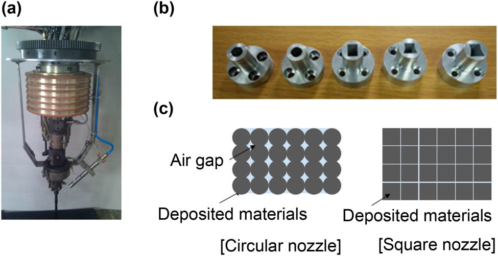
Design of nozzle and extrusion head. (a) Actual picture of the extrusion head, (b) various shapes of the nozzle, (c) illustration of a cross-sectional view of deposited materials from the nozzle. The circular nozzle (left) caused the air gap between the deposited material compared to the square nozzle (right).
2.9 Nozzle
The molten raw materials supplied by a screw are injected through a nozzle at the end of the extruder. The typical FDM-based 3D printers use a circular nozzle to minimize frictional resistance arising from the flow of molten materials. Circular nozzles inevitably cause an air gap between stacked layers (Figure 3a). This is not an important issue in the case of typical FDM-based 3D printers having a small nozzle diameter of about 0.6 mm. However, in the case of large-capacity FDM equipment developed in this study, the nozzle has to be at least 10 mm in diameter to ensure usability in the working speed. In this case, the size of the air gap also increases, and the air gap could negatively impact the product quality and robustness. Various shapes of the nozzle were tested to reduce the air gap (Figure 3b). As a result, we adopted a square nozzle to avoid the air gap formation as schematically illustrated in Figure 3c. On the contrary, if the shape of the nozzle is asymmetrical for rotation such as square, a new problem arises. If the nozzle shape is circular, the sectional shape is identical regardless of the moving direction of the extrusion head. However, the sectional shape is changed by the moving direction if we use a noncircular shape. To solve this problem, we realize the rotation of the nozzle according to the moving direction for obtaining the same sectional head.
2.10 Analysis of extrusion characteristics
The optimal melting temperature and extrusion rate have been validated. Extrusion characteristics were determined by the extrusion rate. When the extrusion rate was too fast, the density of the melting material near the gate of the screw decreased. This low density causes crystallization of the material and increases the shrinkage over time, consequently. Therefore, we determined the optimal extrusion rate and melting temperature to prevent the volumetric change of the feature (Figure 4).

Volumetric change of the feature over time.
2.11 CNC processing unit
The developed large-capacity extruder has a square nozzle with a characteristic dimension of 15 mm, resulting in the limited dimensional accuracy of the same scale. Then, we added an additional mechanical processing unit to improve dimensional accuracy that enables the entire equipment to operate in the hybrid form of 3D printing and machining. The operation of the processing tool may be limited depending on the shape and size; therefore, we adopted a pallet changing operation by which the equipment repeats extrusion and machining in turn as follows: First, the extrusion was conducted according to the geometry limits in which the three-axis head of the machining unit can operate. Then, the deposited structure was machined to the desired shape using machining equipment. A series of processes of the extruder and machining unit were repeated until the final shape was completed. For this purpose, we installed two rails having ball screws along the centerline that transport pallets. Precise positioning of pallets was achieved by the control of the servo motor.
2.12 Tool selection and processing test
After the processing test using various checking tools, we made the following standardized processing sequences and selected tools used in each sequence (Table 1). The processing tools used in the existing wood pattern industry were selected with a high priority for the convenience of workers. After the completion of the machining process, the average surface roughness was obtained with a value of Ra = 2 μm and Ra = 0.2 μm after machining (Figure 5a) and precision polishing (Figure 5b), respectively.

Measurement of roughness after CNC processing. (a) Before CNC processing. (b) After CNC processing. The roughness of the final product is compatible with the commercial wood pattern.
2.13 RPM optimization by materials
To increase the working speed, the maximum number of rotations of the machining tool is desired. However, limiting the rotation speed of the tool is necessary because there is a limitation that the raw material can withstand since a very high RPM will cause the plastic to shave away. Then, the optimization of the machine RPM is required considering the processing time, life span, and roughness of the tool and material characteristics. We conducted a processing test on the polylactic acid (PLA) material varying the machining RPM as 3,000, 2,000, 1,500, and 500. At speeds above 3,000 rpm, a notable fusion of the material occurred along the groove of the tool in a short time, resulting in the processing being impossible. The decrease in the RPM from 3,000 to 2,000 and 1,500 mitigated the fusion of the PLA material; however, the problems in long time processing still arise because of the fusion of material and tool. Then, the RPM <500 was optimal for the PLA material as shown in Figure S2. Increasing the machining speed is necessary for terms of the working speed; in the future, it is desirable to find materials that do not melt with high rotations.
2.14 Development of the CNC control system
We developed the control system for extrusion and machining of equipment using UMCA, a type of processing control system. The control panels for extrusion and machining that can be switched by an internal mode were constructed as shown in Figure S3. If the extrusion/machining g-code is transferred to the mass storage device or network environment, it can be directly operated from the control panel. For simple models, direct pretreatment is also available in the control panel.
2.15 Casting test
To confirm applicability, a casting test was performed if our hybrid system developed in this study could replace the traditional pattern for mold fabrication. The target product is a carriage top having dimensions of 1,600 mm3 × 780 mm3 × 184 mm3 (Figure 6). We checked deformation after extrusion, possible problems in applying mold wash, damage to the plastic pattern in the premolding operation. Figure 6 shows a series of casting processes: extrusion and machining in Figure 6a, complete plastic pattern in Figure 5b, production of sand mold in Figure 6c and the finished product in Figure 6d. Overall, no problem was encountered in the whole process, and the finished prototype was also within the acceptable range in quality inspection.

Actual casting test processes in (a) extrusion and machining, (b) complete plastic pattern, (c) production of the sand mold, and (d) the finished product.
3 Summary
In this article, we have presented the hybrid manufacturing system consisting of a large-scale 3D printer and CNC milling machine for large-scale and high-speed fabrication of patterns for mold making. Our manufacturing system facilitated a newly developed large-capacity extruder with a nozzle area of 15 mm2 × 15 mm2 and an injection velocity of 30 mm·s−1. The dimensional accuracy of large-scale 3D printing is complemented by the CNC machining unit equipped with the LM guide having a transfer accuracy of 1/1,000 mm. The surface roughness of production is a level of Ra = 2 µm, which is compatible with the average surface roughness of the commercial wood pattern. Based on the actual casting test, we concluded that the plastic pattern manufactured by our novel equipment is sufficient to replace the conventional wood pattern in the casting process. We expect that our manufacturing system contributes to reducing costs and increasing productivity as an innovative alternative to conventional mold making in casting.
Acknowledgments
This study has been conducted with the support of the Korea Institute of Industrial Technology as “Development of intelligent root technology with add-on modules (KITECH EO-21-0009).
-
Funding information: This study has been conducted with the support of the Korea Institute of Industrial Technology as “Development of intelligent root technology with add-on modules (KITECH EO-21-0009).”
-
Author contributions: Jeongsu Lee and Jiyoung Song conducted the experiments, performed the implementations and wrote the manuscript. Young Chul Lee conceptualized the study and contributed to experimental work. Jeong Tae Kim supervised the study. All authors contributed to the article and approved the submitted version.
-
Conflict of interest: No potential conflict of interest was reported by the authors.
References
[1] Hawaldar, N. and J. Zhang. A comparative study of fabrication of sand casting mold using additive manufacturing and conventional process. The International Journal of Advanced Manufacturing Technology, Vol. 97, 2018, pp. 1037–1045.10.1007/s00170-018-2020-zSearch in Google Scholar
[2] Ni, Q., W. F. Lu, P. K. Yarlagadda, and X. Ming. Business information modeling for process integration in the mold making industry, Robotics and Computer-Integrated Manufacturing, Vol. 23, No. 2, 2007, pp. 195–207.10.1016/j.rcim.2005.12.006Search in Google Scholar
[3] Tan, L. J., W. Zhu, and K. Zhou. Recent progress on polymer materials for additive manufacturing, Advanced Functional Materials, Vol. 30, No. 43, 2020, id. 2003062.10.1002/adfm.202003062Search in Google Scholar
[4] Bassoli, E., A. Gatto, L. Iuliano, and M. G. Violante. 3D printing technique applied to rapid casting. Rapid Prototyping Journal, Vol. 13, 2007, pp. 148–155.10.1108/13552540710750898Search in Google Scholar
[5] Mohiuddin, M. V., S. F. Hussainy, A. Krishnaiah, and P. Laxminarayana. Experimental investigation to produce thin-walled sand casting using combination of casting simulation and additive manufacturing techniques, The International Journal of Advanced Manufacturing Technology, Vol. 90, No. 9, 2017, pp. 3147–3157.10.1007/s00170-016-9653-6Search in Google Scholar
[6] Walker, J., E. Harris, C. Lynagh, A. Beck, R. Lonardo, B. Vuksanovich, et al. 3D printed smart molds for sand casting. International Journal of Metalcasting, Vol. 12, No. 4, 2018, pp. 785–796.10.1007/s40962-018-0211-xSearch in Google Scholar
[7] Chhabra, M. and R. Singh. Mathematical modeling of surface roughness of castings produced using ZCast direct metal casting, Journal of The Institution of Engineers (India): Series C, Vol. 96, No. 2, 2015, pp. 145–155.10.1007/s40032-014-0139-8Search in Google Scholar
[8] Khosravani, M. R., J. Schüürmann, F. Berto, and T. Reinicke. On the Post-Processing of 3D-Printed ABS Parts. Polymers, Vol. 13, No. 10, 2021, id. 1559.10.3390/polym13101559Search in Google Scholar
[9] Frank, M. C., R. A. Wysk, and S. B. Joshi. Rapid planning for CNC milling—A new approach for rapid prototyping, Journal of Manufacturing Systems, Vol. 23, No. 3, 2004, pp. 242–255.10.1016/S0278-6125(04)80037-2Search in Google Scholar
[10] Shah, J., B. Snider, T. Clarke, S. Kozutsky, M. Lacki, and A. Hosseini. Large-scale 3D printers for additive manufacturing: design considerations and challenges. International Journal of Advanced Manufacturing Technology, Vol. 104, No. 9, 2019, pp. 3679–3693.10.1007/s00170-019-04074-6Search in Google Scholar
[11] Teizer, J., A. Blickle, T. King, O. Leitzbach, and D. Guenther. Large scale 3D printing of complex geometric shapes in construction. ISARC. Proceedings of the International Symposium on Automation and Robotics in. IAARC Publications, Auburn, Alabama, USA, 2016.10.22260/ISARC2016/0114Search in Google Scholar
[12] Gosselin, C., R. Duballet, P. Roux, N. Gaudillière, J. Dirrenberger, and P. Morel. Large-scale 3D printing of ultra-high performance concrete–a new processing route for architects and builders. Materials and Design, Vol. 100, 2016, pp. 102–109.10.1016/j.matdes.2016.03.097Search in Google Scholar
[13] Bos, F., R. Wolfs, Z. Ahmed, and T. Salet. Additive manufacturing of concrete in construction: potentials and challenges of 3D concrete printing. Virtual and Physical Prototyping, Vol. 11, No. 3, 2016, pp. 209–225.10.1080/17452759.2016.1209867Search in Google Scholar
[14] Silver, K., J. Potgieter, K. Arif, and R. Archer. Opportunities and challenges for large scale 3D printing of complex parts. 2017 24th International Conference on Mechatronics and Machine Vision in Practice (M2VIP). IEEE, Auckland: New Zealand, 2017, pp. 1–6.10.1109/M2VIP.2017.8211515Search in Google Scholar
[15] Wang, Z., R. Liu, T. Sparks, and F. Liou. Large-scale deposition system by an industrial robot (I): design of fused pellet modeling system and extrusion process analysis. 3D Printing and Additive Manufacturing, Vol. 3, No. 1, 2016, pp. 39–47.10.1089/3dp.2015.0029Search in Google Scholar
[16] Barnett, E. and C. Gosselin. Large-scale 3D printing with a cable-suspended robot. Additive Manufacturing, Vol. 7, 2015, pp. 27–44.10.1016/j.addma.2015.05.001Search in Google Scholar
[17] Compton, B. G., B. K. Post, C. E. Duty, L. Love, and V. Kunc. Thermal analysis of additive manufacturing of large-scale thermoplastic polymer composites. Additive Manufacturing, Vol. 17, 2017, pp. 77–86.10.1016/j.addma.2017.07.006Search in Google Scholar
[18] Talagani, M. R., S. DorMohammadi, R. Dutton, C. Godines, H. Baid, F. Abdi, et al. Numerical simulation of big area additive manufacturing (3D printing) of a full size car. Sampe Journal, Vol. 51, No. 4, 2015, pp. 27–36.Search in Google Scholar
[19] Nycz, A., V. Kishore, J. Lindahl, C. Duty, C. Carnal, and V. Kunc. Controlling substrate temperature with infrared heating to improve mechanical properties of large-scale printed parts. Additive Manufacturing, Vol. 33, 2020, id. 101068.10.1016/j.addma.2020.101068Search in Google Scholar
[20] Van de Straete, H. J., P. Degezelle, J. De Schutter, and R. J. Belmans. Servo motor selection criterion for mechatronic applications. IEEE/ASME Transactions on Mechatronics, Vol. 3, No. 1, 1998, pp. 43–50.10.1109/3516.662867Search in Google Scholar
[21] Turner, B. N., R. Strong, and S. A. Gold. A review of melt extrusion additive manufacturing processes: I. Process design and modeling. Rapid Prototyping Journal, Vol. 20, No. 3, 2014, pp. 192–204.10.1108/RPJ-01-2013-0012Search in Google Scholar
[22] Trachtenberg, J. E., J. K. Placone, B. T. Smith, C. M. Piard, M. Santoro, D. W. Scott, et al. Extrusion-based 3D printing of poly (propylene fumarate) in a full-factorial design. ACS Biomaterials Science and Engineering, Vol. 2, No. 10, 2016, pp. 1771–1780.10.1021/acsbiomaterials.6b00026Search in Google Scholar PubMed
[23] Buswell, R. A., W. L. De Silva, S. Z. Jones, and J. Dirrenberger. 3D printing using concrete extrusion: a roadmap for research. Cement and Concrete Research, Vol. 112, 2018, pp. 37–49.10.1016/j.cemconres.2018.05.006Search in Google Scholar
[24] Dressler, M., M. Röllig, M. Schmidt, A. Maturilli, and J. Helbert. Temperature distribution in powder beds during 3D printing. Rapid Prototyping Journal, Vol. 16, No. 5, 2010, pp. 328–336.10.1108/13552541011065722Search in Google Scholar
[25] Wolszczak, P., K. Lygas, M. Paszko, and R. A. Wach. Heat distribution in material during fused deposition modelling. Rapid Prototyping Journal, Vol. 24, No. 3, 2018, pp. 615–622.10.1108/RPJ-04-2017-0062Search in Google Scholar
© 2022 Jeongsu Lee et al., published by De Gruyter
This work is licensed under the Creative Commons Attribution 4.0 International License.
Articles in the same Issue
- Research Articles
- Numerical and experimental research on solidification of T2 copper alloy during the twin-roll casting
- Discrete probability model-based method for recognition of multicomponent combustible gas explosion hazard sources
- Dephosphorization kinetics of high-P-containing reduced iron produced from oolitic hematite ore
- In-phase thermomechanical fatigue studies on P92 steel with different hold time
- Effect of the weld parameter strategy on mechanical properties of double-sided laser-welded 2195 Al–Li alloy joints with filler wire
- The precipitation behavior of second phase in high titanium microalloyed steels and its effect on microstructure and properties of steel
- Development of a huge hybrid 3D-printer based on fused deposition modeling (FDM) incorporated with computer numerical control (CNC) machining for industrial applications
- Effect of different welding procedures on microstructure and mechanical property of TA15 titanium alloy joint
- Single-source-precursor synthesis and characterization of SiAlC(O) ceramics from a hyperbranched polyaluminocarbosilane
- Carbothermal reduction of red mud for iron extraction and sodium removal
- Reduction swelling mechanism of hematite fluxed briquettes
- Effect of in situ observation of cooling rates on acicular ferrite nucleation
- Corrosion behavior of WC–Co coating by plasma transferred arc on EH40 steel in low-temperature
- Study on the thermodynamic stability and evolution of inclusions in Al–Ti deoxidized steel
- Application on oxidation behavior of metallic copper in fire investigation
- Microstructural study of concrete performance after exposure to elevated temperatures via considering C–S–H nanostructure changes
- Prediction model of interfacial heat transfer coefficient changing with time and ingot diameter
- Design, fabrication, and testing of CVI-SiC/SiC turbine blisk under different load spectrums at elevated temperature
- Promoting of metallurgical bonding by ultrasonic insert process in steel–aluminum bimetallic castings
- Pre-reduction of carbon-containing pellets of high chromium vanadium–titanium magnetite at different temperatures
- Optimization of alkali metals discharge performance of blast furnace slag and its extreme value model
- Smelting high purity 55SiCr automobile suspension spring steel with different refractories
- Investigation into the thermal stability of a novel hot-work die steel 5CrNiMoVNb
- Residual stress relaxation considering microstructure evolution in heat treatment of metallic thin-walled part
- Experiments of Ti6Al4V manufactured by low-speed wire cut electrical discharge machining and electrical parameters optimization
- Effect of chloride ion concentration on stress corrosion cracking and electrochemical corrosion of high manganese steel
- Prediction of oxygen-blowing volume in BOF steelmaking process based on BP neural network and incremental learning
- Effect of annealing temperature on the structure and properties of FeCoCrNiMo high-entropy alloy
- Study on physical properties of Al2O3-based slags used for the self-propagating high-temperature synthesis (SHS) – metallurgy method
- Low-temperature corrosion behavior of laser cladding metal-based alloy coatings on EH40 high-strength steel for icebreaker
- Study on thermodynamics and dynamics of top slag modification in O5 automobile sheets
- Structure optimization of continuous casting tundish with channel-type induction heating using mathematical modeling
- Microstructure and mechanical properties of NbC–Ni cermets prepared by microwave sintering
- Spider-based FOPID controller design for temperature control in aluminium extrusion process
- Prediction model of BOF end-point P and O contents based on PCA–GA–BP neural network
- Study on hydrogen-induced stress corrosion of 7N01-T4 aluminum alloy for railway vehicles
- Study on the effect of micro-shrinkage porosity on the ultra-low temperature toughness of ferritic ductile iron
- Characterization of surface decarburization and oxidation behavior of Cr–Mo cold heading steel
- Effect of post-weld heat treatment on the microstructure and mechanical properties of laser-welded joints of SLM-316 L/rolled-316 L
- An investigation on as-cast microstructure and homogenization of nickel base superalloy René 65
- Effect of multiple laser re-melting on microstructure and properties of Fe-based coating
- Experimental study on the preparation of ferrophosphorus alloy using dephosphorization furnace slag by carbothermic reduction
- Research on aging behavior and safe storage life prediction of modified double base propellant
- Evaluation of the calorific value of exothermic sleeve material by the adiabatic calorimeter
- Thermodynamic calculation of phase equilibria in the Al–Fe–Zn–O system
- Effect of rare earth Y on microstructure and texture of oriented silicon steel during hot rolling and cold rolling processes
- Effect of ambient temperature on the jet characteristics of a swirl oxygen lance with mixed injection of CO2 + O2
- Research on the optimisation of the temperature field distribution of a multi microwave source agent system based on group consistency
- The dynamic softening identification and constitutive equation establishment of Ti–6.5Al–2Sn–4Zr–4Mo–1W–0.2Si alloy with initial lamellar microstructure
- Experimental investigation on microstructural characterization and mechanical properties of plasma arc welded Inconel 617 plates
- Numerical simulation and experimental research on cracking mechanism of twin-roll strip casting
- A novel method to control stress distribution and machining-induced deformation for thin-walled metallic parts
- Review Article
- A study on deep reinforcement learning-based crane scheduling model for uncertainty tasks
- Topical Issue on Science and Technology of Solar Energy
- Synthesis of alkaline-earth Zintl phosphides MZn2P2 (M = Ca, Sr, Ba) from Sn solutions
- Dynamics at crystal/melt interface during solidification of multicrystalline silicon
- Boron removal from silicon melt by gas blowing technique
- Removal of SiC and Si3N4 inclusions in solar cell Si scraps through slag refining
- Electrochemical production of silicon
- Electrical properties of zinc nitride and zinc tin nitride semiconductor thin films toward photovoltaic applications
- Special Issue on The 4th International Conference on Graphene and Novel Nanomaterials (GNN 2022)
- Effect of microstructure on tribocorrosion of FH36 low-temperature steels