A novel 3D woven carbon fiber composite with super interlayer performance hybridized by CNT tape and copper wire simultaneously
-
Yu Zhu
 ,
Youpei Du
,
Youpei Du

Abstract
In this work, a novel binary hybrid woven carbon nanotube (CNT) tape/copper wire carbon fiber reinforced epoxy resin composite is prepared. The mode I interlaminar fracture toughness (G IC) is employed to critically evaluate the delamination performance. A comparison of the G IC value with that of the carbon fiber reinforced composite confirms that incorporating CNT tapes and copper wires into the composite increases the value by 263%. In the transverse and through-thickness direction, the conductivity of the laminate increases to 458 and 193 S/m, which is increased by 196 and 675%, respectively. The thermal conductivity along the thickness direction is increased to 2.27 W/m K, an increase of 134%. The volume fraction of CNT tapes and copper wire are as low as approximately 0.87 and 0.47 vol%, respectively. 3D woven composites have potential applications in high-performance structures and lightning striking protection such as aircraft, ships, and engines, which benefits by the innovative through-thickness implantation of composites using CNT tape and copper wire.
1 Introduction
Carbon fiber reinforced polymer (CFRP) composites are increasingly utilized in high-performance structures such as aircraft, ships, and engines, owing to their lightweight and superior in-plane mechanical properties [1]. However, the conventional stacking structure of CFRP composites lacks reinforcements in the thickness direction, leading to weaker interlaminar performance and susceptibility to delamination when subjected to out-of-plane loads [2]. Over the past few decades, various methods have been proposed to improve the interlaminar performance of the composites, which could be classified into two categories: (i) interlaminar reinforcement through interlaced lay-up [3,4,5] and toughened nanoparticles [6] and (ii) through-thickness reinforcement, including z-pin [7], stitching [8], and 3D weaving [9]. Carbon nanotube (CNT) film, a two-dimensional self-supporting structure formed by a CNT entangled network of CNTs, is a remarkable material with outstanding mechanical and multifunctional properties. It is considered a vital representative in the field of new flexible continuous reinforcements [10,11].
Currently, the most commonly used method for modifying CFRP with CNT is the interleaving technique. In this method, the CNT film is simply placed between the carbon fiber prepregs, resulting in improved thermoelectric performance both interlaminar and in-plane of the composite [12]. Thostenson et al. [13] demonstrated that electrophoretic deposition of CNTs on carbon fiber fabric before epoxy resin injection can increase the interlaminar shear strength and interlaminar fracture toughness. Zhang et al. [14] developed a spraying technique to deposit CNTs on carbon fiber prepregs, which improved the mode I fracture toughness of carbon fiber laminates increased by about 50% even with a low CNT fraction (0.047 wt%). Liu et al. [15] observed a 74% increase in the G IC of composites by inserting buckypaper into the mid-plane of CFRP using the pressure filtration method. Lewis and Wardle [16] improved the interlaminar shear strength of the composite by 15% by inserting an oriented CNT film made of a roller-pressed vertical CNT array between fabrics.
The Falzon Research Group [17] aminated the highly oriented CNTs film, and the G IC of the composite was increased by 13% by using the short amino chain CNTs film of ethylenediamine. Xu et al. [18] increased the interlaminar shear strength of the composites by 20% by depositing CNT films synthesized on carbon fiber fabrics. At the same time, Ou et al. [19] used the same deposition method to increase the G IC of CNT film interlayer reinforced composites by 60%. However, the methods mentioned above have limitations in terms of CNT films integration with carbon fibers in the thickness direction, where effective connections between CNTs and carbon fibers are lacking. In addition, the CNT film cannot effectively reinforce the Z-direction for mode I opening crack propagation. It is well documented [20] that the 3D fiber weaving method can be applied in Z-direction reinforced polymer to improve the interlaminar properties of the composite. Integrating CNT films with carbon fibers through 3D weaving is a promising approach, but most researchers have overlooked it due to the challenge of introducing CNT film along the through-thickness direction of the fabric.
CNTs exhibit outstanding electrical and thermal conductivity, with the pristine CNT film displaying an in-plane electrical conductivity of 1.5 × 10⁴−1 × 10⁵ S/m [21] and in-plane thermal conductivity ranging from 10–100 W/m K [22]. Researchers have demonstrated that incorporating CNTs into composite structures can enhance the thickness-direction conductivity significantly. For example, Bhanushali and Bradford [23] inserted an aligned CNT film into the middle of the glass fiber composite and reported a 1.3 × 10⁻³ S/m increase in thickness-direction conductivity. Wang et al. [24] achieved a similar outcome by laying the CNT film on each layer of the carbon fiber prepreg, which increased the Z-direction conductivity of the composite from 4 to 21 S/m. Gaztelumendi et al. [25] increased the Z-direction conductivity of the composite by 30% by adding CNT to the resin and inserting buckypaper into the CFRP. Xu et al. [18] laid the continuous CNT film on the carbon fiber fabric, resulting in a 150% increase in the conductivity of the composite in the thickness direction. Currently, CNTs are mainly used to enhance the thermal conductivity of composites by either mixing them with the resin or depositing them on the carbon fiber fabric. This approach has resulted in a 10–35% improvement in the Z-direction thermal conductivity of the prepared composites [26–29]. However, the conventional CNT interlayer reinforced composite is not well-suited to meet the urgent demands of aircraft, engines, and electrical systems for lightning protection, thermal management, and electromagnetic compatibility despite the outstanding multifunctional capabilities of CNTs in the composite structure.
This work introduces a novel method of weaving composite laminates using CNT films. Narrow strips of CNT film are arranged along the thickness direction to reinforce all interlaminar regions between adjacent layers and establish electrical and thermal conduction pathways. To fully utilize the composite’s weaving space by designing the weaving pattern, the flexible copper wire is further woven between the adjacent narrow CNT tapes. By combining CNT tape and copper wire, binary-reinforced woven composites are produced, which enhance the interlaminar mechanical properties and thickness direction electrical and thermal conductivities of carbon fiber composites. This approach represents a promising avenue for the design and development of new composites with three-dimensional reinforced structures and integrated functions.
2 Experimental method
2.1 Materials
A unidirectional (UD) MH-I-300 carbon fiber fabric was supplied by Shanghai Miaohan Co., China. The areal density of the fabric is 300 ± 5 g/m2, and the thickness of a single layer is 0.16 mm. The diameter of copper wire is 0.3 mm. CNT film synthesized by FCCVD method was provided from Suzhou Institute of Nanotechnology and Nano-bionics, Chinese Academy of Sciences. The as-received CNT film was made up of entangled multiwall CNTs with a thickness of approximately 20 μm. In this work, the CNT films were all treated by using m-chloroperoxybenzoic acid (m-CPBA) before it is woven with CFRP. The details of the chemical treatment process were described in our previous studies [30,31]. The mechanical properties of CNT film and copper wire are shown in Table 1. CNT films possess superior tensile strength and modulus, while copper wires have higher ductility.
Mechanical properties of CNT film and copper wire
| Density (g/cm3) | Tensile strength (MPa) | Tensile modulus (GPa) | Fracture strain (%) | |
|---|---|---|---|---|
| CNT filma | 1.38 ± 0.2 | 281 ± 34 | 11.7 ± 0.3 | 10.4 ± 1.3 |
| Copper wire | 8.94 ± 0.1 | 220 ± 5 | 3.31 ± 0.2 | 23.2 ± 3.2 |
aCNT film has been treated with m-CPBA and E51 epoxy resin.
2.2 Fabrication of 3D woven composites
The CNT film treated with m-CPBA was cut into several strips with a size of 8 mm × 400 mm. 20 plies of UD carbon fabric were stacked, and a 13 μm PTFE film was placed in the mid-plane of the fabrics to serve as the starting points for delamination of the double cantilever beam (DCB) test. The weaving process was carried out by the following steps: (i) The CNT tape was pasted on the tail of the special blade with the same width as the tape. (ii) The CNT tape was woven along the thickness direction on the stacked UD carbon fiber fabrics. Moreover, alignment between the gaps of each layer of fiber bundle in multilayer carbon fiber UD fabric by placing a series of fixing sheet. (iii) Using two grippers to clamp the two ends of the multi-layer carbon fiber and UD fabric separately. The CNT tapes have been stitched along the gaps between carbon fibers by using the special blade. We should be very careful to ensure that the CNT tapes pass through the area between the fiber tows to minimize possible damage to the carbon fibers during the weaving process. (iv) The above steps should be repeated to weave of the remaining CNT tapes and the interval between the adjacent CNT. (v) The copper threads were woven on both sides of the CNT tapes by using sewing needle, and the spacing between adjacent copper threads was 10 mm. The weaving patterns of CNT tapes, copper wires, CNT tapes/copper wires 3D woven composites are shown in Figure 1. The volume content of CNT is 0.87 vol%, and that of copper is 0.47 vol%.

Schematic illustration of stitching patterns about 3D CNT strips, copper threads, and CNT strips/copper threads woven composites.
The E51 epoxy resin and curing agent BC12 were prepared in the mass ratio of 100:84. The prepregs were obtained by vacuum-assisted resin infusion method, as shown in Figure 2. The infusion temperature was maintained at 40°C. At this temperature, the viscosity of the resin mixture is 0.25 Pa s. The prepregs were cured by hot-pressing after 10 min resin infusion. This includes first heating from room temperature to 80°C and holding for 30 min, then increasing the temperature to 120°C with a pressure of 0.5 MPa and holding for 180 min, with a heating slope controlled at 1°C/min.

Schematic illustration of vacuum-assisted resin infusion method.
2.3 Characterization methods
2.3.1 Interlaminar properties test method
Mode I interlaminar fracture toughness was measured based on the DCB test according to ASTM D5528. Aluminum loading blocks were bonded to the upper and lower sides at one end of the specimens such that the initial crack length, a 0, was set to 50 mm with reference to the inserted thin PTFE film. The DCB specimens were tested at a crosshead speed of 1 mm/min using Instron 3344 with a 2 kN loading cell. The test fracture data were recorded in the form of load–displacement curves and load-displacement values under different crack lengths. The mode I energy release rate can be expressed by equation (1) as follows:
where P is the load, δ is the opening displacement, a is the total interlaminar crack length, b is the width of the DCB specimen, Δ is the a-axis intercept of the fitted straight line of a–C 1/3, and C = δ/P. F is the large displacement correction coefficient, which can be calculated by equation (2), t is the distance from the center of the loading blocks to the mid-layer of the laminates. The initiation G IC values refer to the critical load and displacement associated with the first deviation (deviation point) from the linear response in the corresponding curve.
The bridging traction law of the mode I opening crack in the Z-direction reinforcement is measured by the bridging traction load test. The sample consists of two parts of composite laminates, and the middle layer is separated by PTFE film, as shown in Figure 3b. The sample size is 30 mm × 25 mm, including 2 × 8 Z-direction reinforcement array made of CNT tape, copper wire, or CNT tape/copper wire. The sample was tested by Instron 3344 using a 2 kN loading cell. The crack of the sample opens at a tensile rate of 1 mm/min until all Z-direction reinforcements fail.

Geometric specifications of experimental specimens: (a) for the DCB test and (b) for the bridging traction load test.
2.3.2 Conductivity tests
The conductivity of composites was tested by a TH2512 DC resistance tester. The copper foil was pasted on the opposite sides of the composite with silver glue to ensure a good connection between the electrode and the sample. The X-, Y- and Z-directions of the composites were tested, and the corresponding conductivities were calculated.
The thermal diffusivities α of the composites were measured at 25°C using a Netzsch LFA-467 MicroFlash laser flash analyzer according to ASTM E1461. Cylindrical specimens in the X- and Y-directions with a diameter of 12.7 mm and a thickness of 4 mm were made by the transposition method [32]. Thermal conductivity λ can be calculated by equation (3) as follows:
where C P is the specific heat of the composite, which is measured by Netzsch STA449F5 in a nitrogen atmosphere. ρ C is the bulk density of the composite measured by ME104 balance according to Archimedes law. Infrared thermal imager FOTRIC 226-3 was used to monitor the heat transfer process of the composites. A ceramic heater with a power of 2 W was pasted on the surface of the sample. The sample was heated uniformly at 25°C. The internal heat conduction behavior of the composite was analyzed by observing the temperature change at the cross-section of the sample.
3 Result and discussion
3.1 Interlaminar properties of 3D woven composite
During mode I crack propagation, the load–displacement curves of control samples, CNT–CFRP, Cop–CFRP, and CNT/Copper–CFRP are presented in Figure 4a. The load–displacement curves of all four samples can be divided into two regions: linear and nonlinear region. After the crack contacts the first vertical mark past the pre-crack tip, the load and displacement values that correspond to the initial value of G IC are recorded. In comparison to the control sample, the crack initiation of all three woven composites occurs under higher displacement and load levels. The maximum load of the control sample is 51 N, and the maximum loads of CNT–CFRP and Cop–CFRP are increased to 82 and 94 N, respectively. The maximum load of hybrid woven CNT/Cop–CFRP was further increased to 127 N. Loads of the three woven composites are consistently greater than that of the control sample during the entire DCB test, indicating the significant role of CNT tape and copper wire in interlaminar reinforcement during crack propagation.
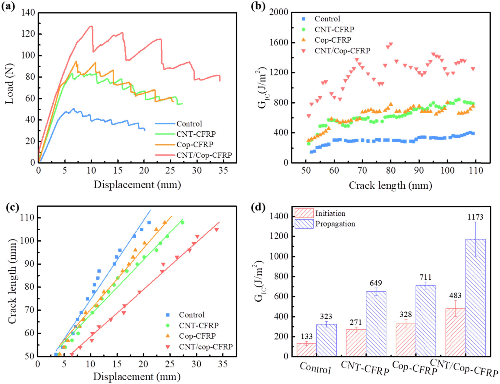
(a) Representative load–displacement curves of the DCB tests, (b) R-curves, (c) displacement–crack length curves, and (d) mode I initiation and propagation fracture toughness values of the control and 3D woven composites, respectively.
In the nonlinear region of the load–displacement curves, the behavior of crack propagation differs for the control sample and the three woven composites, the decline process for the control sample is smooth when the load value reaches its maximum value of 51 N, indicating a stable mid-plane crack propagation. The corresponding initiation and propagation G IC values of control samples are 133 and 323 J/m2, respectively, as shown in Figure 4d and Table 2. For Cop–CFRP, a sawtooth shape in the nonlinear region appears, where the loading value suddenly drops to 82 N as it reaches the peak of 94 N. The serrated load–displacement curve indicates that the crack propagation in Cop–CFRP exhibits obvious stick-slip behavior, characterized by periodic propagation and stop. The crack propagated rapidly after copper wire failure, leading to a sudden drop in load. The load then rises, indicating that the crack tip is captured by the next row of copper wires. The initiation and propagation G IC values of Cop–CFRP are increased to 328 and 711 J/m2, respectively. The enhancement of mode I interlaminar fracture toughness of CNT–CFRP is comparable to that of Cop–CFRP. Li et al. [33] enhanced G IC of laminated composites by 62.5% after CNT belt stitching. Compared with the control sample, the propagation G IC value of CNT–CFRP increased by 101% in this work.
Interlaminar properties of control laminate and 3D woven composites
| Maximum load (N) | Slope | Initiation G IC (J/m2) | Amplification (%) | Propagation G IC (J/m2) | Amplification (%) | |
|---|---|---|---|---|---|---|
| Control | 51 | 3.41 | 133 | — | 323 | — |
| CNT–CFRP | 82 | 2.37 | 271 | 104 | 649 | 101 |
| Cop–CFRP | 94 | 2.64 | 328 | 146 | 711 | 120 |
| CNT/Cop–CFRP | 127 | 2.03 | 483 | 263 | 1,173 | 263 |
In addition, the load drop in the load–displacement curve of CNT–CFRP decreased from 12 N of Cop–CFRP to 7 N due to the CNT tape spacing of only 2 mm. When the last row of CNT tapes failed, the crack tip was timely captured by the next row of CNT tapes before rapid propagation. This capture behavior shortens the crack propagation length and reduces the load drop accordingly. The initiation and propagation G IC values of CNT/Cop–CFRP are increased to 483 and 1,173 J/m2, respectively. Lombetti and Skordos [34] improved the mode I interlaminar fracture toughness of the composites by approximately 200% through copper tufting. However, the weight of copper tufts was 1,000 g/m2 [35]. Compared with the control sample, the propagation G IC of CNT/Cop–CFRP with only 168 g/m2 of the copper wire increased by 263%, which benefits from the ultra-low density of CNT tape. Interestingly, the load–displacement curve of CNT/Cop–CFRP appears to have the most obvious sawtooth profile. The load drop of each crack sudden propagation in CNT/Cop–CFRPdecreases by 24 N.
The crack resistance curves, also known as R-curves, of the control samples and three types of woven composites, CNT–CFRP, Cop–CFRP, and CNT/Cop–CFRP, are shown in Figure 4b. The increase in fracture toughness of the control sample was attributed to the fiber bridging effect caused by the in-plane carbon fibers, which is well documented in the DCB testing and leads to an increase in mode I fracture toughness. In the process of crack propagation, when the number of bridging fibers per unit crack area is equal, the steady-state fracture toughness can eventually be measured, which is denoted as the propagation G IC value. Compared with the control sample, the initiation and propagation G IC of the three types of woven composites are significantly improved, indicating that CNT tape and copper wire improve the delamination resistance of the composites. The G IC values of CNT–CFRP and Cop–CFRP are consistently similar during crack propagation, indicating that CNT tape and copper wire have an equivalent interlaminar reinforcement effect. The G IC values of CNT–CFRP are more stable compared to Cop–CFRP. The highest G IC value is observed in CNT/Cop–CFRP due to the combined toughening effect of the CNT tape and copper wire.
The relationship between the displacement and crack length of the four composites is illustrated in Figure 4c. The slope of the fitting line represents the resistance to crack propagation. The slopes for the control samples, CNT–CFRP, and Cop–CFRP are 3.41, 2.37, and 2.64, respectively. The introduction of CNT tape and copper wire enhances the delamination resistance and improves mode I interlaminar fracture toughness. The slope of CNT/Cop–CFRP further decreases to 2.03 due to the combined effect of CNT tape and copper wire, which is consistent with the R-curve results in Figure 4b.
Figure 5 displays the crack morphologies in the composite section of the control sample and CNT/Cop–CFRP. The crack in the control sample appears as a smooth straight line, while the CNT/Cop–CFRP shows a zigzag crack. The z-filament obstructs the crack, causing it to deflect. The tortuous crack propagation in CNT/Cop–CFRP significantly improves the surface energy, resulting in much higher G IC values of CNT/Cop–CFRP than those of the control sample throughout the entire crack propagation process (Figure 4b).

The cross view of the crack of (a) control sample and (b) CNT/Cop-CFRP.
To further investigate the failure modes of copper wire and CNT tape during DCB testing, the failure morphologies of these z-filaments after crack propagation were observed by SEM. Figure 6 illustrates the failure modes of the copper wire during the crack opening. Two modes of failure were observed in copper wire: pullout failure at the corner and fracture failure in the mid-plane. As the crack opening displacement increased, the copper wire bridged the traction load, resulting in a significantly higher maximum load for Cop–CFRP than for the control sample. The oblique fracture of the copper wire depicted in Figure 6e reflects the characteristics of metal shear failure. As the two laminates were further separated, the copper wire was bonded from the surrounding laminate and pulled out of the laminate, resulting in corresponding holes in the laminate on the other side (Figure 6f). The other part of the copper wire without debonding will undergo a series of behaviors: elastic deformation, plastic deformation, necking, and finally fracture under tensile load. Figure 6d clearly shows the typical necking and tensile fracture surfaces of copper wires broken in the mid-plane. Both failure modes absorb the energy during crack propagation and effectively improve the interlaminar fracture toughness. However, copper wire is a point-reinforced z-filament. Copper wire fitfully provides a bridging traction load, which results in the stick-slip behavior of crack propagation in CFRP, as shown in Figure 4a.

Schematic illustration (a–c) of the failure modes of the copper wire during the crack opening and corresponding SEM failure morphologies (d–f).
The failure mode of CNT tape differs from that of copper wire as it experiences only mid-plane fracture failure, as depicted in Figure 7a. The contact area between a single CNT tape and the laminate is notably larger, approximately 32 mm2, compared to that between copper wire and the laminate, which is only 3.77 mm2. Moreover, due to the good compatibility between nanotubes and resin in CNT tapes, CNT tapes fracture without debonding during crack propagation [36]. Figure 7e shows the clear boundary between random CNTs and oriented CNTs, which indicates that the CNT tape has the slip and orientation of CNTs under stress induction. With the further increase in the opening displacement, the CNTs are pulled out, resulting in the tensile breakage of the CNT tape. Figure 7d shows the characteristic tensile fracture surface of the CNT tape. Some pullout CNTs are observed on the fracture surface (Figure 7f). As the CNT tape provides bridging traction load, the CNTs are oriented, slid, and pulled out in turn among the CNT tape. These behaviors require more energy for crack propagation, resulting in an increase in the G IC value of CNT–CFRP. Although the enhancement in mode I interlaminar fracture toughness by CNT tape is similar to that by copper wire, CNT tape as linear reinforced z-filament can continuously provide traction load during crack propagation. Compared to Cop–CFRP, CNT–CFRP exhibits more stable G IC values during the DCB test, as depicted in Figure 4b.

Schematic illustration (a–c) of the failure mode of CNT tape during the crack opening and the corresponding SEM failure morphologies (d–f).
Figure 8 shows the mode I crack bridging traction load–crack opening displacement curves for three types of 3D woven composites: CNT–CFRP, Cop–CFRP, and CNT/Cop–CFRP. Initially, the CNT tape in the through-thickness direction of CNT–CFRP deforms elastically before reaching the maximum load of 177 N. Beyond this point, the crack traction load drops rapidly; this is due to the slippage and orientation of the CNTs, which leads to their pull out from the fracture surface leading to the fracture of the CNT tape in the through-thickness direction. In the mode I interlaminar fracture toughness test for Cop–CFRP, two fracture modes of copper wire have been identified: the initial shear fracture near the outer surface of the composite and the following tensile fracture at the delamination plane, as shown in Figure 6. The maximum traction load for Cop–CFRP is 215 N, and after shear fracture of some copper wires near the outer surface occurs, there is a sharp decrease in the traction load to 75 N. However, due to the friction generated during the pullout of the copper wires, the traction load decreases only slightly to 68 N as the opening displacement increases from 1.08 to 1.16 mm. With a further increase in opening displacement, the traction load decreases rapidly because unbroken copper wires fracture at the delamination plane. For CNT/Cop–CFRP, as the CNT tape and copper wire provide the traction load together, the maximum peak load of CNT/Cop–CFRP is greatly increased to 369 N in comparison with 177 N of CNT–CFRP and 215 N of Cop–CFRP, and this accounts in part for the experimentally measured highest toughening effect by CNT/Cop–CFRP in DCB test. The maximum load of CNT/Cop–CFRP is slightly less than the sum of that of Cop–CFRP and CNT–CFRP, which is in accordance with the relationship of propagation G IC values in Figure 4d. CNT tape and copper wire are difficult to display the superposition enhancement on providing bridging traction load because of the different tensile modulus and fracture strain of copper wire and CNT tape. Beyond the maximum point, the traction load decreases due to the fracture of CNT tape in the Z-direction. When the opening displacement further increases to 0.82 mm, the shear fracture of copper wires near the outer surface occurs. This leads to the rapid decrease in the traction load from 352 to 187 N. When the copper wires break near the outer surface, they are gradually pulled out of the composite with further increased opening displacement leading to improved fracture toughness. Hence, when the opening displacement increases from 0.91 to 1.1 mm, the traction load drops only slightly from 189 to 172 N. Finally, the occurrence of tensile fracture of copper wires at the delamination plane brings about a sharp decrease in the traction load as the opening displacement passes 1.1 mm.

Mode I crack bridging traction load–crack opening displacement curves for the different through-thickness reinforcements.
3.2 Electrical and thermal conductivities
Table 3 presents the volume electrical conductivity values in three directions, namely, the fiber direction (X-direction), transverse direction (Y-direction), and through-thickness direction (Z-direction). The X-direction conductivity remained unchanged for all three 3D woven composites, as the CNT tapes and copper wires did not provide a continuous pathway for current flow in this direction. On the contrary, the X-direction electrical conductivity marginally decreased due to the misalignment or breakage of carbon fibers caused by the 3D weaving process. However, the Y- and Z-direction electrical conductivity of the two 3D woven composite laminates, i.e., CNT–CFRP and Cop–CFRP, significantly improved compared to the control specimen. The trend of the conductivity of the two 3D woven composites, i.e., CNT–CFRP and Cop–CFRP corresponds to the conductivity reported for the CNT tape (4.2 × 10⁴ S/m) and copper wire (5.6 × 10⁷ S/m). In contrast with CNT–CFRP and Cop–CFRP, the highest electrical conductivity in the transverse (458 S/m) and through-thickness direction (193 S/m) was achieved for CNT/Cop–CFRP with the volume fraction of copper wire as low as approximately 0.47 vol%. Actually, this percentage of copper wire can, if wished, still be increased, leading to more improvement in the transverse and through-thickness direction electrical conductivity of the two fabricated composites, i.e., Cop–CFRP and CNT/Cop–CFRP. The literature [37] showed that through-thickness electrical conductivity of 74 S/m CFRP is sufficient to provide resistance to lightning strikes. The fabricated composite viz Cop–CFRP significantly exceeds this threshold value even with a very low volume content of 0.47 vol% of copper wires. Therefore, this approach presents opportunities to eliminate the need for the sacrificial metal layers commonly employed for lightning strike protection of aircraft, although UD carbon fiber fabric was used in this study. It is worth noting that the weight of copper wires in the composite is only 168 g/m2, which is smaller than the weight of 195 g/m2 of common copper meshes used for lightning strike protection.
Electrical and thermal conductivities of control laminate and 3D woven composites
| Electrical conductivity (S/m) | Thermal conductivity (W/m K) | |||||
|---|---|---|---|---|---|---|
| X-direction | Y-direction | Z-direction | X-direction | Y-direction | Z-direction | |
| Control | 3,139 ± 106 | 155 ± 13 | 24.9 ± 2.7 | 7.26 ± 0.7 | 0.96 ± 0.1 | 0.97 ± 0.1 |
| CNT–CFRP | 2,807 ± 83 | 251 ± 27 | 48.7 ± 4.2 | 8.31 ± 0.5 | 1.02 ± 0.1 | 1.09 ± 0.1 |
| Cop–CFRP | 3,105 ± 112 | 381 ± 21 | 154 ± 12 | 8.75 ± 0.6 | 1.11 ± 0.2 | 1.64 ± 0.1 |
| CNT/Cop–CFRP | 2,067 ± 75 | 458 ± 39 | 193 ± 11 | 7.12 ± 0.5 | 1.31 ± 0.1 | 2.27 ± 0.2 |
Achieving high values of thermal conductivity in structural composites is a primary goal in thermal management applications, particularly in the through-thickness direction. In this research, a novel weaving method was developed to provide a direct conductive pathway along the through-thickness direction for achieving high thermal conductivity. Incorporating CNT tapes and copper wires, which have inherently high thermal conductivity, increased the through-thickness thermal conductivity of CFRP. The Y- and Z-direction thermal conductivity of carbon fiber/epoxy laminates incorporating CNT tapes and copper wires at a combined loading of 1.34 vol% was significantly higher (Y-direction: 37%, Z-direction: 134%) than what can be achieved by using CNT tapes (Y-direction: 6%, Z-direction: 12%) or copper wires (Y-direction: 16%, Z-direction: 69%) alone, as shown in Table 1. Copper wire was found to be more effective than CNT tape in increasing the through-thickness thermal conductivity of carbon fiber/epoxy laminates. The researchers did not include a sample with higher amounts of copper wire, as their focus was to demonstrate the idea of increased through-thickness electrical conductivity using copper wire and its effectiveness. However, it can be expected that increasing the amount of copper wire will result in a considerable improvement in the through-thickness thermal conductivity.
In order to investigate the heat transfer process in 3D woven composites using CNT tape and copper wire, we analyzed the dynamic heat transfer of control samples, CNT–CFRP, and Cop–CFRP. Figure 9a illustrates the dynamic heat transfer process of the three composite types along the Z-direction. For the control sample, heat gradually diffuses upwards over time, and the temperature field becomes uniform at 200 s. The bright high-temperature zone observed between layers is caused by the heat transfer of weft-knitted polyester fiber. In CNT–CFRP, a clear, bright zone passing through the Z-direction is observed at 30 s, indicating that the CNT tape has established a conductive pathway through the thickness direction of the composite. More significantly, the bright high-temperature area of Cop–CFRP is considerably larger than that of the other two samples at 10 s. The brightness and width of the high-temperature zone are significantly improved compared to CNT–CFRP, indicating that copper wire has higher heat transfer efficiency. The dark spot in the section represents a part of the copper wire exposed on the surface, which rapidly exchanges heat with the air, keeping the area at room temperature. When the temperature field is stable (200 s), the maximum temperature of the Cop–CFRP is 65°C, which is lower than the steady-state temperature of 70°C of the other two samples. These results partly explain why the Cop–CFRP and CNT/Cop–CFRP with copper wire have better Z-direction thermal conductivity.
Figure 9b shows the dynamic heat transfer process along the Y-direction. Due to the barrier of carbon fiber bundles, CNT tapes, and copper wires are difficult to form a continuous conduction path in the Y-direction. The reinforcement only radiates heat to the surrounding laminate, resulting in the enhancement of thermal conductivity in the Y-direction being weaker than that in the Z-direction.
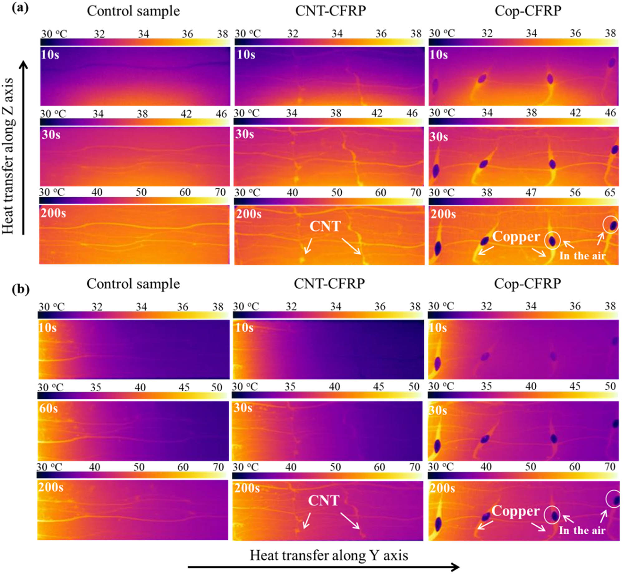
Heat transfer process through the thickness of control sample, CNT–CFRP, and Cop–CFRP.
4 Conclusion
Inspired by weaving techniques, this study proposed a novel method of weaving composite laminates using CNT tapes arranged in the thickness direction to strengthen interlaminar regions between adjacent layers and establish electrical and thermal conduction pathways. To fully utilize the weaving space of the composite, copper wires were also woven between adjacent CNT tapes to create a novel 3D woven carbon fiber composite with super interlayer performance, CNT/Cop–CFRP. A substantial increase in mode I fracture toughness by 263% was observed compared to the control specimen due to the existence of the CNT film and copper wire, which increased the surface energy of crack propagation. Zigzag cracks in the CNT/Cop–CFRP resulted in a series of behaviors, such as elastic and plastic deformation, shear fracture at the corner, tensile fracture at the mid-plane in the copper wire, as well as orientation, slippage, and pull-out of CNT tapes. These behaviors significantly improved the mode I interlaminar fracture toughness of the laminates by providing bridging traction load and absorbing energy. Furthermore, the through-thickness electrical and thermal conductivity of CNT/Cop–CFRP increased by 675 and 134%, respectively, from the control specimen, from 24.9 S/m and 0.97 W/m K to 193 S/m and 2.27 W/m K, with a low volume fraction of copper wire of approximately 0.47 vol%. 3D woven composites has potential applications in high-performance structures and lightning striking protection such as aircraft, ships, and engines, owing to their superior interlaminar mechanical properties, and electrical and thermal conductivities. However, 3D woven carbon fiber composite materials can only be manually manufactured due to the special weaving method of CNT tapes. The CNT yarn and mechanized weaving methods will be attempted in future work to meet the needs of industrial scale.
-
Conflict of interest: The authors state no conflict of interest.
-
Data availability statement: The data presented in this study are available on request from the corresponding author.
References
[1] Prashanth BHM, Gouda PSS, Manjunatha TS, Banapurmath NR, Edacheriane A. Understanding the impact of fiber orientation on mechanical, interlaminar shear strength, and fracture properties of jute–banana hybrid composite laminates. Polym Compos. 2021;42(10):5475–89.10.1002/pc.26239Search in Google Scholar
[2] Arai M, Hirokawa JI, Hanamura Y, Ito H, Hojo M, Quaresimin M. Characteristic of mode I fatigue crack propagation of CFRP laminates toughened with CNF interlayer. Compos B Eng. 2014;65(oct):26–33.10.1016/j.compositesb.2014.02.025Search in Google Scholar
[3] Wang X, Melly SK, Li N, Wang G-D, Peng T, Li Y, et al. Helical milling response of glass fiber-reinforced polymer composite with carbon nanotube buckypaper interlayer. Polym Polym Compos. 2019;28(6):378–87.10.1177/0967391119879296Search in Google Scholar
[4] Cao D, Malakooti S, Kulkarni VN, Ren Y, Lu H. The effect of resin uptake on the flexural properties of compression molded sandwich composites. Wind Energy. 2022;25(1):71–93.10.1002/we.2661Search in Google Scholar
[5] Cao D, Malakooti S, Kulkarni VN, Ren Y, Lu H. Nanoindentation measurement of core–skin interphase viscoelastic properties in a sandwich glass composite. Mech Time-Depend Mater. 2021;25(3):353–63.10.1007/s11043-020-09448-ySearch in Google Scholar
[6] Ravindran AR, Ladani RB, Wang CH, Mouritz AP. Hierarchical mode I and mode II interlaminar toughening of Z-pinned composites using 1D and 2D carbon nanofillers. Compos Part A Appl Sci Manuf. 2019;124:105470.10.1016/j.compositesa.2019.05.038Search in Google Scholar
[7] Mouritz AP. Review of z-pinned laminates and sandwich composites. Compos Part A Appl Sci Manuf. 2020;139:106128.10.1016/j.compositesa.2020.106128Search in Google Scholar
[8] Plain KP, Tong L. An experimental study on mode I and II fracture toughness of laminates stitched with a one-sided stitching technique. Compos Part A Appl Sci Manuf. 2011;42(2):203–10.10.1016/j.compositesa.2010.11.006Search in Google Scholar
[9] Fishpool DT, Rezai A, Baker D, Ogin SL, Smith PA. Interlaminar toughness characterisation of 3D woven carbon fibre composites. Plast Rubber Compos. 2013;42(3):108–14.10.1179/1743289812Y.0000000036Search in Google Scholar
[10] Khan SU, Kim J-K. Improved interlaminar shear properties of multiscale carbon fiber composites with buckypaper interleaves made from carbon nanofibers. Carbon. 2012;50(14):5265–77.10.1016/j.carbon.2012.07.011Search in Google Scholar
[11] Wang X, Xu T, de Andrade MJ, Rampalli I, Cao D, Haque M, et al. The interfacial shear strength of carbon nanotube sheet modified carbon fiber composites. vol. 2, Cham: Springer International Publishing; 2021. p. 25–32.10.1007/978-3-030-59542-5_4Search in Google Scholar
[12] Shin YC, Kim SM. Enhancement of the interlaminar fracture toughness of a carbon-fiber-reinforced polymer using interleaved carbon nanotube buckypaper. Appl Sci. 2021;11(15):6821.10.3390/app11156821Search in Google Scholar
[13] Bekyarova E, Thostenson ET, Yu A, Kim H, Haddon RC. Multiscale carbon nanotube-carbon fiber reinforcement for advanced epoxy composites. Langmuir ACS J Surf Colloids. 2007;23(7):3970.10.1021/la062743pSearch in Google Scholar PubMed
[14] Zhang H, Liu Y, Kuwata M, Bilotti E, Peijs T. Improved fracture toughness and integrated damage sensing capability by spray coated CNTs on carbon fibre prepreg. Compos Part A Appl Sci Manuf. 2015;70:102–10.10.1016/j.compositesa.2014.11.029Search in Google Scholar
[15] Liu L, Shen L, Zhou Y. Improving the interlaminar fracture toughness of carbon/epoxy laminates by directly incorporating with porous carbon nanotube buckypaper. J Reinf Plast Compos. 2015;35(2):1–10.10.1177/0731684415610919Search in Google Scholar
[16] Lewis D, Wardle BL. Interlaminar shear strength investigation of aligned carbon nanotube-reinforced prepreg composite interfaces. AIAA/ASCE/AHS/ASC Structures, Structural Dynamics, & Materials Conference. 2013.Search in Google Scholar
[17] Nistal A, Falzon BG, Hawkins SC, Chitwan R, García-Diego C, Rubio F. Enhancing the fracture toughness of hierarchical composites through amino-functionalised carbon nanotube webs. Compos B Eng. 2019;165:537–44.10.1016/j.compositesb.2019.02.001Search in Google Scholar
[18] Xu H, Tong X, Zhang Y, Li Q, Lu W. Mechanical and electrical properties of laminated composites containing continuous carbon nanotube film interleaves. Compos Sci Technol. 2016;127:113–8.10.1016/j.compscitech.2016.02.032Search in Google Scholar
[19] Ou Y, González C, Vilatela JJ. Interlaminar toughening in structural carbon fiber/epoxy composites interleaved with carbon nanotube veils. Compos Part A Appl Sci Manuf. 2019;124:105477.10.1016/j.compositesa.2019.105477Search in Google Scholar
[20] Tong L, Mouritz AP, Bannister MK, editors. 3D fibre reinforced polymer composites. Oxford: Elsevier Science; 2002. p. 219–36.10.1016/B978-008043938-9/50017-XSearch in Google Scholar
[21] Xie XL, Mai YW, Zhou XP. Dispersion and alignment of carbon nanotubes in polymer matrix: A review. Mater Sci Eng R Rep. 2005;49(4):89–112.10.1016/j.mser.2005.04.002Search in Google Scholar
[22] Kim P, Shi L, Majumdar A, Mceuen PL. Thermal transport measurements of individual multiwalled nanotubes. PhRvL. 2001;87(21):215502.10.1103/PhysRevLett.87.215502Search in Google Scholar PubMed
[23] Bhanushali H, Bradford PD. Woven glass fiber composites with aligned carbon nanotube sheet interlayers. J Nanomater. 2016;2016:9705257.10.1155/2016/9705257Search in Google Scholar
[24] Wang S, Downes R, Young C, Haldane D, Hao A, Liang R, et al. Carbon fiber/carbon nanotube buckypaper interply hybrid composites: Manufacturing process and tensile properties. Adv Eng Mater. 2015;17(10):1442–53.10.1002/adem.201500034Search in Google Scholar
[25] Gaztelumendi I, Chapartegui M, Seddon R, Flórez S, Pons F, Cinquin J. Enhancement of electrical conductivity of composite structures by integration of carbon nanotubes via bulk resin and/or buckypaper films. Compos B Eng. 2017;122:31–40.10.1016/j.compositesb.2016.12.059Search in Google Scholar
[26] Wang B, Fu Q, Yin T, Li H, Qi L, Fu Y. Grafting CNTs on carbon fabrics with enhanced mechanical and thermal properties for tribological applications of carbon fabrics/phenolic composites. Carbon. 2018;139:45–51.10.1016/j.carbon.2018.06.032Search in Google Scholar
[27] Rana S, Alagirusamy R, Joshi M. Development of carbon nanofibre incorporated three phase carbon/epoxy composites with enhanced mechanical, electrical and thermal properties. Compos Part A Appl Sci Manuf. 2011;42(5):439–45.10.1016/j.compositesa.2010.12.018Search in Google Scholar
[28] Zakaria MR, Md Akil H, Omar MF, Abdul Kudus MH, Mohd Sabri FNA, Abdullah MMAB. Enhancement of mechanical and thermal properties of carbon fiber epoxy composite laminates reinforced with carbon nanotubes interlayer using electrospray deposition. Compos C Open Access. 2020;3:100075.10.1016/j.jcomc.2020.100075Search in Google Scholar
[29] Liang J, Saha MC, Altan MC. Effect of carbon nanofibers on thermal conductivity of carbon fiber reinforced composites. Procedia Eng. 2013;56:814–20.10.1016/j.proeng.2013.03.201Search in Google Scholar
[30] Li T, Li M, Gu Y, Wang S, Li Q, Zhang Z. Mechanical enhancement effect of the interlayer hybrid CNT film/carbon fiber/epoxy composite. Compos Sci Technol. 2018;166:176–82.10.1016/j.compscitech.2018.02.007Search in Google Scholar
[31] Zhang M, Li M, Wang S, Wang Y, Zhang Y, Gu Y, et al. The loading-rate dependent tensile behavior of CNT film and its bismaleimide composite film. Mater Des. 2017;117:37–46.10.1016/j.matdes.2016.12.085Search in Google Scholar
[32] Fang Z, Li M, Wang S, Li Y, Wang X, Gu Y, et al. Geometrical effect on thermal conductivity of unidirectional fiber-reinforced polymer composite along different in-plane orientations. ApCM. 2018;25(6):1255–68.10.1007/s10443-017-9664-ySearch in Google Scholar
[33] Li H, Yu Y, Xu X, Chen T, Lu W. Enhancing the fracture toughness of laminated composites through carbon nanotube belt stitching. Compos Sci Technol. 2021;204:108632.10.1016/j.compscitech.2020.108632Search in Google Scholar
[34] Lombetti DM, Skordos AA. Lightning strike and delamination performance of metal tufted carbon composites. Compos Struct. 2019;209:694–9.10.1016/j.compstruct.2018.11.005Search in Google Scholar
[35] Lombetti DM. Tufting of complex composite structures. 2015; 182.Search in Google Scholar
[36] Li M, Wang Z, Liu Q, Wang S, Gu Y, Li Y, et al. Carbon nanotube film/epoxy composites with high strength and toughness. Polym Compos. 2017;38(3):588–96.10.1002/pc.23617Search in Google Scholar
[37] Kumar V, Sharma S, Pathak A, Singh BP, Dhakate SR, Yokozeki T, et al. Interleaved MWCNT buckypaper between CFRP laminates to improve through-thickness electrical conductivity and reducing lightning strike damage. Compos Struct. 2019;210:581–9.10.1016/j.compstruct.2018.11.088Search in Google Scholar
© 2023 the author(s), published by De Gruyter
This work is licensed under the Creative Commons Attribution 4.0 International License.
Articles in the same Issue
- Regular Articles
- Effects of cellulose nanofibers on flexural behavior of carbon-fiber-reinforced polymer composites with delamination
- Damage mechanisms of bismaleimide matrix composites under transverse loading via quasi-static indentation
- Experimental study on hydraulic fracture behavior of concrete with wedge-splitting testing
- The assessment of color adjustment potentials for monoshade universal composites
- Metakaolin-based geopolymers filled with volcanic fly ashes: FT-IR, thermal characterization, and antibacterial property
- The effect of temperature on the tensile properties and failure mechanisms of two-dimensional braided composites
- The influence of preparation of nano-ZrO2/α-Al2O3 gradient coating on the corrosion resistance of 316L stainless steel substrate
- A numerical study on the spatial orientation of aligning fibrous particles in composites considering the wall effect
- A simulative study on the effect of friction coefficient and angle on failure behaviors of GLARE subjected to low-velocity impact
- Impact resistance capacity and degradation law of epoxy-coated steel strand under the impact load
- Analytical solutions of coupled functionally graded conical shells of revolution
- The influence of water vapor on the structural response of asphalt pavement
- A non-invasive method of glucose monitoring using FR4 material based microwave antenna sensor
- Chloride ion transport and service life prediction of aeolian sand concrete under dry–wet cycles
- Micro-damage analysis and numerical simulation of composite solid propellant based on in situ tensile test
- Experimental study on the influence of high-frequency vibratory mixing on concrete performance
- Effects of microstructure characteristics on the transverse moisture diffusivity of unidirectional composite
- Gradient-distributed ZTAp-VCp/Fe45 as new anti-wear composite material and its bonding properties during composite casting
- Experimental evaluation of velocity sensitivity for conglomerate reservoir rock in Karamay oil field
- Mechanical and tribological properties of C/C–SiC ceramic composites with different preforms
- Mechanical property improvement of oil palm empty fruit bunch composites by hybridization using ramie fibers on epoxy–CNT matrices
- Research and analysis on low-velocity impact of composite materials
- Optimizing curing agent ratios for high-performance thermosetting phthalonitrile-based glass fibers
- Method for deriving twisting process parameters of large package E-glass yarn by measuring physical properties of bobbin yarn
- A probability characteristic of crack intersecting with embedded microcapsules in capsule-based self-healing materials
- An investigation into the effect of cross-ply on energy storage and vibration characteristics of carbon fiber lattice sandwich structure bionic prosthetic foot
- Preparation and application of corona noise-suppressing anti-shedding materials for UHV transmission lines
- XRD analysis determined crystal cage occupying number n of carbon anion substituted mayenite-type cage compound C12A7: nC
- Optimizing bending strength of laminated bamboo using confined bamboo with softwoods
- Hydrogels loaded with atenolol drug metal–organic framework showing biological activity
- Creep analysis of the flax fiber-reinforced polymer composites based on the time–temperature superposition principle
- A novel 3D woven carbon fiber composite with super interlayer performance hybridized by CNT tape and copper wire simultaneously
- Effect of aggregate characteristics on properties of cemented sand and gravel
- An integrated structure of air spring for ships and its strength characteristics
- Modeling and dynamic analysis of functionally graded porous spherical shell based on Chebyshev–Ritz approach
- Failure analysis of sandwich beams under three-point bending based on theoretical and numerical models
- Study and prediction analysis on road performance of basalt fiber permeable concrete
- Prediction of the rubberized concrete behavior: A comparison of gene expression programming and response surface method
- Study on properties of recycled mixed polyester/nylon/spandex modified by hydrogenated petroleum resin
- Effect of particle size distribution on microstructure and chloride permeability of blended cement with supplementary cementitious materials
- In situ ligand synthesis affording a new Co(ii) MOF for photocatalytic application
- Fracture research of adhesive-bonded joints for GFRP laminates under mixed-mode loading condition
- Influence of temperature and humidity coupling on rutting deformation of asphalt pavement
- Review Articles
- Sustainable concrete with partial substitution of paper pulp ash: A review
- Durability and microstructure study on concrete made with sewage sludge ash: A review (Part Ⅱ)
- Mechanical performance of concrete made with sewage sludge ash: A review (Part Ⅰ)
- Durability and microstructure analysis of concrete made with volcanic ash: A review (Part II)
- Communication
- Calculation of specific surface area for tight rock characterization through high-pressure mercury intrusion
- Special Issue: MDA 2022
- Vibration response of functionally graded material sandwich plates with elliptical cutouts and geometric imperfections under the mixed boundary conditions
- Analysis of material removal process when scratching unidirectional fibers reinforced polyester composites
- Tailoring the optical and UV reflectivity of CFRP-epoxy composites: Approaches and selected results
- Fiber orientation in continuous fiber-reinforced thermoplastics/metal hybrid joining via multi-pin arrays
- Development of Mg-based metal matrix biomedical composites for acicular cruciate ligament fixation by reinforcing with rare earth oxide and hydroxyapatite – A mechanical, corrosion, and microstructural perspective
- Special Issue: CACMSE
- Preparation and application of foamed ceramic panels in interior design