Investigation on the effect of electrode tip on formation of metal droplets and temperature profile in a vibrating electrode electroslag remelting process
-
Fang Wang
 ,
Jakov Baleta
,
Jakov Baleta

Abstract
In the present work, a transient full-coupled modelling approach has been put forward to study the effect of electrode tip on formation of metal droplets and temperature profile in the electromagnetically-controlled electroslag-remelting furnace with vibrating electrode. The electromagnetic field, momentum and energy conservation equations are solved simultaneously based on the finite volume method. The interface of slag and metal is traced using the volume of fluid approach. The results show that in the case of cone tip electrode the average dimension of metal droplets is smaller compared to the flat tip electrode. In addition, the bigger and stretched metal droplets are not observed with the cone tip electrode. The temperature fields with the cone tip electrode are distributed in a prominent periodic pattern compared to the case with flat tip electrode. The maximum temperature zone with the cone tip electrode is located along the z axial in the upper part of slag, not in the lower part. When the frequency changes from 0.17 Hz to 1 Hz, the maximum temperature reduces from 2050 K to 1985 K and the peak value of velocity decreases from 0.20 m/s to 0.125 m/s. When the vibration amplitude varies from 3mm to 6mm, the maximum temperature in the slag cover drops by 3.9% and the peak value of velocity rises by 16.7%.
1 Introduction
The electroslag remelting (ESR) process is a foundry method to refine and mold molten metals based on the electrical heating technique [1]. The Joule heating generated from the molten slag pool is used to melt the consumable electrode tip. The melting metal droplets at the tip of electrode go through the slag cover and come together in the molten metal pool. And finally they are solidified in the cooling water mold to form the high quality, low defects and segregation ingots [2]. Generally, the performance of ingot is characterized by its surface and internal performance, which depends intensively on the temperature and profile of melting pool [3]. The desired condition of the ESR process is a shallow metal melting pool which elevates unidirectional (upwards) solidification of the metal [4].
In order to improve the efficiency of ESR furnace and the ingot performance, the vibrating electrode electroslag remelting (VE-ESR) process has been proposed. Wang et al. [5] points out the vibrating electrode ESR technique would increase melting rating, improve heat transfer characteristic between electrode and slag, and even raise the temperature in slag layer. Figure 1 shows a schematic of the VE-ESR system.
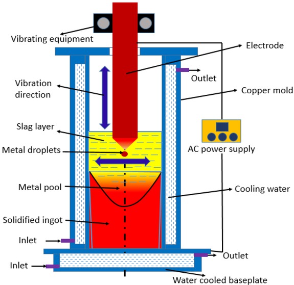
Schematic of the VE-ESR process; the purple arrows represent the direction of horizontal and vertical electrode vibration, respectively
In the ESR process, the electrode tip is supposed to effect the formation of metal droplets, while it will change the shape and size of metal droplets, further dominating the temperature profile in slag [6]. Because the change of the electrode tip dramatically influences the distribution of electrical currents in the slag, and so does the distribution of Joule heating. Furthermore, it has been concerned that the metal pool shape plays an important role on the solute transport and macrosegregation in the ESR ingot [7]. Therefore, the effect of the electrode tip on the formation of metal droplets and temperature field should be systematically understood.
In the past, dedicated amount of work was done by choosing the flat tip electrode in the multi-physical fields. Jiang et al. [8] established a transient 2D axisymmetric numerical model with flat tip electrode to reveal the effect of metal droplets on the electromagnetic field, fluid flow and temperature field in the ESR process. Kharicha et al. [9] studied the influence of the frequency of AC power supply on the magneto-hydrodynamic with flat electrode tip during the traditional ESR process. The influence between the electrochemistry and the droplet formation is discussed. Kelkar et al. [10] studied the effect of the various process parameters on temperature profiles, flow field, and pool shapes with flat electrode tip in the traditional ESR process. Wang Q et al. [11] employed a transient 3D model to understand the role of slag thickness on the formation of metal bath with flat electrode tip in the ESR process. They found that changing the slag thickness could non-monotonically alter the slag temperature. However, they are all discussed about flat electrode tip during the traditional ESR process.
As discussed above, few attempts to systematically discuss the effect of electrode tip on the formation of metal droplets and temperature field in the vibrating electrode ESR furnace are found. In order to put the vibration electrode ESR system into practice, a further parametric study should be conducted. The aim of the present work is to study the effects of electrode tip profile on the formation of metal droplets and temperature field in the VE-ESR process. A transient full-coupled mathematical model with magneto-hydro-dynamic (MHD) multi-phase approach coupled with the dynamic mesh-based method has been established in the electromagnetic-controlled VEESR furnace. In addition, the effect of amplitude and frequency of electrode vibration have been discussed.
2 Mathematic Model
In the paper, the impact of electrode vibration on the electromagnetic field is neglected. The computational domain are composed of the slag and ingot.
The basic electromagnetic equations for the whole zone are as follows:
Ampere’s la:
Faraday’s law:
Gauss’s law:
Continuity of magnetic flux density:
The displacement of electric current is much lower than electric conduction while the frequency is less than 50 Hz [12]. So that Ampere’s law is simplified as:
Ohm’s law:
Lorentz’s law:
Joule’s law: Fluid flow does not effect the magnetic field, as the magnetic Reynolds number keeps lower [13]. Thus, the Ohm’s law has been simplified to
Joule heat generation rate is expressed as:
The flow of the slag and liquid metal are supposed to be turbulent, as previously discussed by Jardy et al. [13] and Kelkar et al. [14]. Hence, it is modeled based on Reynolds-averaged Navier-Stokes equations, through taking apart the local velocity into a mean and a fluctuation value. A standard k-ε turbulent model is employed to solve the turbulent viscosity of the momentum equations as follows:
The volume of fluid (VOF) method presented in ‘FLUENT’ software are introduced since it is a robust, widely applied technique [5]. The user defined function (UDF) and dynamic mesh model are unified to performance the behavior of vibrating electrode.
Where,
The heat transfer and solidification feature in the ESR process are described by the energy conservation equation based on the enthalpy-formulation [16]:
Where, λt denotes the effective thermal conductivity which is inferred from the turbulent viscosity [17], Q Joule is Joule heating.
3 Boundary conditions and solution procedure
At inlet and outlet, the magnetic flux density is continuous and equal to zero near the wall [13] and
Here, the symbol represents the power efficiency. It is hard to decide the power efficiency accurately as to the complex physical and chemical process. Hence, a reasonable power efficiency 0.18 is chosen from literature [18].
A no-slip boundary condition is imposed at the mold walls. The top surface of slag are forced with zero shear stress. Inlet metal temperature profile was drawn with a parabolic shape, which had a 30 K superheat higher than the metal liquidus. Equivalent heat transfer coefficients are applied for the lateral and bottom walls [18, 19]. The key geometrical and material properties together with controlling parameters are shown in Table 1.
The key geometrical, material properties and controlling parameters used in simulation
| Parameter | Value |
|---|---|
| Geometry and operating conditions | |
| Electrode diameter (m) | 0.1 |
| Slag bath depth (m) | 0.12 |
| Immersion depth of electrode (m) | 0.1 |
| Ingot diameter (m) | 0.22 |
| Current (A) | 4500 |
| Frequency (Hz) | 50 |
| Vibrating amplitude, m | 0.003 |
| Vibrating Frequency, c/min | 20 |
| Interfacial tension between slag and | 0.9 |
| metal, N/m |
| Physical properties of metal | |
|---|---|
| Density (kg·m−3) | 7800 |
| Viscosity (kg·m−1·s−1) | 0.0061 |
| Specific heat (J·kg−1·K−1) | 866 |
| Thermal conductivity (W·m−1·K−1) | 35 |
| Electrical conductivity (Ω−1·m−1) | 7.14×10⁵ |
| Latent heat of solidification (J·kg−1) | 2.77×10⁵ |
| Liquidus temperature (°C) | 1784 |
| Solidus temperature (°C) | 1716 |
| Physical properties of slag | |
|---|---|
| Density (kg·m−3) | 2800 |
| Viscosity (kg·m−1·s−1) | 0.3 |
| Specific heat (J·kg−1·K−1) | 1255 |
| Thermal conductivity (W·m−1·K−1) | 10.46 |
| Electrical conductivity (−1·m−1) | ln σ = −6769.0/T + 8.818 |
| Liquidus temperature (°C) | 1650 |
| Top surface emissivity | 0.6 |
The commercial software FLUENT is used to simulate the VE-ESR process ground on the finite volume method. While the electromagnetic field computed by the MHD module is not proper for the ESR furnace, we programed and developed the MHD module with user-defined functions based on the Maxwell equations. Controlling equations including electromagnetic phenomenon, fluid flow, heat transfer and metal pool profile are iteratively solved. The motion of vibrating electrode is traced by a dynamic mesh-based approach. The second order upwind is used to discretize all the equations. The iterative procedure will not stop until the normalized residuals is below 10−6. The computational zone is gridded with the structured mesh. In order to insure the reasonability of convergence criteria, the time step is set to be 0.001s. It takes about 160 CPU hours in parallel mode (HPC of 8 cores and 3.10 GHz) to obtain a convergent result. In order to check out the dependence of mesh, the three meshes of 124,000, 245,000, and 402,000 control volumes are performed, respectively. Due to the longer computational time, the middle mesh is used, shown in Figure 2.
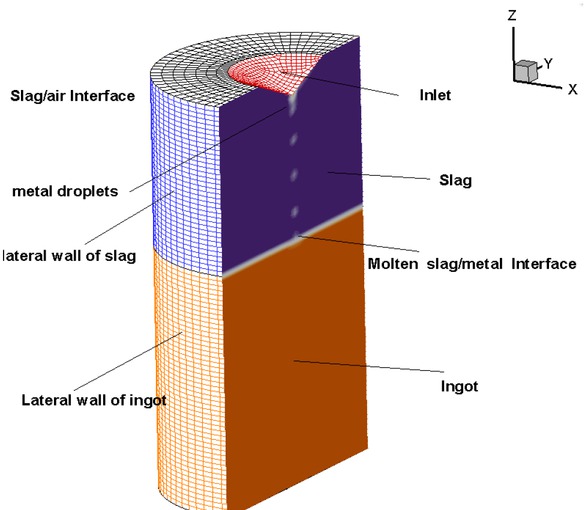
Structure mesh used in the present work
4 Model validation
In order to verify the reliability of mathematical model, the temperature between the plant experiment and numerical simulation has been compared. The plant-scale experiment with a vibration electrode on an ESR furnace has been conducted in Shenyang Research Institute of Foundry. The inner diameter, height, and wall thickness of mold were 220×1000×71 mm. The 4500 A and 50 Hz current was used. The cylindrical electrode was made of Q235 carbon steel, approximately 110mm in diameter. The normal slag composition was 70%wt of calcium fluoride and 30%wt of aluminum oxide. The slag cover thickness was maintained at 120mm during the whole process. The monitor points of slag temperature is measured by a disposable W3Re/W25Re thermocouple. The vibrating electrode containing the laser amplitude sensor was laid out and manufactured following the classic vibration technology. The experimental conditions are as the same as the simulation. Five groups of experiment results are obtained and the averaged value are used. Figure 3 represents the time series of temperature between experiment and simulation. The position of measurement is defined at monitor point as it is convenient for us to arrange the thermocouple during the experiment. The calculation results are in accord with experimental results, hence it is indicated that the mathematical models used in this work are reliable and effective.
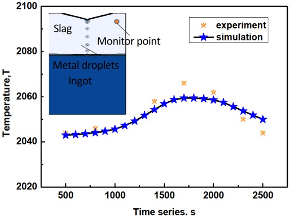
Time series of temperature between experiment and simulation
5 Results and Discussions
Figure 4 presents formation of metal droplets and electromagnetic force distribution under horizontal vibration with flat tip electrode during the whole period (3s). The high electrical resistance of slag provides plenty of energy to melt the electrode tip, leading to the formation of metal droplets. It can be found that the horizontal motion of electrode is transferred to the metal droplets horizontal velocity. The metal droplets flow periodically downward and during this process, they are prone to concentrate in the center of electrode tip, so they become larger and stretched. This is not beneficial to the inclusion removal. The metal droplets in the slag have higher electrical conductance, so the maximum current is located nearby the metal droplets. Hence, the electromagnetic force is distributed intensively around them. Joule heating is determined by the current and electrical resistance of the slag. As the slag resistance is considered constant, the distribution of Joule heating is similar to that of current density.
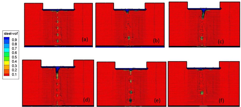
Formation of metal droplets and electromagnetic force distribution under horizontal vibration with flat tip electrode (a) T=0s (b) T=0.5s (c) T=1s (d) T=1.5s (e) T=2.0s (f) T=2.5s
The distribution of temperature under horizontal vibration with flat tip electrode is shown in Figure 5. While the temperature field is related to the Joule heating and boundary conditions, it is also influenced by the dripping metal droplets and fluid flow of molten slag and metal during VE-ESR process. The maximum temperature occurs in the lower slag layer. Its location will vary periodically over time, depending on the vibration frequency and amplitude.
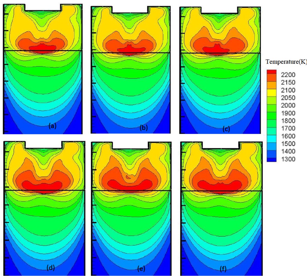
The distribution of temperature under horizontal vibration with flat tip electrode (a) T=0s (b)T=0.5s (c) T=1s (d) T=1.5s (e) T=2.0s (f) T=2.5s
The distribution of droplets and electromagnetic force under horizontal vibration with cone tip electrode are depicted in Figure 6. The same tendency can be observed as in the case with the flat tip electrode. The metal droplets have the uniform periodical behavior and the horizontal velocity. However, the average dimension of the metal droplets is smaller. In addition, larger and stretched metal droplets are not observed. The reason for that behavior lies in the fact that the cone tip electrode accelerates metal droplets towards the center by the gravity force. In the meantime, the horizontal velocity makes them easily separated from the electrode tip. The distributions of temperature under horizontal vibration with cone tip electrode during one period (3s) are shown in Figure 7. Contrary to the flat tip electrode case, temperature fields are periodically distributed, aligned with electrode motion. The maximum temperature zone is located along the slag depth, not in the lower part.
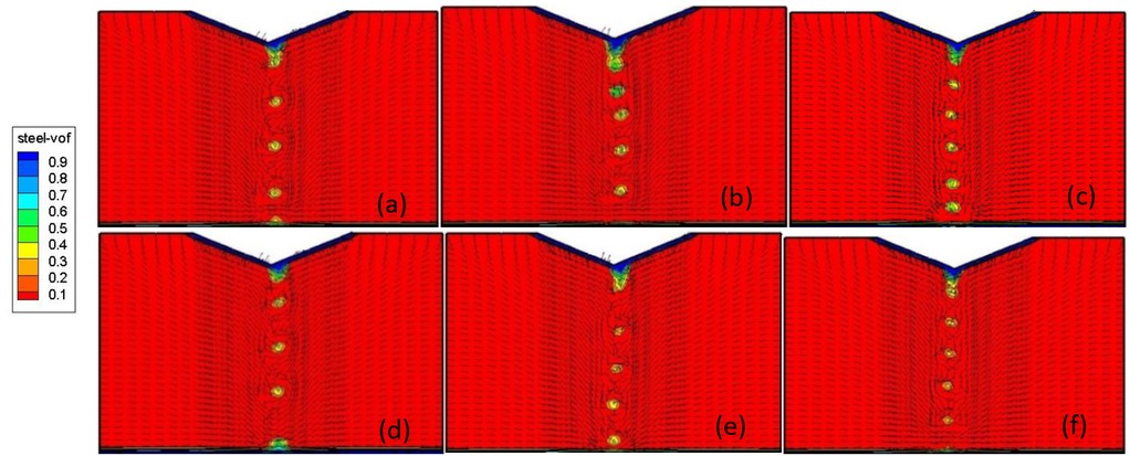
The distribution of droplets and electromagnetic force under horizontal vibration with cone tip electrode (a) T=0s (b) T=0.5s (c) T=1s (d) T=1.5s (e) T=2.0s (f) T=2.5s
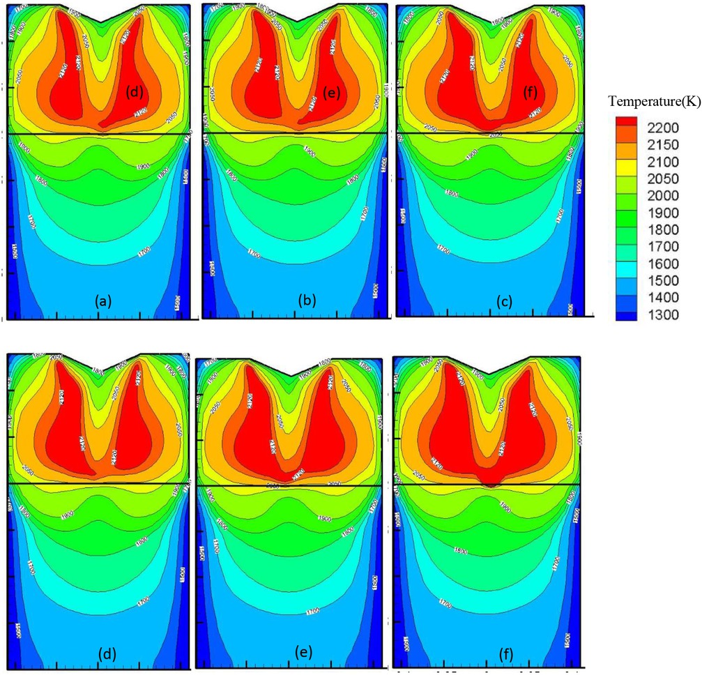
The distribution of temperature under horizontal vibration with cone tip electrode in a whole period (3s) (a) T=0s (b) T=0.5s (c) T=1s (d) T=1.5s (e) T=2.0s (f) T=2.5s
The temperature and velocity distributions in the center line of molten slag under horizontal vibration with different frequency are demonstrated in Figure 8. It can be seen that with the increase in vibration frequency, the maximum temperature decreases. When the frequency changes from 0.17Hz to 1Hz, the maximum temperature reduces from 2050K to 1985K because vibrations can accelerate heat transfer between the slag and mold. Velocity distribution is different from the temperature field; the maximum is located in the center and the minimum at the wall. The metal droplets falling down through the slag layer have larger velocity. Since the electrode vibrates in the horizontal direction, the peak along the center line deviates. When the frequency id increased, the peak value of velocity is decreased from 0.20m/s to 0.125 m/s. Since the metal droplets become smaller, the dripping velocity dominated by the gravity force decreases.
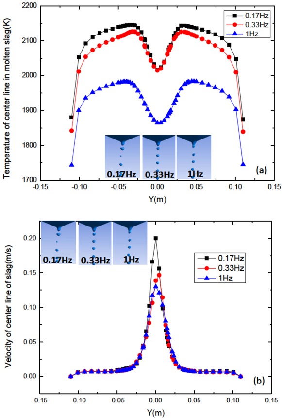
(a) temperature distribution and (b) velocity distribution of the center of molten slag under horizontal vibration with different frequency at 2100s
The temperature distributions and velocity distributions in the center line of molten slag under horizontal vibration with different amplitudes are represented in Figure 9. From the picture, it could be seen that with the increase in vibration amplitude, the maximum temperature in the slag drops. When the vibration amplitude varies from 3mm to 6mm, temperature decreases by 3.9%. The velocity tendency is similar to the case in Figure 8(b). When the vibration amplitude changes from 3 mm to 6 mm, the peak value of velocity rises by 16.7%, from 0.15m/s to 0.175m/s, because electrode vibrations force the flow of nearby molten slag.
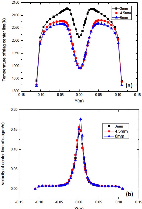
(a) temperature distribution and (b) velocity distribution in the center line of molten slag under horizontal vibration with different amplitude at 2100s
6 Conclusions
A transient full-coupled mathematical model with magneto-hydro-dynamic (MHD) multi-phase approach coupled with a dynamic mesh-based method has been established in the electromagnetic-controlled VE-ESR furnace. The effect of tip profile of electrode on formation of metal droplets and temperature field has been analyzed in the VE-ESR process. The effect of amplitude and frequency of electrode vibration on velocity and temperature field have been discussed.
In the case of the cone tip electrode, the average dimension of metal droplets is smaller compared to the flat tip electrode. In addition, larger and stretched metal droplets are not observed in the case of the cone tip electrode. The temperature field in the cone tip electrode case is distributed periodically, contrary to the flat tip electrode. The maximum temperature zone with the cone tip electrode is located along the z axial in the upper part of slag, not in the lower part. When the frequency changes from 0.17 Hz to 1 Hz, the maximum temperature reduces from 2050K to 1985K and the peak value of velocity decreases from 0.20 m/s to 0.125 m/s. When the vibration amplitude varies from 3 mm to 6 mm, the maximum temperature in the slag cover drops by 3.9% and the peak value of velocity rises by 16.7%.
Acknowledgement
The authors acknowledge Key Program of Joint Funds of the National Natural Science Foundation of China and the Government of Liaoning Province (Grant No.U1508214).
References
[1] Kharicha A., Karimi-Sibaki E., Wu M., Ludwig A., and Bohacek J., Review on Modeling and Simulation of Electroslag Remelting, Steel Res. Int., 2018, 89(1), 1700100.10.1002/srin.201700100Search in Google Scholar
[2] Dub V.S., Levkov L.Ya., Shurygin D.A., Tolstykh D.S. Klochai V. V. Korzun E. L. Garchenko A. A., Electroslag remelting technology for contemporary engineering, retrospection and new possibilities, Metallurgist, 2018, 62(5-6), 511-520.10.1007/s11015-018-0688-9Search in Google Scholar
[3] Detrois M., Jablonski P.D., Hawk, J.A., Evolution of tantalum content during vacuum induction melting and electroslag remelting of a novel martensitic steel, Metall. Mater. Trans. B., 2019, 50(4), 1686-1695.10.1007/s11663-019-01614-zSearch in Google Scholar
[4] Baligidad R.G., Prakash U., Rao V.R., Rao P.K., Ballal N.B., Development of Fe3Al based intermetallic alloys by electroslag remelting, ISIJ Int., 1995, 35(4), 443-445.10.2355/isijinternational.35.443Search in Google Scholar
[5] Wang F., Lou Y.C., Chen R ., Song Z.W., Li B.K., Effect of vibrating electrode on temperature profiles, fluid flow, and pool shape in ESR system based on a comprehensive coupled model, China Foundry, 2015, 12(4), 285-292.Search in Google Scholar
[6] Kharicha A., Wu M., Ludwig A., Simulation of the electric signal during the formation and departure of droplets in the electroslag remelting process, Metall. Mater. Trans. B. 2016, 47, 1427-1434.10.1007/s11663-015-0550-4Search in Google Scholar
[7] Fezi K., Yanke J., Krane M.J.M., Macrosegregation during eectroslag remelting of alloy 625, Metall. Mater. Trans. B. 2015, 46(2), 766-779.10.1007/s11663-014-0254-1Search in Google Scholar
[8] Yu J., Jiang Z., Liu F., Chen K., Li H., Geng X., Effects of metal droplets on electromagnetic field, fluid flow and temperature field in electroslag remelting process, ISIJ Int., 2017,57 (7), 1205-1212.10.2355/isijinternational.ISIJINT-2017-084Search in Google Scholar
[9] Kharicha A., Wu M., Ludwig A., Ramprecht M., Holzgruber H., Influence of frequency of the applied ac current on the electroslag remelting process, Symposium on CFD Modeling and Simulation in Materials Processing held during the TMS Annual Meeting and Exhibition, 2012, 139-146.10.1002/9781118364697.ch17Search in Google Scholar
[10] Kelkar K.M., Patanker S.V., Mitchell A., Computational model of the Electroslag remelting (ESR) process used for the production of ingots of high-performance alloys, Proceedings of the 2005 International Symposium on Liquid Metal Processing and Casting, 2005, 137-144.Search in Google Scholar
[11] Wang Q., Liu Y., Wang F., Li B., Numerical study on the effect of electrode polarity on desulfurization in direct current electroslag remelting process, Metall. Mater. Trans. B.,2017, 48(5): 2649-2663.10.1007/s11663-017-1040-7Search in Google Scholar
[12] Weber V., Jardy A., Dussoubs A., A comprehensive model of the electroslag remelting process: description and validation metal, Mater. Trans. B 2009, 40(3), 271-280.10.1007/s11663-008-9208-9Search in Google Scholar
[13] Jardy A., Ablitzer D., Wadier J. F., Magnetohydrodynamic and thermal behavior of electroslag remelting slags, Metallurgical transactions. B, 1991, 22(1):111-120.10.1007/BF02672532Search in Google Scholar
[14] Kelkar K.M., Patankar S.V., Mitchell A., Computational modeling of electroslag remelting processes, Journal de Physique IV (Proceedings), 2004, 120:421-428.10.1051/jp4:2004120048Search in Google Scholar
[15] Wang Q., Wang R., He Z., Li G., Li B., Li H., Numerical analysis of inclusion motion behavior in electroslag remelting process, Int. J. Heat Mass Transfer., 2018, 125, 1333-1344.10.1016/j.ijheatmasstransfer.2018.04.168Search in Google Scholar
[16] Plotkowski A., Krane M.J.M., The use of inverse heat conduction models for estimation of transient surface heatflux in electroslag remelting, J. Heat Transfer, 2015, 137(3), 031301.10.1115/1.4029038Search in Google Scholar
[17] Dong Y., Hou Z., Jiang Z, Liu H., Study of a single-power two-circuit ESR process with current-carrying mold: mathematical simulation of the process and experimental verification, Metall. Mater. Trans. B., 2018, 49(1), 349-360.10.1007/s11663-017-1140-4Search in Google Scholar
[18] Wang F.,Wang Q., Li B.K.,Comparison of Thermo-electromagneto-hydrodynamic Multiphysical Fields in ESR Furnace with Vibrating and Traditional Electrodes, ISIJ Int. 2017, 57(1) 91-99.10.2355/isijinternational.ISIJINT-2016-436Search in Google Scholar
[19] Wang F., Xiong Y., Li B., Impact of Fill Ratio on Temperature Profile and Metal Bath Configuration in Electroslag Remelting Process With Vibrating Electrode, Steel Res. Int., 2019, 90(4), 1800092.10.1002/srin.201800092Search in Google Scholar
© 2019 F. Wang et al., published by De Gruyter
This work is licensed under the Creative Commons Attribution 4.0 International License.
Articles in the same Issue
- Regular Articles
- Non-equilibrium Phase Transitions in 2D Small-World Networks: Competing Dynamics
- Harmonic waves solution in dual-phase-lag magneto-thermoelasticity
- Multiplicative topological indices of honeycomb derived networks
- Zagreb Polynomials and redefined Zagreb indices of nanostar dendrimers
- Solar concentrators manufacture and automation
- Idea of multi cohesive areas - foundation, current status and perspective
- Derivation method of numerous dynamics in the Special Theory of Relativity
- An application of Nwogu’s Boussinesq model to analyze the head-on collision process between hydroelastic solitary waves
- Competing Risks Model with Partially Step-Stress Accelerate Life Tests in Analyses Lifetime Chen Data under Type-II Censoring Scheme
- Group velocity mismatch at ultrashort electromagnetic pulse propagation in nonlinear metamaterials
- Investigating the impact of dissolved natural gas on the flow characteristics of multicomponent fluid in pipelines
- Analysis of impact load on tubing and shock absorption during perforating
- Energy characteristics of a nonlinear layer at resonant frequencies of wave scattering and generation
- Ion charge separation with new generation of nuclear emulsion films
- On the influence of water on fragmentation of the amino acid L-threonine
- Formulation of heat conduction and thermal conductivity of metals
- Displacement Reliability Analysis of Submerged Multi-body Structure’s Floating Body for Connection Gaps
- Deposits of iron oxides in the human globus pallidus
- Integrability, exact solutions and nonlinear dynamics of a nonisospectral integral-differential system
- Bounds for partition dimension of M-wheels
- Visual Analysis of Cylindrically Polarized Light Beams’ Focal Characteristics by Path Integral
- Analysis of repulsive central universal force field on solar and galactic dynamics
- Solitary Wave Solution of Nonlinear PDEs Arising in Mathematical Physics
- Understanding quantum mechanics: a review and synthesis in precise language
- Plane Wave Reflection in a Compressible Half Space with Initial Stress
- Evaluation of the realism of a full-color reflection H2 analog hologram recorded on ultra-fine-grain silver-halide material
- Graph cutting and its application to biological data
- Time fractional modified KdV-type equations: Lie symmetries, exact solutions and conservation laws
- Exact solutions of equal-width equation and its conservation laws
- MHD and Slip Effect on Two-immiscible Third Grade Fluid on Thin Film Flow over a Vertical Moving Belt
- Vibration Analysis of a Three-Layered FGM Cylindrical Shell Including the Effect Of Ring Support
- Hybrid censoring samples in assessment the lifetime performance index of Chen distributed products
- Study on the law of coal resistivity variation in the process of gas adsorption/desorption
- Mapping of Lineament Structures from Aeromagnetic and Landsat Data Over Ankpa Area of Lower Benue Trough, Nigeria
- Beta Generalized Exponentiated Frechet Distribution with Applications
- INS/gravity gradient aided navigation based on gravitation field particle filter
- Electrodynamics in Euclidean Space Time Geometries
- Dynamics and Wear Analysis of Hydraulic Turbines in Solid-liquid Two-phase Flow
- On Numerical Solution Of The Time Fractional Advection-Diffusion Equation Involving Atangana-Baleanu-Caputo Derivative
- New Complex Solutions to the Nonlinear Electrical Transmission Line Model
- The effects of quantum spectrum of 4 + n-dimensional water around a DNA on pure water in four dimensional universe
- Quantum Phase Estimation Algorithm for Finding Polynomial Roots
- Vibration Equation of Fractional Order Describing Viscoelasticity and Viscous Inertia
- The Errors Recognition and Compensation for the Numerical Control Machine Tools Based on Laser Testing Technology
- Evaluation and Decision Making of Organization Quality Specific Immunity Based on MGDM-IPLAO Method
- Key Frame Extraction of Multi-Resolution Remote Sensing Images Under Quality Constraint
- Influences of Contact Force towards Dressing Contiguous Sense of Linen Clothing
- Modeling and optimization of urban rail transit scheduling with adaptive fruit fly optimization algorithm
- The pseudo-limit problem existing in electromagnetic radiation transmission and its mathematical physics principle analysis
- Chaos synchronization of fractional–order discrete–time systems with different dimensions using two scaling matrices
- Stress Characteristics and Overload Failure Analysis of Cemented Sand and Gravel Dam in Naheng Reservoir
- A Big Data Analysis Method Based on Modified Collaborative Filtering Recommendation Algorithms
- Semi-supervised Classification Based Mixed Sampling for Imbalanced Data
- The Influence of Trading Volume, Market Trend, and Monetary Policy on Characteristics of the Chinese Stock Exchange: An Econophysics Perspective
- Estimation of sand water content using GPR combined time-frequency analysis in the Ordos Basin, China
- Special Issue Applications of Nonlinear Dynamics
- Discrete approximate iterative method for fuzzy investment portfolio based on transaction cost threshold constraint
- Multi-objective performance optimization of ORC cycle based on improved ant colony algorithm
- Information retrieval algorithm of industrial cluster based on vector space
- Parametric model updating with frequency and MAC combined objective function of port crane structure based on operational modal analysis
- Evacuation simulation of different flow ratios in low-density state
- A pointer location algorithm for computer visionbased automatic reading recognition of pointer gauges
- A cloud computing separation model based on information flow
- Optimizing model and algorithm for railway freight loading problem
- Denoising data acquisition algorithm for array pixelated CdZnTe nuclear detector
- Radiation effects of nuclear physics rays on hepatoma cells
- Special issue: XXVth Symposium on Electromagnetic Phenomena in Nonlinear Circuits (EPNC2018)
- A study on numerical integration methods for rendering atmospheric scattering phenomenon
- Wave propagation time optimization for geodesic distances calculation using the Heat Method
- Analysis of electricity generation efficiency in photovoltaic building systems made of HIT-IBC cells for multi-family residential buildings
- A structural quality evaluation model for three-dimensional simulations
- WiFi Electromagnetic Field Modelling for Indoor Localization
- Modeling Human Pupil Dilation to Decouple the Pupillary Light Reflex
- Principal Component Analysis based on data characteristics for dimensionality reduction of ECG recordings in arrhythmia classification
- Blinking Extraction in Eye gaze System for Stereoscopy Movies
- Optimization of screen-space directional occlusion algorithms
- Heuristic based real-time hybrid rendering with the use of rasterization and ray tracing method
- Review of muscle modelling methods from the point of view of motion biomechanics with particular emphasis on the shoulder
- The use of segmented-shifted grain-oriented sheets in magnetic circuits of small AC motors
- High Temperature Permanent Magnet Synchronous Machine Analysis of Thermal Field
- Inverse approach for concentrated winding surface permanent magnet synchronous machines noiseless design
- An enameled wire with a semi-conductive layer: A solution for a better distibution of the voltage stresses in motor windings
- High temperature machines: topologies and preliminary design
- Aging monitoring of electrical machines using winding high frequency equivalent circuits
- Design of inorganic coils for high temperature electrical machines
- A New Concept for Deeper Integration of Converters and Drives in Electrical Machines: Simulation and Experimental Investigations
- Special Issue on Energetic Materials and Processes
- Investigations into the mechanisms of electrohydrodynamic instability in free surface electrospinning
- Effect of Pressure Distribution on the Energy Dissipation of Lap Joints under Equal Pre-tension Force
- Research on microstructure and forming mechanism of TiC/1Cr12Ni3Mo2V composite based on laser solid forming
- Crystallization of Nano-TiO2 Films based on Glass Fiber Fabric Substrate and Its Impact on Catalytic Performance
- Effect of Adding Rare Earth Elements Er and Gd on the Corrosion Residual Strength of Magnesium Alloy
- Closed-die Forging Technology and Numerical Simulation of Aluminum Alloy Connecting Rod
- Numerical Simulation and Experimental Research on Material Parameters Solution and Shape Control of Sandwich Panels with Aluminum Honeycomb
- Research and Analysis of the Effect of Heat Treatment on Damping Properties of Ductile Iron
- Effect of austenitising heat treatment on microstructure and properties of a nitrogen bearing martensitic stainless steel
- Special Issue on Fundamental Physics of Thermal Transports and Energy Conversions
- Numerical simulation of welding distortions in large structures with a simplified engineering approach
- Investigation on the effect of electrode tip on formation of metal droplets and temperature profile in a vibrating electrode electroslag remelting process
- Effect of North Wall Materials on the Thermal Environment in Chinese Solar Greenhouse (Part A: Experimental Researches)
- Three-dimensional optimal design of a cooled turbine considering the coolant-requirement change
- Theoretical analysis of particle size re-distribution due to Ostwald ripening in the fuel cell catalyst layer
- Effect of phase change materials on heat dissipation of a multiple heat source system
- Wetting properties and performance of modified composite collectors in a membrane-based wet electrostatic precipitator
- Implementation of the Semi Empirical Kinetic Soot Model Within Chemistry Tabulation Framework for Efficient Emissions Predictions in Diesel Engines
- Comparison and analyses of two thermal performance evaluation models for a public building
- A Novel Evaluation Method For Particle Deposition Measurement
- Effect of the two-phase hybrid mode of effervescent atomizer on the atomization characteristics
- Erratum
- Integrability analysis of the partial differential equation describing the classical bond-pricing model of mathematical finance
- Erratum to: Energy converting layers for thin-film flexible photovoltaic structures