Heuristic based real-time hybrid rendering with the use of rasterization and ray tracing method
-
Patryk Walewski


Abstract
Nowadays, rasterization is the most common method used to achieve real-time semi-photorealistic effects in games or interactive applications. Some of those effects are not easily achievable, thus require more complicated methods and are difficult to obtain. The appearance of the presented worlds depends to a large extent on the approximation to the physical basis of light behaviour in them. The best effects in this regard are global illumination algorithms. Each of them including ray tracing give the most plausible effects, but at cost of higher computational complexity. Today’s hardware allows usage of ray tracing methods in-real time on Graphics Processing Units (GPU) thanks to its parallel nature. However, using ray tracing as a single rendering method may still result in poor performance, especially when used to create many image effects in complex environments. In this paper we present a hybrid approach for real-time rendering using both rasterization and ray tracing using heuristic, which determines whether to render secondary effects such as shadows, reflections and refractions for individual objects considering their relevancy and cost of rendering those effects for these objects in particular case.
1 Introduction
Computer graphics is an area of study, which tries to achieve best effects of generating the most realistic images of artificial environment while keeping the best performance. There were several rendering methods developed over the years, which were then optimized in order to achieve better-looking results and to speed them up. The aim was to get the performance that allows to use the method in real-time applications with additional requirement of possibility of full interaction. It means that the resulting performance should allow application to render single frame in less than 33ms (at least 30 frames per second (FPS)). The first rendering method that was widely used in generating images in real-time was rendering using rasterization thanks to its speed and wide support of the GPU. It was widely used in computer games and 3D interactive applications within many years. Further studies allowed to use it not only in computer graphics, but also in scientific or database field [1]. The method which was the result of trying to achieve more photorealistic results in rendering images was ray tracing. Its nature allowed to obtain better looking results but at cost of higher computational complexity. The main reason of highly demanded computational task is that many rays may be generated in order to calculate exact color of specific pixel, and each ray must be determined whether and which objects does it intersects. Further rendering methods that were developed, allowed to obtain more effects, such as global illumination, which allows objects to receive lightning not only directly from light sources, but also from other objects in the scene, but they were applied mainly in offline rendering applications that may better simulate the way how light interacts with objects, due to the time-demanding computations. Further development of GPUs whichwere dedicated for images computations allowed researchers to optimize those methods and allowed developing improved algorithms that achieved better results at a better time, that has started to reach real-time demands. Performance increase caused by technology development allowed ray tracing to be used as a rendering method on GPU due to its parallel nature [2]. Because the basic ray
tracing method is able to be paralleled [3], the usage of GPU as parallel processor makes a promising way in producing real-time, interactive solutions using ray tracing. The first work that introduced the possibility of real-time ray tracing use was Nvidia Ray Tracing Demo developed using CUDA programming platform [4]. With further development, a special GPU-based ray tracing engine was developed by Nvidia engineers called Nvidia OptiX [5]. It is a professional framework and is being used in many professional graphic applications, including Adobe After Effects or Pixar’s lighting preview tool. Another method of global illumination, which currently allows for a real-time approach, where the camera could be easily navigated by a user [6] is for example photon mapping [7].
In this paper, we present and describe a hybrid approach to rendering that combines all presented methods. It uses rasterization as the first rendering stage that calculates basic lighting, using deferred rendering [8] method, which allows to postpone shading process to point after filling structure called G-Buffer with visible scene data. After deferred rendering, in the next stage, a heuristic is carried out on CPU in order to calculate and select the most suitable objects to render secondary effects for. The result of heuristic is then passed to GPU, and in the third stage ray tracing is used to calculate shadows, reflections and refractions for appropriate objects. Thanks to this approach, we can ensure that basic image will always be available in real-time, and our heuristic will evaluate, if there is still enough time to render effects using ray tracing and will try to maintain real-time characteristic of rendering.
The way the heuristic will perform selective rendering and try to select which objects should have secondary effects rendered is based on human perception – the way our eyes perceives specific elements. It depends on both current arrangement of objects in scene and the way user currently interacts with viewed image and is called visual attention [9]. It may differ even when user have specific task to do inside virtual environment [10], or depending on how dynamically the image is changing [11].
The organization of this paper is following: after the introduction, a related work regarding ray tracing optimization as well as hybrid rendering solutions is presented. Then we present our hybrid rendering solution including details of different performed stages and applied algorithms. In the next section we present performed tests, following by received results in next section. Last section consist of conclusions from results, future work proposals and brief summary.
2 Related work
The initial work introducing full recursive ray tracing idea was proposed in [12] by Turner Whitted (Figure 1). In this algorithm, primary rays were responsible for geometry detection and base surface color calculations, where the secondary rays were responsible for additional effects – reflections, refractions and shadows. Despite parallel characteristic of ray tracing, it is still more computationally expensive than standard rendering pipeline and one of proposals of speeding it up was usage of space partitioning algorithms, like k-d trees [13]. Furthermore, there were researches to efficiently combine both methods – speed of rasterization and ease of obtaining better effects from ray tracing method. Thanks to this, hybrid rendering methods were developed and those methods can be divided into three groups. The first group tries to split rendering workload into both GPU and Central Processing Unit. An example can be paper [14], where rendering process is divided into three GPU passes and two CPU passes, where the results of the second pass done in GPU is received by CPU where reflection and refraction pass using ray tracing may be performed. Work [15] is similar except that it uses DirectX 11 and HLSL instead of OpenGL and GLSL. Paper [16] describes usage of rasterization in order to generate visible geometry and passing data to CPU in order to process ray tracing stage. The second group consists of methods that uses ray tracing to generate only effects hardly achievable in rasterization. For example, in [17] kd trees were used to accelerate ray tracing calculations for shadows generation. Last group are methods that uses selective rendering that rejects some effects for part of the image basing on human perception [18, 19].
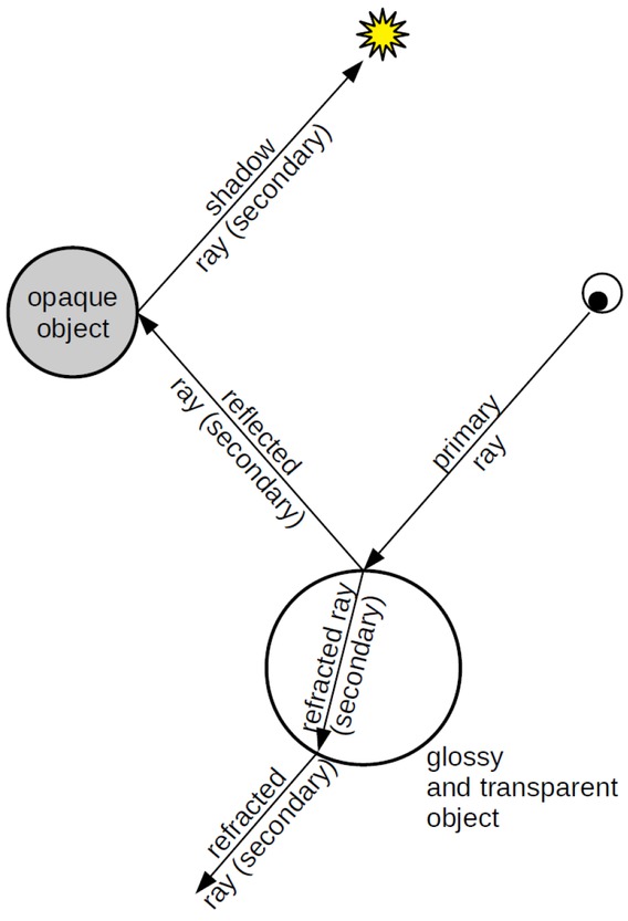
Whitted’s idea of the ray-tracing algorithm
There are several works that have been further investigating an area of hybrid rendering. Each work focused on different aspect of rendering, trying to increase visual level of rendered images, implementing more visual effects or reducing computing time while maintaining the same quality. There are several approaches for hybrid rendering that can be highlighted.
2.1 Offline hybrid rendering using light transport methods
Reference [20] is a very popular article frequently cited among others. It connects rasterization and ray tracing method and additionally implements some additional graphic algorithms, like ambient occlusion, and extends basic ray tracing method. Authors proposed usage of k-d trees and voxels (points lying on regular 3D grid) to optimize scene calculations. However, this solution is not efficient enough to be a real-time renderer, giving results in more than a second. Another problem is the fact that huge and complicated scenes cause performance drop as well as great memory demand in order to maintain all required scene structures.
2.2 Hybrid rendering of shadows and reflections
A series of articles [21, 22, 23, 24] presents another approach to the hybrid rendering issue. This solution is integrated into authors’ own game engine prototype, which is successively extended with new visual effects. The first implemented effect included dynamic shadows, which turned out to be faster than ray tracing solution but at cost of high memory demand. Next added effect was dynamic reflection of environment which was a hybrid solution of ray tracing and Screen Space Reflection (SSR). If a reflection could not be calculated by SSR, the ray tracing method was used. Those reflections were additionally filtered with Gaussian blur in order to reduce visible graphical artifacts. They also prepared a comparison of different structure data provided by ray tracing API Nvidia OptiX [25] where the structure must have been suitable to handle dynamically deforming objects. The problematic scenario were scenes with multiple recursive reflections (like e.g. mirrors facing each-other).
2.3 Hybrid rendering with heuristic approach
This series of publications by Sabino T. L. R. et al. [26, 27, 28, 29, 30, 31, 32] presents development of authorial hybrid renderer called PHRT. The first stage uses rasterization with deferred rendering method which fills G-Buffer with appropriated data. Then, the data from G-Buffer is used in the stage of calculating secondary effects which allows to replace the first stage of ray tracing where the primary rays are intersecting the objects in the scene. Additionally, a heuristic was introduced to adaptively select appropriate objects which will receive secondary effects in order to maintain real-time characteristic. The solution was then adopted as a simple game engine demo, and the heuristic was optimized in order to calculate and manage objects that will receive reflections. The tests they performed confirmed that proposed heuristic satisfies set conditions and can be still developed further.
2.4 Voxel based selective rendering
Two another publications [33, 34] presented a way of implementing hybrid rendering based on voxels grid which are used to optimize rendering process. An analysis is carried on how such structures affects memory demand and a structure called A-Buffer is being used. This structure allows the mix of colors from specific triangle fragments onto another pixel. The effort is to reduce the memory cost of maintaining those structures, and a screen space object complexity cost is being measured. The result for scenes of low complexity fits real-time demands, but the more extended the scene is, the more time it takes to build a structure.
2.5 Mobile GPU hybrid rendering
There are also researches to optimally perform hybrid rendering on mobile devices. Article [35] provides proposal of special architecture for rasterization and ray tracing rendering in use of mobile GPU. As a result they achieve not only increased performance in terms of rendering speed, but also achieved lower energy consumption compared with ray tracing only solution. They will continue the analysis of architectures and they predict to see further energy consumption decrease.
2.6 Ray tracing with DirectX Ray Tracing and NVIDIA RTX
Recently, a two promising APIs were announced and released that provide support for implementing GPUray tracing algorithms. Those are DirectX Ray Tracing API (DXR) and NVIDIA RTX API. The second one will be additionally beneficial on NVIDIA GPU’s based on Volta and future microarchitectures, which is currently totally new one. Because these were recently announced, besides many promoting materials and presentations, there is currently a paper describing results of implementing a ray tracing method, for adaptive temporal antialiasing along with rasterization [36]. It states, that both API allowed to easily overcome technical difficulties in combining both rendering techniques and ray tracing ecosystem will adopt along with further versions of GPUs and drivers over the next years.
3 GPU heuristic based hybrid rendering
Our application allows rendering scenes using hybrid rendering, in which four stages can be distinguished. The first stage is a rasterization stage, where G-Buffer is filled with data and then base scene lighting is calculated and stored in P-Buffer. The second stage is heuristic stage, where all visible scene objects are reinvestigated for relevancy and cost parameters and result of this stage is being passed to the next one which is ray tracing stage. In this stage all objects that have been selected by heuristic are ray traced in order to generate secondary effects. Results of the first and the third stage are then merged into one – final result during the fourth stage – blending stage.
Application allows creating either one of basic primitives – plane, cube or sphere with specified number of slices and stacks or reading model from file. Each object can be placed at any point in the world, specifying its position, rotation in Euler angles and scale. Each object may have assigned any user – specified material, one material can be shared by many objects. Each material may have defined both texture and basic color for specific properties, which are listed in Table 1.
Available material properties
| Material property | Colors components meaning |
|---|---|
| Emission | RGB – emission color values |
| Ambient | RGB – ambient color values |
| Diffuse | RGB – diffuse color values, A – opacity |
| Specular | RGB – specular color values, A – specular exponent valuea |
| Normal map | RGB – normal direction in tangent space |
| Optical properties | R– reflectivity, G– index of refrection, B– opacity |
aValue of 0.0 means exponent equal to 1, Value of 1.0 means exponent equal to 255.0, values between are linearly interpolated
Additional material properties are texture tiling, texture offset, and shadow casting boolean value. Each scene can have up to 8 directional lights, up to 32 point lights, and up to 32 spot lights. Image can be rendered from either perspective or orthographic camera, and additional scene parameters are global ambient color, environment refraction index and skybox map, which can be created using six skybox textures, each for different side [37]. Scene objects, materials and parameters can be read from specially formatted text files. One of implemented improvements is gamma correction, which makes lighting calculation more physically-correct.
3.1 The first stage – rasterization
In this stage, scene is being rendered using rasterization with deferred rendering method. Thanks to this, lighting computation can be performed only after all geometry has been tested for visibility. The pseudo-code of this stage and used shaders code is presented in listings 1 – 5. Note that the comments in the codes are marked with a small triangle (ᐅ).
Rasterization stage frame rendering function
Enable depth test
Clear depth buffer
Enable G-Buffer attatch its textures for writing
Clear depth buffer
for each loaded shader do
Update current camera view Projection matrix
end for
for each model in scene do
if world matrix is dirty then
Update world and normal matrix
end if
for each mesh in model do
Use shader associated with appriopriate model’s
material
Update shader’s world and normal matrix
Bind approppriate textures from material
Update shader values with values from material
Draw mesh ᐅ fill gBuffer with mesh data, listing
2 and 3
end for
end for
Draw skybox cube
Disable depth test
Disable G-Buffer
Enable P-Buffer and attatch its texture for writing
Use deferred shading shader
Bind approppriate G-Buffer textures
Update camera position value
ᐅ produce image with
lighting calculations
Draw screen quad
ᐅ listing 4 and 5
Unbind textures
Disable P-Buffer
Rasterization stage G-Buffer fill vertex shader
input: position p, normal n, tangent t, bitangent b, texture coordinates itc
output: tbn matrix tbn, world position wp, texture coordinates otc
uniforms: world matrix wm, viewProjection matrix vpm, normal matrix nm, texture tiling tt, texture offset toff
tbn←mat3(norm(nm * t), norm(nm * b), norm(nm * n)) wp←wm * p
otc←toff + (itc * tt)
gl_Position←vpm * wm * vec4(p, 1.0)
Rasterization stage G-Buffer fill fragment shader
input: tbn matrix tbn, world position wp, texture coordinates itc
output: position op, normal on, emission oe, ambient oa, diffuse od, specular os, optical properties oop ▹ G-Buffer textures
uniforms: emission ie, ambient ia, diffuse id, specular is, shniness iss, optical properties iop
samplers: emission texture et, ambient texture at, diffuse texture dt, specular texture st, normal texture nt, optical properties texture opt
op←vec4(wp, 1.0)
on ← vec4((norm(tbn*norm(tex(nt, itc).rgb*2.0-
1.0))+1.0)*0.5, 0.0)
oe←tex(et, itc) * ie in linear space
oa←tex(at, itc) * ia in linear space
od←tex(dt, itc) * id in linear space
os←vec4(tex(st, itc) * is * is.a, tex(st, itc).a * iss) in linear space
oop←tex(opt, itc) * iop
Rasterization stage deferred shading vertex shader
input: position p, texture coordinates itc
output: texture coordinates otc
otc←itc
gl_Position←vec4(p, 1.0)
Rasterization stage deferred shading fragment shader
input: texture coordinates itc
output: fragment color ofc
uniforms: number of directional lights, number of point lights, number of spot lights, environment ambient color, view position, directional lights array, point lights array, spot lights array
samplers: position texture, normal texture, emission texture, ambient texture, diffuse texture, specular texture
ᐅ G-Buffer
textures
Retrieve the data from G-Buffer using itc
ᐅ lighting calculations using Blinn-Phong reflection model:
color gets emission + environment_ambient_color * ambient_texture
for each directional light do
Add lighting calculated for this directional light to
color
end for
for each point light do
Add lighting calculated for this point light to color
end for
for each spot light do
Add lighting calculated for this spot light to color
end for
ofc gets vec4(light.rgb, 1.0)
This stage was implemented using OpenGL and GLSL. To perform calculations based on objects’ materials, deferred rendering fills G-Buffer structure with appropriate data, which is then used in the lighting calculation pass and next stages. Thanks to technique called Multiple Render Targets (MRT), we can use multiple textures, which will contain information provided by deferred rendering. Every application can define its own values saved in G-buffer. In our case, we defined 8 textures for material parameters, one texture for z-buffer and one texture for lighting calculation in final image. As for z-buffer, a reversed z-mapping algorithm was implemented [38], which allows for better depth buffer precision. This makes the depth texture look opposite to what default depth buffer produces – objects that are close to observer appears brighter than those that are further away. Per-pixel data that is stored in G-Buffer contains: position, normal, emission color, ambient color, diffuse color, specular color, optical properties, heuristic mask, depth buffer. Details and formats of all targets and data stored in G-Buffer can be seen in Table 2. This stored data can be used by ray tracing stage to calculate appropriate visual effects depending on optical properties of specific pixel, and heuristic mask which is being filled during heuristic stage. This allows to avoid ray tracing stage of primary rays intersection which would determine objects that would have been hit by camera rays.
G-buffer render targets
| Target type | Target formatb | Notes |
|---|---|---|
| Position | GL_RGBA32F | - |
| Normal | GL_RGBA16 | 8 bit per component variant had too low precision |
| Emission | GL_RGBA8 | - |
| Ambient | GL_RGBA8 | - |
| Diffuse | GL_RGBA8 | - |
| Specular | GL_RGBA8 | - |
| Optical | GL_RGBA8 | Color channels |
| properties | ||
| coresponding to same properties as for texture | ||
| Heuristic | GL_R32F | Floating point |
| mask | ||
| type to enable texture visualization | ||
| Depth | GL_DEPTH_- | 32-bit float due to |
| buffer | ||
| COMPONENT32F | reversed z-buffer implementation |
bFormat of texture specified to OpenGL
An example of textures generated in this stage for example scene is shown in Figure 2.
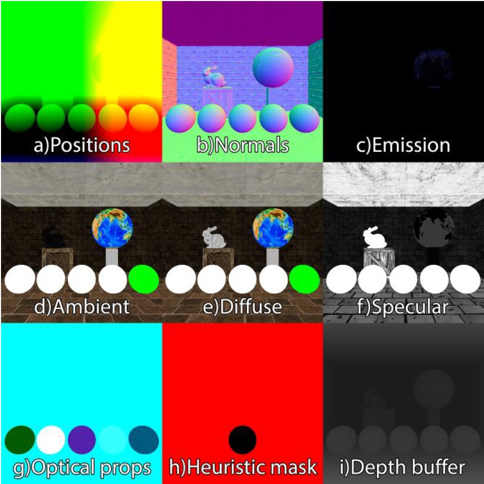
An example of data generated in G-Bufer: a) Position, b) normal, c) emission color, d) ambient color, e) diffuse color, f) specular color, g) optical properties, h) heuristic mask, i) depth buffer
Color textures appears darker than they are due to gamma correction implementation, and because textures are already in sRGB space, they have to be transformed to linear space before any calculations. As for position and normal textures, they save fragment positions and normals in world space coordinates. Normal coordinates values are mapped from [−1, 1] to [0, 1] to be in texture values range. As it was mentioned earlier, heuristic mask is calculated in heuristic stage, but it is included in G-Buffer because heuristic uses depth buffer generated in the first stage in order to calculate object’s visible part for its coefficient calculations. The result of lighting calculations pass that uses data generated during previous pass is stored in P-buffer structure, which, in our case, consists of only one texture of GL_RGBA16F type. The result of this pass is presented in Figure 3.
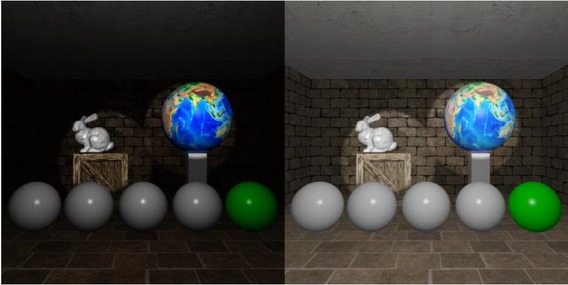
Example of lighting calculations final image. On the left is original image texture stored in P-Buffer, on the right is the same image with gamma correction applied
The lighting is calculated using Blinn-Phong reflection model. In this scene there was one point light positioned above camera, and two spot lights, one directed on Stanford bunny model, and the second lighting earth sphere.
Such prepared data is sufficient to perform stage with ray tracing method, in which primary rays that would determine geometry hit can be replaced with data accumulated in G-Buffer, and all secondary effects that will be calculated using this stage can be blended into lighting stage image. However, before we start ray tracing stage, a heuristic has to be carried out in order to select only those objects, which will fit provided time constraints.
3.2 The second stage – heuristic
Heuristic we propose is somehow similar to the one presented by Sabino et al. It was incorporated in order to maintain real-time characteristic of application by omitting generation of some secondary effects if there is no time left for calculating them. Listing 6 contains pseudo-code for heuristic calculations.
Heuristic stage calculations – update function
Enable G-Buffer and attatch heuristic texture for writing
Enable depth test
depth test←GL_GEQUAL
Use heuristic shader
lights_count←number of lights
for each object in scene do
Update shader’s worldViewProjection matrix
Start OpenGL query for passed samples calculation
Draw object
A←query result
if query result is zero then
Mark object as not selected in this frame Process next object
end if
Calculate bounding box center in NDC (bb) space using matrices
P←(max(1.0-sqrt(bb.x*bb.x+bb.y*bb.y),0.0)
*0.99)+0.01
D←distance between bounding box in and view position
Q←lights_count
if object is reflective then
Q←Q + 1 + lights_count
end if
if object is refractive then
Q←Q + 4 + lights_count
end if
object_cost←A * Q * object.estimatedCost ᐅ eq. (2)
object_relevancy ← (object.wasSelected * previous-
SelectionImportance + V) * object.heuristicRelevance ᐅ eq. (3)
end for
Sort selected objects by cost
Add pointers for selected objects to more relevant selected objects
Clear heuristic mask texture
costLeftForRT←defined cost left for RT
while costLeftForRT > 0 and visible_objects > 0 do
Set obj_cur←selected object with the highest cost
if obj_cur.cost > costLeftForRT then
Mark obj_cur as not selected in this frame
Remove obj_cur from selected objects container
else if obj_cur points to more relevant object then
obj_cur←more relevant object
Update shader’s worldViewProjection matrix Draw obj_cur
costLeftForRT←costLeftForRT - obj_cur.cost
Mark obj_cur as selected in this frame
Remove obj_cur from selected objects container
else
Update shader’s worldViewProjection matrix
Draw obj_cur
costLeftForRT←costLeftForRT - obj_cur.cost
Mark obj_cur as selected in this frame
Remove obj_cur from selected objects container
end if
end while
Draw skybox cube
Disable depth test
Disable G_Buffer
We do not provide pseudo-code for heuristic’s shaders as they only have to fill heuristic’s texture with solid color for object’s pixels and thus are trivial. Heuristic’s task is not only to constraint ray tracing effects generation, but also to do it the way, that those objects that are most relevant to visual appearance and contribute the most for human visual perception will be selected for ray tracing instead of those with less importance. The heuristic itself could not predict correctly if some given object is important from the environment designer point of view, so it has additionally some factors that can be adjusted during scene creation. As for automatic calculation of objects relevancy there were two reasons on how to configure such behavior, both coming from the way human perception works. The first one is assumption that objects that are closer to the center of visible area and closer to the observer are more important than those further away. This comes from the fact that we unconsciously ignore many visual effects while image we see is frequently changing. The second one could be the fact that our perception is highly changed when given some kind of motivation, like e.g. task of looking for something in specific environment or focusing in other aspects rather than image only. Although this can approximate to some extent the way we will perceive the image and partially relieve designers from changing the environment to meet performance restrictions, they still may, and should, assign some factors that will indicate that some particular objects are more important than others. A short description of this behavior would be that “for visible objects in the scene, selectX most relevant from the perception point of view that will meet time constraint T”.
This heuristic consists of three phases. One phase is offline phase – its the part of assigning heuristic values by user during scene design, and two another phases are phases which happen every frame between rasterization stage and ray tracing stage. The heuristic itself consists of both values that can be set by environment designers and of values that are calculated based on current scene visibility. During every-frame phases, a graph of scene objects is created, and then is used to determine which objects should have secondary effects in specified time constraints generated during ray tracing phase.
As for offline phase, there are four user-defined values – two for heuristic in general and two per every object. First value that can be specified for heuristic is time available in ray tracing phase (T). This is value that will be set as initial ray tracing stage time every frame, and tested against all objects costs. It mainly depends on available computing power of running machine, which allows to adopt it depending on whole application performance. The second general value is the importance of selecting previously selected objects (I). This value allows to introduce some stability in generated image, so if any object has been selected for ray tracing stage, it will be more important to select it in the next frame because frequent changes in object visible visual effects will be highly noticeable, and by setting this parameter to high value, these changes can be reduced. Another factor is one of factors assigned per-object. It is object static relevancy (K), which determines how important is to render secondary effects for this particular object. High values means that this object’s relevancy may be higher than for objects that are more relevant from the perception point of view than this one. The last factor configured by user is estimated object’s cost (E). This value allows to indicate heuristic, that object may be more computationally complex for ray tracing stage due to e.g. its complicated shape, unnatural size, or to adjust performance for this object, if it causes heavy performance drop for designed scene form. All those four factors are used in calculations that are performed during the second and the third phase.
The second phase, which is already performed every frame is the one in which each object current relevancy and current processing cost. Firstly, size of object visible area (A) is calculated. It is exactly the number of visible pixels that this object covers. It is measured using depth buffer generated in rasterization stage and OpenGL queries. If there is no such pixel, this means that the object is not visible and is being rejected. Next calculated value is distance of object 2D projection center from the view plane center (P). It is calculated using center of 3D bounding box that is transformed using world, view and projection matrices. This value is in range [0.01, 1.0], where 0.01 means that the center is out of the view plane, and 1.0 means center of object exactly in center of the view plane. The third value that is used for visibility calculations is distance from the object to the observer (camera) in 3D space (D). Using these three values, we can calculate object’s visibility (V) using the following equation.
Object’s visibility will affect the value of relevancy for analyzed object. Next step is to calculate estimated numbers of required rays to calculate all visual effects for particular object (Q). This is initially a number of lights in scene, which is then increased by number of lights + 1, if object is reflective, and by number of lights + 4 if object is refractive. Every object has additionally a Boolean value that indicateswhether this object has been selected or not for secondary effects rendering in previous frame (S). Using all calculated values, we can finally calculate object’s current processing cost (C) and relevancy (R) using the following equations.
With these calculated values we can add node to the graph for this object, which contains reference to object, its calculated cost and relevancy. Table 3 presents all factors that are used by heuristic during every object estimated cost and relevancy calculations.
Heuristic factors
| Factor letter | Description | Heuristic variable/User defined |
|---|---|---|
| T | Time available for ray tracing stage – global | User defined |
| I | Importance of selecting previosly selected objects – global | User defined |
| K | Object static relevancy | User defined |
| E | Estimated objec’s cost | User defined |
| A | Size of object’s visible area | Heuristic variable |
| P | Distance between object’s projection and center of viev plane | Heuristic variable |
| D | Distance between object and observer | Heuristic variable |
| V | Object’s visibility | Heuristic variable |
| Q | Estimated number of required rays | Heuristic variable |
| S | Flag of object being selected in previous frame | Heuristic variable |
| C | Object’s current processing cost | Heuristic variable |
| R | Object’s current relevancy | Heuristic variable |
After all objects have been updated, the graph is sorted by objects calculated processing cost in descending order, so every node points to a node with object, which cost is smaller or equal to this one. Additionally, all nodes points to nodes that have objects with cost smaller or equal, but having higher relevancy – these pointer are sorted by relevancy in descending order. This is the end of the second phase.
The third phase is this one in which heuristic makes decision which objects will receive secondary effects generation. Heuristic mask is cleared by setting mask texture value to 0.0 and current cost left for ray tracing is set to value that was provided by user, and while there is still cost left for ray tracing, we check if object cost is less than this available time. If not, the object is set as not selected by heuristic and is removed from the graph. If there is time to render this object, heuristic checks if there are any object that are more relevant to render (if node points to another node with equal or less cost and greater relevancy). If it does, this object with higher relevancy (if there are multiple, the one with the highest) is selected as the one receiving secondary effects. The object is being rendered to heuristic mask – and marking pixels which belongs to this object with color, and current available cost is decreased by this object’s cost. If there were no more relevant objects, this one is being processed similarly. Selected objects are marked as selected by heuristic and are removed from current selection graph. If we run out of available cost, all remaining objects are set as not selected and moved to the graph for next frame. After this phase, heuristic is done and heuristic mask texture is ready to be passed to ray tracing stage, which could be seen in Figure 2 – red color means pixel that will be ray traced while black one are pixels that will be ignored.
Let’s make an example. Let the left time available for ray tracing be 400. Figure 4 presents an example of a graph that could be created by heuristic.
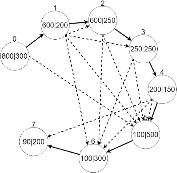
An example of nodes of heuristic’s graph. Value above node is its index. Value to the left of vertical bar is object’s current cost, value to the right is object’s relevancy
Every node points to node with processing cost not greater than this one. Additionally, every node points to nodes with cost not greater and higher relevancy. As for now, the first node that has cost smaller than available time is the node with index 3, so all nodes with smaller indices are removed from the graph. This node points to node 4 as next in cost order, and nodes 5 and 6 as nodes with higher relevancy. From nodes 5 and 6, node 5 has higher relevancy, so this node is selected for processing, after which it is removed from the graph. Operation is performed as long as there is still available time for rendering and the graph is not empty.
3.3 The third stage – ray tracing
In this stage, ray tracing method is responsible for generating secondary effects for objects that have been selected basing on heuristic decisions. Those effects includes shadows, reflections and refractions. It was implemented using NVIDIA OptiX, and CUDA language for algorithms. It means that there is one part of code that runs on host – which in CUDA refers to processor and its memory, and the other runs on device –which refers to GPU and its memory. Multiple parallel functions running on GPU are called kernels. Listing 7 presents frame rendering pseudo-code running on host while listings 8a-d present so called OptiX’s programs running on GPU.
Ray tracing stage frame rendering function
Update context’s view position value
Launch 2D ray tracing ray generation program with width and height
Enable ray tracing results buffer
Attach shadows texture for writing
Draw shadows texture using shadows buffer
Attach reflections texture for writing
Draw reflections texture using shadows buffer
Attach refractions texture for writing
Draw refractions texture using shadows buffer
Disable ray tracing results buffer
Ray tracing stage CUDA rendering pipeline – generate secondary rays
ᐅ this function wil be run on multiple kernels upon launch call
function RT_PROGRAM
generate_secondary_rays()
input: launch index li
output: shadows buffer sb, reflections buffer reflb, refractions buffer refrb ᐅ G-Buffer textures
samplers: position texture, normal texture, emission texture, ambient texture, diffuse texture, specular texture, optical properties texture, heuristic mask texture
tc ←li / buffer.size
if heuristic mask sample is zero then
sb[li]←0
reflb[li]←0
refrb[li]←0
return
end if
if normal sample saved in texture is of zero length then
sb[li]←0
reflb[li]←skybox sample value in linear space
refrb[li]←0
return
end if
color ←1.0F
for each directional light do
if directional light does not cast shadows then Process next light
end if
shadowRay.att←1.0F
Trace shadow ray from fragment position in oposite light direction ᐅ this call will launch shadow rays any hit program, listing 8b
shadowAtt ←1.0 - shadowRay.att
lightColor ←value calculated using Blinn-Phong formula
color ←color - (lightColor * shadowAtt)
end for
for each point light do
if point light does not cast shadows then
Process next light
end if
shadowRay.att←1.0F
Trace shadow ray from fragment position to point light position ᐅ this call will launch shadow rays any hit program, listing 8b
shadowAtt ←1.0 - shadowRay.att
lightColor ←value calculated using Blinn-Phong formula
color ←color - (lightColor * shadowAtt)
end for
for each spot light do
if spot light does not cast shadows then
Process next light
end if
shadowRay.att←1.0F
Trace shadow ray from fragment position to spot light position ᐅ this call will launch shadow rays any hit program, listing 8b
shadowAtt←1.0 - shadowRay.att
lightColor←value calculated using Blinn-Phong formula
color←color - (lightColor * shadowAtt)
end for
sb[li]←color
reflColor←0
if optical properties reflection value is not zero then initial reflection ray payload values
reflRayDir←viewDir reflected by normal
Trace reflection ray from fragment position in reflection direction ᐅ this call will launch secondary ray closest hit program, listing 8c
reflColor←reflection ray result color
end if
reflb[li]←reflColor
refrColor←0
if optical properties refraction value is not zero then initial refraction ray payload values
refrRayDir←viewDir refracted by normal if refracion was not successful then
refrRayDir ← negated viewDir reflected by normal
end if
Trace refraction ray from fragment position in refraction direction ᐅ this call will launch secondary ray closest hit program, listing 8c
refrColor←refraction ray result color
end if
refrb[li]←refrColor
Ray tracing stage CUDA rendering pipeline – any hit shadow rays
▹ this function will be launched whenever shadow ray hits any object
function RT_PROGRAM
any_hit_shadow_rays()
input: shadow ray sr
if material is set not to cast shadows then
return
end if
sr.att←sr.att*transparency*(1.0 - diffuse color)
if sr.att is zero then
Terminate ray
else
Ignore intersection and continue traversal
end if
Ray tracing stage CUDA rendering pipeline – closest hit secondary rays
ᐅ this function will be launched whenever secondary ray hits closest object
function RT_PROGRAM
closest_hit_secondary_rays
input: secondary ray secr, Importance cutoff ic, Max depth md
reflImp←secr.imp * reflection-luminance
reflCol ←0.0F
if reflImp > ic AND secr.depth < md then
new reflection ray payload values
reflRayDir ←secr.direction reflected by normal
Trace reflection ray from intersection point in reflection direction ᐅ this call will launch secondary ray closest hit program, listing 8c
reflColor←reflection ray result color
end if
refrImp←secr.imp * refraction-luminance
refrCol←0.0F
if refrImp > ic AND secr.depth < md then
new refraction ray payload values
refrRayDir←secr.direction refracted by normal
if refracion was not successful then
refrRayDir ← negated secr.direction reflected by
normal
end if
Trace refraction ray from intersection point in refraction direction ▹ this call will launch secondary ray closest hit program, listing 8c
refrColor←refraction ray result color
end if
lighting←0.0F;
if object is not fully reflective or refractive then
Calculate color using Blinn-Phong formula
end if
if secr.depth >= md then
reflCol←ligting
refrCol←ligting
end if
color1 ← (reflectivity * reflCol) + ((1.0F - reflectivity) * ((transparency * refrCol) + ((1.0F - transparency) * lighting)))
color2←(transparency * refrColor) + ((1.0F - refraction) * ((reflectivity * reflCol) + ((1.0F - reflectivity) * lighting))) secr.result←(color1 + color2) * 0.5F
Ray tracing stage CUDA rendering pipeline – miss secondary rays
▹ this will be launched whenever secondary ray will not hit any object
function RT_PROGRAM
miss_secondary_rays
input: secondary ray secr
secr.result←skybox sample value in linear space
The result of this stage are three textures, each containing different visual effect. As an input, ray tracing receives both data accumulated in G-Buffer during previous stages and scene object’s data using structures provided by OptiX. As acceleration structure for OptiX’s group and geometry groups, “Trbvh” has been selected. It allows fast acceleration structure building and is recommended for most datasets. For each pixel for image size, so called “ray generation program” is launched. Then, if heuristic mask marked selected pixel for ray tracing stage, firstly, a shadow of selected pixel is determined. A ray is being shot to all lights in scene. If there is any non-transparent object on the way or ray, the shadow texture is decreased by appropriate light amount that is blocked by its surface. After all lights have been examined, based on information carried by optical properties texture, reflections and refractions are calculated. Both of those effects may have multiple recursive rays, in case of multiple ray reflections with objects near each other. Maximum ray depth was reduced to 10 for performance reasons. Images generated by this stage for example scene are presented in Figure 5.
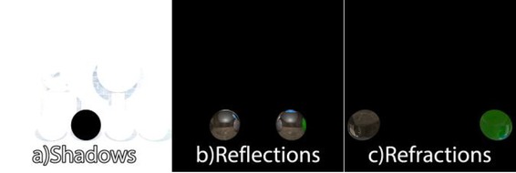
An example of textures generated during ray tracing stage: a) shadow, b) reflection, c) refraction. The images were gamma corrected so the results are clearly visible
Additionally, ray tracing stage is responsible for generation skybox values in case there is no object in camera view. Although as for primary rays we can use G-Buffer data, every next ray must be tested against scene geometry. These result images are saved in special buffers and are passed in last stage – blending stage.
3.4 The fourth stage – blending
This stage uses images generated in the first and the third stage in order to produce one, final image that will be presented to the user. This step is done again in OpenGL with usage of GLSL shader. To correctly blend images, four mentioned textures are being passed: lighting (L), shadows(S), reflection(M), refraction(R), and two additional textures from G-Buffer: optical properties and heuristic mask. Pseudo-code of blending stage is presented in listing 9. The vertex shader used in this stage is the same shader as in listing 4, and fragment shader used to generate final image containing all calculated effects is presented in listing 10.
Blending stage frame rendering function
Use shader for combining result textures into final image
Bind appriopriate textures from previous calculations
Draw screen quad ▹ produce final image, listing 10
Unbind textures
Swap display buffers
Blending stage fragment shader
input: texture coordinates itc
output: fragment color ofc
samplers: lighting texture lt, heuristic mask texture hmt, shadows texture st, reflections texture reflt refractions texture refrt, optical properties texture opt
lighting←tex(lt, itc)
heurVal←tex(hmt, itc)
if heurVal < 0.0001 then
ofc←lighting in sRGB color space
return
end if
opProp←tex(opt, itc)
lightingShadows←lighting - (vec4(1.0) - tex(st, itc))
reflCol←reflectivity * tex(reflt, itc) ▹ opProp.x is reflectivity
refrCol←transparency * tex(refrt, itc) ▹ opProp.z is opacity, so 1.0 - opProp.z is transparency
color1 ← reflCol + ((1.0 - reflectivity) * (refrCol + ((1.0 - transparency) * lightingShadows))) ▹ eq. (5)
color2←refrCol + ((1.0 - transparency) * (reflColr + ((1.0 - reflectivity) * lightingShadows))) ▹ eq. (6)
finalColor←(color1 + color2) * 0.5
ofc←finalColor in sRGB space
The combination goes as follow: if selected pixel was not marked by heuristic, pixel color is the same as from lighting texture. If not, we calculate color of lighting with applied shadows (C) using following equation.
Using this formula we receive lighting with darkened area, which were darker than white in shadow texture. We then calculate color of reflections (CM) and refractions (CR) considering given optical properties values for reflections (OM) and refractions (OR) (assuming refraction value equal 1.0 means full transparency) as follows.
Final color is taken as an average of CM and C R and as a last step gamma correction is finally applied. Such calculated image is a final form presented to user. Figure 6 presents final image for provided examples. Each of presented stages is repeated each frame until the end of application process.
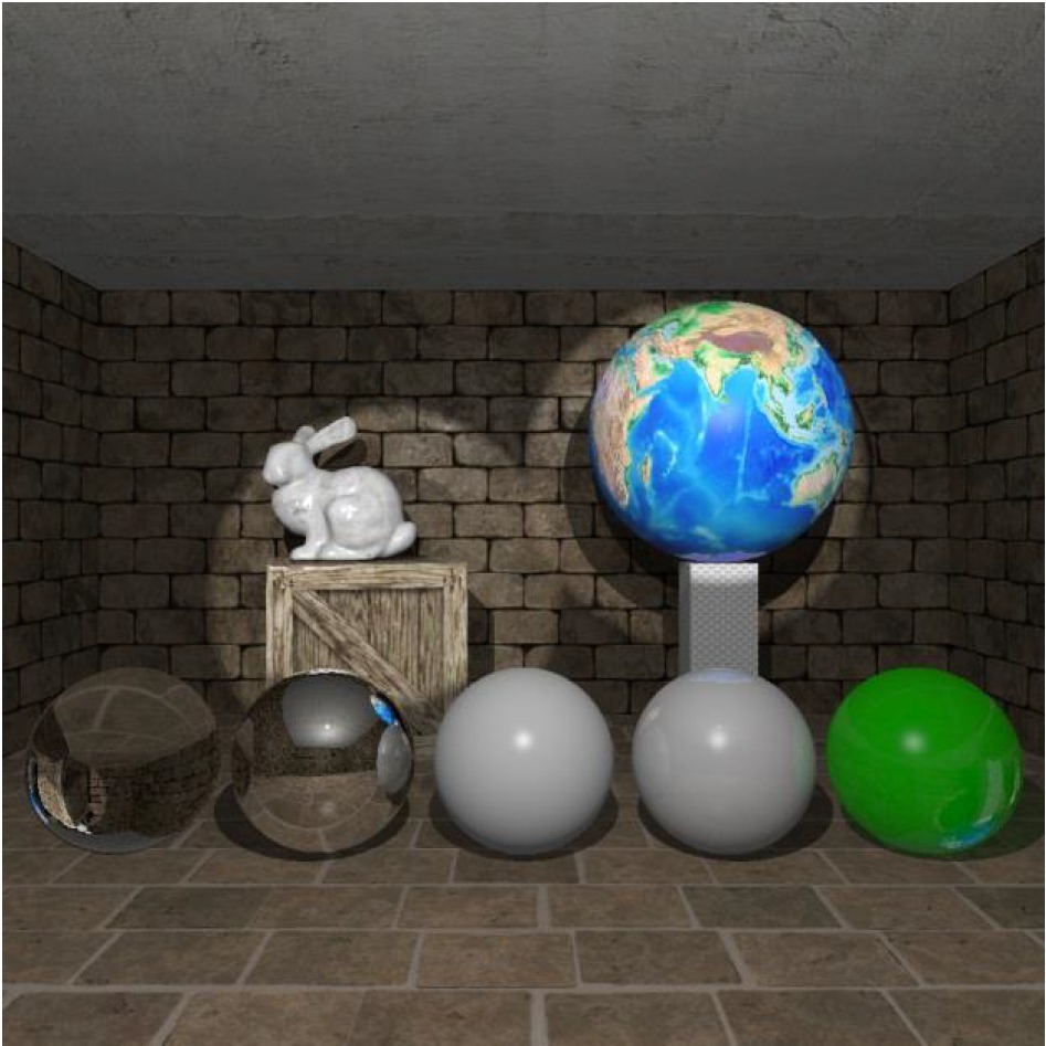
An example of final image generated during blending stage for example scene
4 Tests
In order to determine the correctness and performance of implementation of our solution for both hybrid rendering and heuristic, we have performed two sets of tests each performed in four different scenes. Each set consist of four scenes: Sponza scene with multiple reflective and refractive objects, Sponza scene with armadillo model using refractive material only, Dining Room Scene and Backyard Scene (Table 4). All performance measurements will be presented in average single frame rendering time.
Test scenes complexity information
| Scene | Sponza Spheres | Sponza Armadillo | Dining Room | Backyard |
|---|---|---|---|---|
| Vertices | 150704 | 160896 | 71697 | 1323288 |
| Triangles | 272144 | 292544 | 139378 | 1128786 |
| Objects | 29 | 25 | 27 | 48 |
| Reflective objects | 3 | 0 | 0 | 1 |
| Refractive objects | 23 | 21 | 1 | 2 |
The first set of tests consist of single, static image containing most of most important scene elements. We measured performance of our application, including performance of each rasterization stage, heuristic stage and ray tracing stage. We additionally tested our solution with performance of ray tracing only variant of our solution, where primary rays are generated from camera and are intersected against visible objects, and no heuristic is used for selecting appropriate objects for secondary effects.
The second set of tests consist of the same scenes being rendered by camera moving inside presented environment. The camera was moving using fixed path for 20 seconds. We compare performance for both runs with and without heuristic and compare obtained times in both camera traversals.
The tests and performance results were obtained using Lenovo IdeaPad Y700-15ISK notebook with 16 GB of RAM, Intel Core i7-6700HQ 2.60GHz CPU and NVIDIA GeForce GTX 960M GPU running on 64 bits version of Microsoft Windows 10 operating system. All tests were performed with application running with HD resolution (1280x720). As for heuristic settings, reflective and refractive objects in all scenes were set as relevant, and other parameters were adjusted to achieve frames per second (FPS) at a level of above 25 (frame rendered in less than 40ms). All typical graphical settings have been set to maximum (native textures resolution, texture 16x anisotropic filtering etc.). Information of each scene complexity is included in Table 4.
5 Results
Table 5 presents results of performance tests for the first set of tests, while Table 6 contains results regarding measurements in the second set of tests.
The first set of tests results (ms)
| Scene | Sponza Spheres | Sponza Armadillo | Dining Room | Backyard |
|---|---|---|---|---|
| FRAMEa | 35.991 | 38.713 | 38.032 | 38.632 |
| RASTb | 1.830 | 1.548 | 2.109 | 0.816 |
| HEURc | 6.686 | 7.037 | 5.223 | 14.862 |
| RAYTd | 26.778 | 29.319 | 30.618 | 22.215 |
| RAYT ONLY FRAMEe | 69.020 | 80.237 | 60.781 | 59.042 |
-
aFRAME – this value means the time of one full frame rendering time
bRAST – this value is the time of rasterization stage rendering
cHEUR – this value indicates how much time heuristic stage needed to calculate and create the graph and the data
dRAYT – this value shows how much time was spend in ray tracing stage
eRAYT ONLY FRAME – this is the time of rendering single frame when using ray tracing only to generate the whole image. No rasterization stage nor heuristic were used in this case
The second set of tests results (ms)
| Scene | Sponza Spheres | Sponza Armadillo | Dining Room | Backyard |
|---|---|---|---|---|
| Frame rendering time – with heuristic | 28.975 | 33.694 | 37.925 | 33.263 |
| Frame rendering time – no heuristic | 52.769 | 64.373 | 47.097 | 45.223 |
As it can be seen in Table 5 our solution maintained to obtain at least 25 FPS in each test scene. Of course, the sum of values from three stages does not give the frame rendering values, because there are some minor phases in between like final image compositing or input handling, which were not measured individually. For each test scene, there is a high gain in comparison with ray tracing only variant. The gain varies from 1.529 ms for Backyard scene following 1.598 ms for Dining Room, then 1.918 ms for Sponza with spheres and to 2.073 ms as for Sponza with armadillo scene which means our solution can be even two times faster than ray tracing only. One can also see that along with the increasing amount and complexity of objects the time spend on heuristic is also increased. This is caused by the fact that heuristic has to calculate how much screen space does the object cover, and then create and analyze the graph of all visible objects. The way of decreasing time of heuristic calculations may be one of the issues to investigate.
Analyzing Table 6 we can see that using heuristic allowed to maintain average FPS during traversals above 25, while without heuristic the results were worse. The difference in results between the first two tests and last two tests comes due to the fact that in the first two tests, reflective and refractive objects were main part of scene and were visible in camera most of time, while the Dining Room and Backyard scenes were traversed in more general way, with more objects receiving shadows only, which calculating task is computationally less demanding. However, our tests also showed that there are two problematic issues that poorly affects performance of our solution. One of the issue are reflective or refractive objects that cover a significant part of the screen, which lead to high performance drop due to demanding ray tracing calculations for many pixels. Of course, our heuristic can detect such situations and decide to avoid rendering of effects for such object for maintaining performance reason, but this poorly affects visual experience of image because this object loses its details while being clearly visible. The solution of this would be to investigate and detect the performance bottleneck and develop a way to bypass it, or apply some other, less computationally demanding method of obtaining those effects. The second problematic matter are multiple refractive objects that are close to each other one by one, like e.g. leaves of photorealistic tree model using alpha mask. Rays recursively hit each object and calculate its visual look and whether calculate further transparency, causing massive performance drop. In case of mentioned tree, the solution would be to make the rendering pipeline know, how to deal with object’s transparency and instead of ray tracing, calculate it during rasterization stage using alpha blending technique. As for refractive objects, there is still a gap on how to deal with them so environment would not have to be simplified in order to maintain performance. Visual effects have been shown in the Figures 7, 8, 9 and 10.
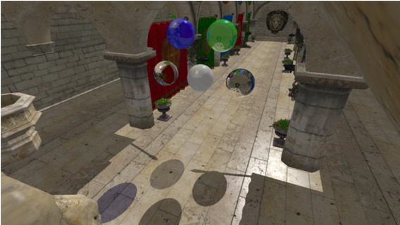
Image of the first test scene – Sponza with multiple reflective and refractive spheres. Note that due to heuristic decisions shadows of objects that are further away are not rendered
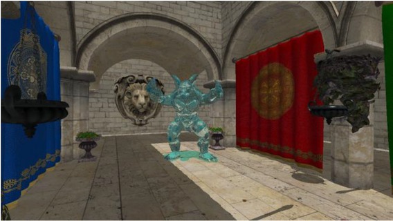
Image of the second test scene – Sponza with refractive armadillo statue
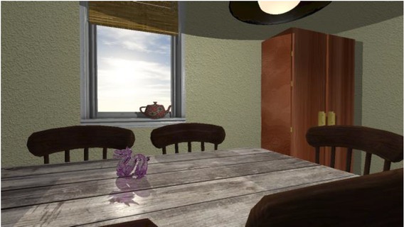
Image of the third test scene – Dining Room. There are two light sources in this scene
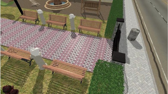
Image of the fourth test scene – Backyard. An example of ray tracing generating detailed shadows for complicated objects
One issue not tested in our paper is the user visual experience of scenes with heuristic enabled. Of course, our heuristic tries to select most relevant objects from the point of view of human perception, but it would be valuable to check how noticeable changes of object secondary effects would be in certain scenarios. This is important as the case when close, relevant object appears on the screen, the heuristic may decide not to render effects object’s that were further away from observer and to this point were having those effects calculated. This can be also reduced by spending more time on appropriate heuristic values setting for both heuristic and objects as those are affecting the heuristic behavior mostly. The best way to perform such measurement would be to use Eye Tracking System and ask people with some tasks to do in virtual environment.
Despite those issues our tests indicates that presented solution is capable of making ray tracing a method that may be used in real-time interactive applications, especially with the use of high-end graphic cards which computing power is even bigger than the tested one.
6 Conclusions
We have described a hybrid approach of rendering virtual environments with the use of both rasterization which use in real-time environments is common and ray tracing which allows simpler generation of any secondary image effects along with heuristic that determines objects which will have shadows, reflections and refractions rendered based on theirs relevance and processing cost. We also described how this heuristic is designed, what parameters is taking into account and how data is passed to other stages.
Nowadays, with the use of modern high-end GPU it is now possible to perform ray tracing along with rasterization stage and maintain real-time characteristic of application. Usage of G-Buffer structure as replacement of primary rays generation comes is a very good optimization that in cost of higher memory demand, which is no longer such a big issue, allows to omit one of the computationally expensive phase of rays intersection. There are some cases that are problematic, like many complex objects with secondary effects near each other that may cause performance drop, but with appropriate optimization of rendering pipeline or use of properly configured heuristic this problem can be overcome.
There are many ways of further development that can be proposed as future work. As for application in general, it was currently designed as a rendering program, however, with a few changes in architecture, it could be easily adopted as a prototype of game engine, and its performance when used in a game could be investigated. This would require implementation of support of different animations for objects. As another way of research, it would be interesting to investigate how hybrid rendering would work when replace ray tracing with other rendering methods, including those with global illumination effects like path-tracing, metropolis light transport, photon mapping, radiosity or any of monte carlo methods and measure performance of both application and heuristic. It would also be valuable to explore how additional effects like e.g. ambient occlusion, anti-aliasing, tessellation or post-processing filters would affect both performance and image quality.
As for rasterization stage it would be worth to implement different effects. It would be interesting to incorporate better illumination models other than Blinn-Phong, especially these that comes from physical based rendering (PBR). Other effects includes implementation of high dynamic range (HDR), more specific textures support, like e.g. height maps or other rendering optimizations including frustum culling and level of detail (LOD).
As presented in this paper, our heuristic configuration highly depends on its configuration by designer. The overall computing time can be designed as a Graphic Setting that has few pre-defined steps that is selected by user, but per object parameters are still configurable during scene creation. In future work it could be redesigned and automated so it could work and determine both relevancy and specific costs without need of explicit pass of values by scene designer. Currently, our heuristic decides binary whether to calculate all or none secondary effects for specific object. In future it could be done per effect, so some objects could have e.g. reflections calculated, but not the shadows etc., depending on available time and object’s parameters. The heuristic could also decide on secondary effects calculated on recursive rays of reflections and refractions, because currently those are not affected by heuristic and ray tracing recursive rays calculates all secondary effects. Additionally, some other variations of heuristic could be deployed, with some additional factors being taken into account during its calculations.
Currently, ray tracing stage responsible for shadows generates hard shadows only. There is possibility to investigate some algorithms of generating soft shadows considering their complexity and quality of such generated shadows. An additional research on currently created scene’s graph using OptiX’s provided data structure and selected acceleration structures may be required in order to further improve performance of this stage and accelerate ray with scene geometry intersection calculations. OptiX does not provide support for mipmapping and ray traced effects may have visible noise, or tangent and bitangent calculations, so normal maps are not used, so extending ray tracing pipeline by methods providing these functionalities would positively influence ray traced effects visual aspect. Currently, our application is limited for use only on computers equipped with NVIDIA Graphic Card, due to the fact that OptiX uses CUDA, which are not supported in cards of other vendors. It would be very interesting and valuable to re-implement application using recent ray tracing API mentioned in related work. With either DXR or NVIDIA RTX, which are new API specialized in ray tracing algorithms, their usage could result in further performance and image quality increase.
To sum up, hybrid rendering is a promising topic and research shows, that its use is wide and can be customized depending on target application, requirements, restrictions and hardware. With further development of computer architecture, with particular emphasis on GPU’s, it will be possible to easily overcome difficulties related to specific rendering issues and methods using well-optimized and correctly implemented techniques and quality of rendered images in terms of both photorealistic result and user experience will increase. It shows that, despite the apparent impression that we reach to the limits of what Computer Graphics may offer, there will always be a field to discover some new ways of improvements of current state of the art and using and combining different approaches may still turn out as beneficial and improve known method in either performance or quality aspect particularly or in general.
References
[1] Manocha D., General-Purpose Computations Using Graphics Processors, Computer, 2005, vol. 38, no. 8, 85-8810.1109/MC.2005.261Search in Google Scholar
[2] Purcell T.J., Buck I.,Mark W.R., Hanrahan P., Ray tracing on programmable graphics hardware, ACM Transactions on Graphics, Proceedings of ACM SIGGRAPH 2002, 2002, 21 (3), 703-71210.1145/566654.566640Search in Google Scholar
[3] Bigler J., Stephens A., Parker S.G., Design for parallel interactive ray tracing systems, Interactive Ray Tracing 2006, IEEE Symposium on, IEEE, 2006, 187-19610.1109/RT.2006.280230Search in Google Scholar
[4] Nickolls J., Buck I., Garland M., Skadron K., Scalable parallel programming with CUDA, Queue - GPU Computing, 2008, vol. 6 Issue 2, 40-5310.1145/1365490.1365500Search in Google Scholar
[5] Parker S.G., Bigler J., Dietrich A., Friedrich H., Hoberock J., Luebke D., McAllister D., McGuire M., Morley K., Robison A., Stich M., Optix: a general purpose ray tracing engine, ACMTransactions on Graphics (TOG), 2010, 29(4), 66, https://raytracing-docs.nvidia.com/optix_6_0/whitepaper/nvidia_optix_TOG_v29_n4.pdf10.1145/1833349.1778803Search in Google Scholar
[6] Wojciechowski A., Camera navigation support in a virtual environment, Bulletin of the Polish Academy of Sciences: Technical Sciences, https://doi.org/10.2478/bpasts-2013-0094 2013, 871-88410.2478/bpasts-2013-0094Search in Google Scholar
[7] Guzek K., Napieralski P., Eflcient rendering of caustics with streamed photon mapping, Bulletin of the Polish Academy of Sciences Technical Sciences, https://doi.org/10.1515/bpasts-2017-0040 2017, 361-36810.1515/bpasts-2017-0040Search in Google Scholar
[8] Deering M., Winner S., Schediwy B., Duffy C., Hunt N., The triangle processor and normal vector shader: a VLSI system for high performance graphics, ACM Siggraph computer graphics, 1988, vol. 22, no. 4, 21-3010.1145/54852.378468Search in Google Scholar
[9] Sundstedt V., Debattista K., Longhurst P., Chalmers A., Troscianko T., Visual attention for eflcient high-fidelity graphics, Proceedings of the 21st spring conference on Computer graphics, ACM, 2005, 169-17510.1145/1090122.1090150Search in Google Scholar
[10] Yan S., El-Nasr S., Visual attention in 3D video games, in: Proceedings of the 2006 ACM SIGCHI international conference on Advances in computer entertainment technology, ACM, 2006, 2210.1145/1117309.1117327Search in Google Scholar
[11] Hasic J., Chalmers A., Saliency in motion: selective rendering of dynamic virtual environments, in: Proceedings of the 25th Spring Conference on Computer Graphics. ACM, 2009, 173-18010.1145/1980462.1980496Search in Google Scholar
[12] Whitted T., An improved illumination model for shaded display, in: Proceedings of the 6th annual conference on Computer graphics and interactive techniques (SIGGRAPH ’79), ACM, New York, NY, USA, 1979, 1410.1145/800249.807419Search in Google Scholar
[13] Popov S., Günther J., Seidel H.P., Slusallek P., Stackless KD-Tree Traversal for High Performance GPU Ray Tracing, in: Computer Graphics Forum, 2007, vol. 26, no. 3, 415-42410.1111/j.1467-8659.2007.01064.xSearch in Google Scholar
[14] Beck S., Bernstein A.-C., Danch D., Fröhlich B., CPU-GPU hybrid real time ray tracing framework, 2005Search in Google Scholar
[15] Bak, P., Real time ray tracing. Master’s thesis, IMM, DTU, 2010Search in Google Scholar
[16] Chen C.C., Liu D.S.M., Use of hardware Z-buffered rasterization to accelerate ray tracing, in: Proceedings of the 2007 ACM Symposium on Applied Computing, New York, 2007, 1046-105010.1145/1244002.1244231Search in Google Scholar
[17] Hertel S., Hormann K., Westermann R., A hybrid GPU rendering pipeline for alias-free hard shadows, Eurographics 2009 Areas Papers, 2009, 59-66Search in Google Scholar
[18] Cater K., Chalmers A., Ledda P., Selective quality rendering by exploiting human inattentional blindness: looking but not seeing, in Human Factors, ACM, 2002, 17-2410.1145/585740.585744Search in Google Scholar
[19] Cater K., Chalmers A., Ward G., Detail to attention: exploiting visual tasks for selective rendering, in: EGRW-Proceedings of the 14th Eurographics workshop on Rendering Techniques, Eurographics Association, 2003, 270-280Search in Google Scholar
[20] Hu W., Huang Y., Zhang F., Yuan G., Li W., Ray tracing via GPU rasterization. The Visual Computer, 2014, 30 (6-8), 697-70610.1007/s00371-014-0968-8Search in Google Scholar
[21] de Macedo D.V., Rodrigues, M.A.F. (2014). A Hybrid Rendering Engine for Generating Real-Time Dynamic Shadows in Computer Games, in: XIII Sympósio Brasileiro de Jogos e Entretenimento Digital (SBGAMES), Trilha de Computacçao, Porto Alegre, SBC, 2014, vol. 1, 938-941Search in Google Scholar
[22] de Macedo D.V., Rodrigues, M.A.F., Realistic Rendering in 3DWalkthroughs with High Quality Fast Reflections, in: Computer Games and Digital Entertainment (SBGames), 2015 14th Brazilian Symposium on, IEEE, 2015, 109-11710.1109/SBGames.2015.23Search in Google Scholar
[23] de Macedo, D. V., Rodrigues, M.A.F. (2016). Comparison of Acceleration Data Structures for High Quality Fast Reflections of Static and Deformable Models in Walkthrough Animations. SBC Journal on Interactive Systems, 7(1), 28-37.10.5753/jis.2016.667Search in Google Scholar
[24] deMacedo D.V., Rodrigues, M.A.F., Real-time dynamic reflections for realistic rendering of 3D scenes, The Visual Computer, 2016, 1-1010.1007/s00371-016-1335-8Search in Google Scholar
[25] Ludvigsen H., Elster, A.C., Real-Time Ray Tracing Using Nvidia OptiX, in: Eurographics (Short Papers), 2010, 65-68Search in Google Scholar
[26] Sabino T.L.R., Andrade P., Lattari L.G., Clua E., Montenegro A., Pagliosa P. A., Eflcient use of in-game ray-tracing techniques. In SBC-Proceedings of SBGames, 2011Search in Google Scholar
[27] Sabino T.L.R., Uma Arquitetura de Pipeline Híbrida para Rasterizac˛ao e Trac˛ado de Raios em Tempo Real. ic. uff. br., 2012Search in Google Scholar
[28] Sabino T.L., Andrade P., Clua E.W.G., Montenegro A., Pagliosa P., A hybrid GPU rasterized and ray traced rendering pipeline for real time rendering of per pixel effects, in: International Conference on Entertainment Computing, Springer, Berlin, Heidelberg, 2012, 292-30510.1007/978-3-642-33542-6_25Search in Google Scholar
[29] Andrade P.M.F., Sabino T.L., Clua E.W.G., Pagliosa P. A., A heuristic to selectively ray trace light effects in real time, SBGames, 2012, 2-5Search in Google Scholar
[30] Andrade P., Sabino T., Clua E., Towards a heuristic based real time hybrid rendering a strategy to improve real time rendering quality using heuristics and ray tracing, in: Computer Vision Theory and Applications (VISAPP), 2014 International Conference on, IEEE, 2014, vol. 3, 12-2110.5220/0004691300120021Search in Google Scholar
[31] Andrade P., Clua E., Sabino T., Forti F., A Heuristic Approach to Render Ray Tracing Effects in Real Time for First-Person Games, SBC Journal on Interactive Systems, 2014, 5 (1), 26-3310.5753/jis.2014.640Search in Google Scholar
[32] Andrade P., Sabino T., Clua E., Pagliosa P., Ray-Traced Reflections in Real-Time Using Heuristic Based Hybrid Rendering, in: Computer Games and Digital Entertainment (SBGAMES), 2014 Brazilian Symposium on, IEEE, 2014, 240-24810.1109/SBGAMES.2014.34Search in Google Scholar
[33] Frid Kastrati M., Hybrid Ray-Traced Reflections in Real-Time: in OpenGL 4.3, 2015Search in Google Scholar
[34] Frid Kastrati M., Goswami P., Selective rasterized ray-traced reflections on the GPU, in: Smart Tools and Apps in Computer Graphics (STAG), Genova, Italy. Eurographics-European Association for Computer Graphics, 2016Search in Google Scholar
[35] LeeW.J.,Hwang S.J., Shin Y., Yoo J.J., Ryu S., An eflcient hybrid ray tracing and rasterizer architecture for mobile GPU, in: SIGGRAPH Asia 2015 Mobile Graphics and Interactive Applications, ACM, 2015, 210.1145/2818427.2818442Search in Google Scholar
[36] Marrs A., Spjut J., Gruen H., Sathe R., McGuire M., Proceedings of the Conference on High-Performance Graphics - HPG’18, 2018Search in Google Scholar
[37] Gałaj T., Wojciechowski A., A Study on Image Comparison Metrics for Atmospheric Scattering Phenomenon Rendering, Computer Vision and Graphics, Springer International Publishing, https://doi.org/10.1007/978-3-030-00692-1_4,2018,38-4710.1007/978-3-030-00692-1_4Search in Google Scholar
[38] Upchurch P., Desbrun M., Tightening the precision of perspective rendering, Journal of Graphics Tools, 2012, vol. 16, no. 1, 40-5610.1080/2151237X.2012.649987Search in Google Scholar
© 2019 P. Walewski et al., published by De Gruyter
This work is licensed under the Creative Commons Attribution 4.0 International License.
Articles in the same Issue
- Regular Articles
- Non-equilibrium Phase Transitions in 2D Small-World Networks: Competing Dynamics
- Harmonic waves solution in dual-phase-lag magneto-thermoelasticity
- Multiplicative topological indices of honeycomb derived networks
- Zagreb Polynomials and redefined Zagreb indices of nanostar dendrimers
- Solar concentrators manufacture and automation
- Idea of multi cohesive areas - foundation, current status and perspective
- Derivation method of numerous dynamics in the Special Theory of Relativity
- An application of Nwogu’s Boussinesq model to analyze the head-on collision process between hydroelastic solitary waves
- Competing Risks Model with Partially Step-Stress Accelerate Life Tests in Analyses Lifetime Chen Data under Type-II Censoring Scheme
- Group velocity mismatch at ultrashort electromagnetic pulse propagation in nonlinear metamaterials
- Investigating the impact of dissolved natural gas on the flow characteristics of multicomponent fluid in pipelines
- Analysis of impact load on tubing and shock absorption during perforating
- Energy characteristics of a nonlinear layer at resonant frequencies of wave scattering and generation
- Ion charge separation with new generation of nuclear emulsion films
- On the influence of water on fragmentation of the amino acid L-threonine
- Formulation of heat conduction and thermal conductivity of metals
- Displacement Reliability Analysis of Submerged Multi-body Structure’s Floating Body for Connection Gaps
- Deposits of iron oxides in the human globus pallidus
- Integrability, exact solutions and nonlinear dynamics of a nonisospectral integral-differential system
- Bounds for partition dimension of M-wheels
- Visual Analysis of Cylindrically Polarized Light Beams’ Focal Characteristics by Path Integral
- Analysis of repulsive central universal force field on solar and galactic dynamics
- Solitary Wave Solution of Nonlinear PDEs Arising in Mathematical Physics
- Understanding quantum mechanics: a review and synthesis in precise language
- Plane Wave Reflection in a Compressible Half Space with Initial Stress
- Evaluation of the realism of a full-color reflection H2 analog hologram recorded on ultra-fine-grain silver-halide material
- Graph cutting and its application to biological data
- Time fractional modified KdV-type equations: Lie symmetries, exact solutions and conservation laws
- Exact solutions of equal-width equation and its conservation laws
- MHD and Slip Effect on Two-immiscible Third Grade Fluid on Thin Film Flow over a Vertical Moving Belt
- Vibration Analysis of a Three-Layered FGM Cylindrical Shell Including the Effect Of Ring Support
- Hybrid censoring samples in assessment the lifetime performance index of Chen distributed products
- Study on the law of coal resistivity variation in the process of gas adsorption/desorption
- Mapping of Lineament Structures from Aeromagnetic and Landsat Data Over Ankpa Area of Lower Benue Trough, Nigeria
- Beta Generalized Exponentiated Frechet Distribution with Applications
- INS/gravity gradient aided navigation based on gravitation field particle filter
- Electrodynamics in Euclidean Space Time Geometries
- Dynamics and Wear Analysis of Hydraulic Turbines in Solid-liquid Two-phase Flow
- On Numerical Solution Of The Time Fractional Advection-Diffusion Equation Involving Atangana-Baleanu-Caputo Derivative
- New Complex Solutions to the Nonlinear Electrical Transmission Line Model
- The effects of quantum spectrum of 4 + n-dimensional water around a DNA on pure water in four dimensional universe
- Quantum Phase Estimation Algorithm for Finding Polynomial Roots
- Vibration Equation of Fractional Order Describing Viscoelasticity and Viscous Inertia
- The Errors Recognition and Compensation for the Numerical Control Machine Tools Based on Laser Testing Technology
- Evaluation and Decision Making of Organization Quality Specific Immunity Based on MGDM-IPLAO Method
- Key Frame Extraction of Multi-Resolution Remote Sensing Images Under Quality Constraint
- Influences of Contact Force towards Dressing Contiguous Sense of Linen Clothing
- Modeling and optimization of urban rail transit scheduling with adaptive fruit fly optimization algorithm
- The pseudo-limit problem existing in electromagnetic radiation transmission and its mathematical physics principle analysis
- Chaos synchronization of fractional–order discrete–time systems with different dimensions using two scaling matrices
- Stress Characteristics and Overload Failure Analysis of Cemented Sand and Gravel Dam in Naheng Reservoir
- A Big Data Analysis Method Based on Modified Collaborative Filtering Recommendation Algorithms
- Semi-supervised Classification Based Mixed Sampling for Imbalanced Data
- The Influence of Trading Volume, Market Trend, and Monetary Policy on Characteristics of the Chinese Stock Exchange: An Econophysics Perspective
- Estimation of sand water content using GPR combined time-frequency analysis in the Ordos Basin, China
- Special Issue Applications of Nonlinear Dynamics
- Discrete approximate iterative method for fuzzy investment portfolio based on transaction cost threshold constraint
- Multi-objective performance optimization of ORC cycle based on improved ant colony algorithm
- Information retrieval algorithm of industrial cluster based on vector space
- Parametric model updating with frequency and MAC combined objective function of port crane structure based on operational modal analysis
- Evacuation simulation of different flow ratios in low-density state
- A pointer location algorithm for computer visionbased automatic reading recognition of pointer gauges
- A cloud computing separation model based on information flow
- Optimizing model and algorithm for railway freight loading problem
- Denoising data acquisition algorithm for array pixelated CdZnTe nuclear detector
- Radiation effects of nuclear physics rays on hepatoma cells
- Special issue: XXVth Symposium on Electromagnetic Phenomena in Nonlinear Circuits (EPNC2018)
- A study on numerical integration methods for rendering atmospheric scattering phenomenon
- Wave propagation time optimization for geodesic distances calculation using the Heat Method
- Analysis of electricity generation efficiency in photovoltaic building systems made of HIT-IBC cells for multi-family residential buildings
- A structural quality evaluation model for three-dimensional simulations
- WiFi Electromagnetic Field Modelling for Indoor Localization
- Modeling Human Pupil Dilation to Decouple the Pupillary Light Reflex
- Principal Component Analysis based on data characteristics for dimensionality reduction of ECG recordings in arrhythmia classification
- Blinking Extraction in Eye gaze System for Stereoscopy Movies
- Optimization of screen-space directional occlusion algorithms
- Heuristic based real-time hybrid rendering with the use of rasterization and ray tracing method
- Review of muscle modelling methods from the point of view of motion biomechanics with particular emphasis on the shoulder
- The use of segmented-shifted grain-oriented sheets in magnetic circuits of small AC motors
- High Temperature Permanent Magnet Synchronous Machine Analysis of Thermal Field
- Inverse approach for concentrated winding surface permanent magnet synchronous machines noiseless design
- An enameled wire with a semi-conductive layer: A solution for a better distibution of the voltage stresses in motor windings
- High temperature machines: topologies and preliminary design
- Aging monitoring of electrical machines using winding high frequency equivalent circuits
- Design of inorganic coils for high temperature electrical machines
- A New Concept for Deeper Integration of Converters and Drives in Electrical Machines: Simulation and Experimental Investigations
- Special Issue on Energetic Materials and Processes
- Investigations into the mechanisms of electrohydrodynamic instability in free surface electrospinning
- Effect of Pressure Distribution on the Energy Dissipation of Lap Joints under Equal Pre-tension Force
- Research on microstructure and forming mechanism of TiC/1Cr12Ni3Mo2V composite based on laser solid forming
- Crystallization of Nano-TiO2 Films based on Glass Fiber Fabric Substrate and Its Impact on Catalytic Performance
- Effect of Adding Rare Earth Elements Er and Gd on the Corrosion Residual Strength of Magnesium Alloy
- Closed-die Forging Technology and Numerical Simulation of Aluminum Alloy Connecting Rod
- Numerical Simulation and Experimental Research on Material Parameters Solution and Shape Control of Sandwich Panels with Aluminum Honeycomb
- Research and Analysis of the Effect of Heat Treatment on Damping Properties of Ductile Iron
- Effect of austenitising heat treatment on microstructure and properties of a nitrogen bearing martensitic stainless steel
- Special Issue on Fundamental Physics of Thermal Transports and Energy Conversions
- Numerical simulation of welding distortions in large structures with a simplified engineering approach
- Investigation on the effect of electrode tip on formation of metal droplets and temperature profile in a vibrating electrode electroslag remelting process
- Effect of North Wall Materials on the Thermal Environment in Chinese Solar Greenhouse (Part A: Experimental Researches)
- Three-dimensional optimal design of a cooled turbine considering the coolant-requirement change
- Theoretical analysis of particle size re-distribution due to Ostwald ripening in the fuel cell catalyst layer
- Effect of phase change materials on heat dissipation of a multiple heat source system
- Wetting properties and performance of modified composite collectors in a membrane-based wet electrostatic precipitator
- Implementation of the Semi Empirical Kinetic Soot Model Within Chemistry Tabulation Framework for Efficient Emissions Predictions in Diesel Engines
- Comparison and analyses of two thermal performance evaluation models for a public building
- A Novel Evaluation Method For Particle Deposition Measurement
- Effect of the two-phase hybrid mode of effervescent atomizer on the atomization characteristics
- Erratum
- Integrability analysis of the partial differential equation describing the classical bond-pricing model of mathematical finance
- Erratum to: Energy converting layers for thin-film flexible photovoltaic structures