Design of inorganic coils for high temperature electrical machines
-
Hamed Elmadah
 and
Noureddine Takorabet
and
Noureddine Takorabet

Abstract
The paper deals with a high frequency model of inorganic coils used to build high temperature (HT∘) motor. The HT∘ wire has a nickel layer that protects the copper against oxidation and a thin inorganic coating, which has poor electrical and mechanical properties. Therefore, the coils must be designed with a special care for getting a good distribution of turn-to-turn voltage during the fast transients excited by the steep fronted voltages of the PWM inverter.A specific coil structure is proposed and a high frequency (HF) equivalent circuit able to compute the turn-to-turn voltages during transients. The voltage distribution between the coils of a stator phase is also detailed.
1 Introduction
Generally speaking, electrical machines are widely used for many applications because of their accurate torque control capabilities and high power volume ration. However, the organic nature of their electrical insulation system (EIS) has a limited operating temperature, which depends on the expected lifetime. This concept is defined in standards by the temperature index [1]. A lot of research has been done to push this limit [2, 3, 4]. The very high temperature environments are until now forbidden for machine made with organic EISs, except for applications requiring a very short life times as smoke evacuation during the first minutes of fires [5, 6].
For surpassing the temperature limit imposed by polymers, it is possible to use inorganic EIS made without any polymer. Large machines are designed with thick textile EIS made with mica and fiberglass [7]. For small compact machines, wires are insulated with a thin ceramic layer [8] of more or less 10μm. This thin layer is not perfect; it has many microscopic cracks (≤ 1μm) [9]. For both cases, the high temperature (HT∘) insulating layers are not water-proof, they cannot protect the copper wire against oxidation at it is performed at lower temperatures by polymers. A nickel layer is added on the copper wire for avoiding copper oxidation.
Compared to the standard organic enamelled wires, the HT∘ wires have poor mechanical and electrical properties. The maximum turn-to-turn voltage is more or less 200 VRMS at 500∘C [9]. This limit must be compared to the usual values, which is more or less 600 VRMS for standard enameled wires at room temperature. Consequently for operating at standard voltages, the machine windings must provide a better voltage distribution between turns. The thin ceramic insulating layer is brittle; the wires must be protected by a HT∘ cement. Consequently, the inorganic coils are inflexible objects; this constraint must be considered for designing the stator core of HT∘ machines.
Soft magnetic laminated cores can operate up to 500∘C when the designer accepts a slight reduction of the flux density. the magnetic sheets must be insulated by their natural oxidation [10, 11].
A recent studies dealing with HT∘ machines show the limits of each structure. For the induction motor, the first limit is the complex shapes required for the distributed windings [12, 13]. The second one is related to the rotor cage resistance which increases with temperature. The rotor losses increase the temperature and the resistance; this cumulative effect may cause a lack of stability in addition of a poor efficiency. These drawbacks do not exist with permanent magnet synchronous machines (PMSM). Moreover, the winding can be made with one coil per stator slot, which is convenient with rigid inorganic coils [14].
With an inorganic HT∘ concentrated winding, the temperature limit of the PMSM depends on the magnet. The only magnets able to operate up to 500∘C are metallic ones, which have a very low coercive field, so they cannot
be used in PMSMs. Only few specific alloys of samarium and cobalt can be used in PMSMs up to 300 − 350∘C, but the limits of a reduced coercive field at high temperatures must be accepted [15]. Moreover, the rotor design must be made considering the high electric conductivity of these metallic magnets, they must be fragmented for getting limited losses due to flux density harmonics [16].
For exceeding the maximum temperature imposed by magnets, the synchronous reluctance machine (SRM) topologies can be used. The stator is similar but the rotor is only made of soft magnetic materials [17]. This machine is magnetized by the stator currents, the filling factor of stator slots becomes a more critical element of the design.
For every HT∘ motor topologies, the poor insulation properties of the ceramic coated wire must be compensated by a specific turn arrangement in coils [18]. The paper proposes a winding structure which makes it possible to feed the machine with usual voltages produced by PWM inverters despite the poor electrical performances of the ceramic coated wire. The method for building these coils is developed. The electrical stress distribution inside the coils and between coils is analyzed with high frequency (HF) equivalent circuits.
2 Synchronous reluctant machine topology
The inorganic coils are rigid objects without any flexibility. The stator slots must be opened for accepting prefabricated coils. The stator teeth must have a cuboid shape adapted to rigid coils. Thereby, the machine must be a doubly salient synchronous reluctance one. For a three-phase motor, the combination 12 slots - 10 poles is widely used for many applications. The 12 stator coils are divided into 3 phases which gives 4 coils per phase. But, with cuboid teeth in a cylindrical stator, there is a fairly large empty space between coils at the bottom of each slot. With 24 smaller teeth, this lost space is divided by about 2.
It it not obvious to produce rotating magneto-motive force (mmf) able to interact with the rotor for producing an average torque with a 24-slot stator and a very simple winding made of one coil per slot. This problem has been deeply studied for designing fractional-slot concentrated winding usually made with standard enameled wires [19, 20]. The principle consists in applying Fourier series to the mmf produced by the currents in coils. This analysis is made with two variables: the position of any point in the machine air-gap and the time. The Fourier analysis shows the existence of many mmf components; the only useful one, able to produce an average torque, must have a number of magnetic poles equal to the rotor mechanical poles. The other ones contribute to the torque ripple.
For a 3-phase 24-slot stator, the scientific literature offers 3 rotor possibilities for a doubly salient synchronous reluctance motor: 16 poles, 20 poles or 28 poles and the associates specific coil connections [20, 21, 22, 23]. The torque ripple is an important parameter to consider; especially because large vibrations can damage the rigid inorganic coils. Consequently, it is important to choose a structure that limits the torque ripples without increasing the complexity of the prototype. 2D simulations by finite elements (FE) were made for the three topologies, with the same geometrical input. The simulations show that the lowest torque ripples are obtained with the configuration 24 coils - 28 poles. However, this configuration requires a higher electric frequency at imposed speed because this motor has a higher pole-pair number. Eddy currents losses in iron are higher. Thus, the choice of 24-20 configuration is an acceptable compromise, which has torque ripple lower than the 24-16 configuration. After choosing the topology 24-20, the shape of the rotor teeth must be chosen. An optimization approach is adopted considering three parameters: the angular rotor teeth θ width, the sides of teeth inclination and air-gap extra thickness e. A parametric study made it possible to obtain elements that limit torque harmonics and the Figure 1 shows the three optimization parameters. Optimization results are θ = 8.1∘, = 10∘ and e = 0.05mm [24].
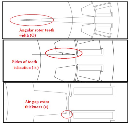
Rotor shape optimization parameters
Two solution have been implemented a massive rotor (Figure 2) and a laminated one (Figure 3). The massive rotor is made of steel, longitudinal slits have been added in
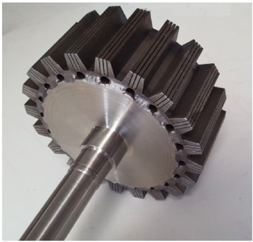
Massive iron rotor with longitudinal slits for limiting eddy currents.
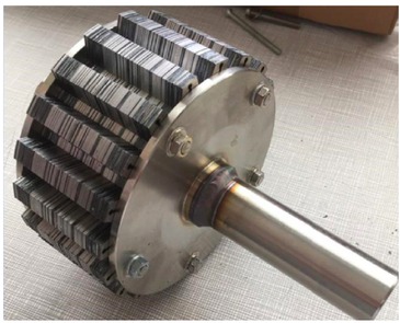
Laminated rotor made of FeSi magnetic sheets insulated by they natural oxidation.
the poles for limiting eddy currents due to rotating field harmonics. The laminated rotor is made of FeSi sheets insulated by their natural oxidation; their thicknesses is 0.5mm. The massive rotor has the advantage of being very strong and relatively easy to build with today’s machine tools. However, the main drawback of this technology is the higher eddy currents induced by the harmonic rotating fields. The laminated version is more difficult to manufacture; the FeSi sheets are cut by laser; they are compressed between two stainless steel flanges.
3 Structure of HT∘ inorganic coils
The brittle ceramic coated wires must be embedded in a HT∘ cement. The cement protect the conductors and contributes to the electrical isolation. The choice of a cement made of small grains (between 1μm and 44μm) and a correct application procedure is a necessary procedure for filling the voids between turns. After the thermal cycles, this cement becomes very hard and protect the ceramic insulated wires [25]. However the turn-to-turn breakdown voltage remains much lower than for low temperature organic enameled wires [9]. A good voltage distribution between turns is compulsory; it is ensured by a specific turn arrangement. Figure 4 presents such an arrangement for a 24 turn coil made of 8 transverse layers of 3 adjacent turns. The input wire is at the beginning of the inner turn near the stator tooth. The position of the output wire depends on the layer number : for a even layer number the the output wire is near the stator tooth; for an odd one it at the end of the outer layer. With 8 layers of 3 turns, the maximum turn-to-turn voltage corresponds to the induced voltage in 5 turns.
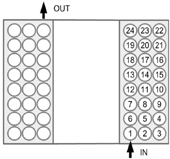
Turn position inside the HT∘ inorganic coil inspired form the high voltage transformer technology.
This structure is realized with the plastic support of Figure 5 made by a 3D printer. The upper part defines the position of each turn in a layer; it can be removed from the lower part made of several "U" that correspond to the half of the stator slot width. When the upper part is removed, the three turn layer falls in the lower part of the plastic support. The picture of Figure 5 is made when the upper part is in the position for receiving the turns of an even layer; it is returned for making the odd ones. When the 8 layers have been placed in the lower part of the plastic support, they are carefully transferred in a stainless steel mold designed for defining the coil sizes. Figure 6 shows the mold containing a coil. The output wire is placed in front of the outer turn, for a even number of turn it must cross the end of the coil creating a small extra height of the coil end.

Plastic support defining the position of the tuns of a layer.
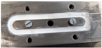
Stainless steel mold defining the shape of inorganic coils.
A strict protocol, based on the acquired experience and the instructions of the cement data sheet, must be applied for getting a coil without any crack and few residual voids. The cement hardening must be progressive in the mold. The process of cement grain growth, which makes the final hardness, is achieved by the last thermal cycle at 370∘C. The 10 phases of the protocol can be summarized in the following list.
turn placing in the plastic support;
preparation of a small quantity of HT∘ cement;
laying a sheet of mica (50μm) on the internal walls of the mold;
transfer of the coil in the mold;
injection of the cement ;
24 hours in a dry low pressure atmosphere;
first thermal cycle of 7 hours at 50∘C;
second thermal cycle of 5 hours at 70∘C;
third thermal cycle of 2 hours at 120∘C;
final hardening cycle of 4 hours at 370∘C.
Figure 7 shows an example for HT∘ coil. Small surface irregularities subsist, they are cause by an imperfect injection of cement into the mold. However the coils are very hard objects without any deep crack; it is very difficult to scratch them with a screwdriver.
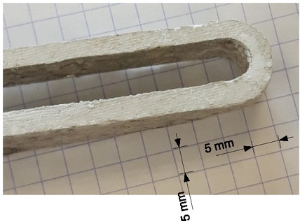
Example of a HT∘ coil at the size of the 24-20 SRM prototype.
4 Turn-to-turn voltage distribution in a coil
4.1 Fast phenomena analysis with an equivalent circuit
Transient phenomena due to the fast-fronted voltage of PWM patterns. These fast phenomena can be analyzed with a full wave 3D electromagnetic model. This approach is rather complex and time consuming; a simpler one can be used considering that each turn of the coil is much shorter than the wave length at the the highest frequency of the analysis. In these conditions, the analysis can be made with equivalent circuits defined at the turn level. Supposing that the wave length must be at least 10 times the average turn length, the minimum wave length is 1.2m. For an insulating material, which permittivity is 10, the propagation speed of a plane wage is 95 106 m/s; the maximum frequency for the analysis at the turn level is 79MHz, which is very high for the transient analysis of a motor coil.
Each turn is considered as an indivisible entity coupled to the others by the magnetic field (self and mutual inductances), and electric fields (capacitances). Figure 8 shows the part of this equivalent circuit corresponding to the first 9 turns of the HT∘ coil. The nodes with a number are the turns inputs defined in Figure 4. For each turn, an additional node connects the equivalent resistance representing the HF losses. The mutual inductances between turns are not presented but they are taken into account by a 24x24 inductance matrix. This equivalent circuit can be simulated by a Spice processor.
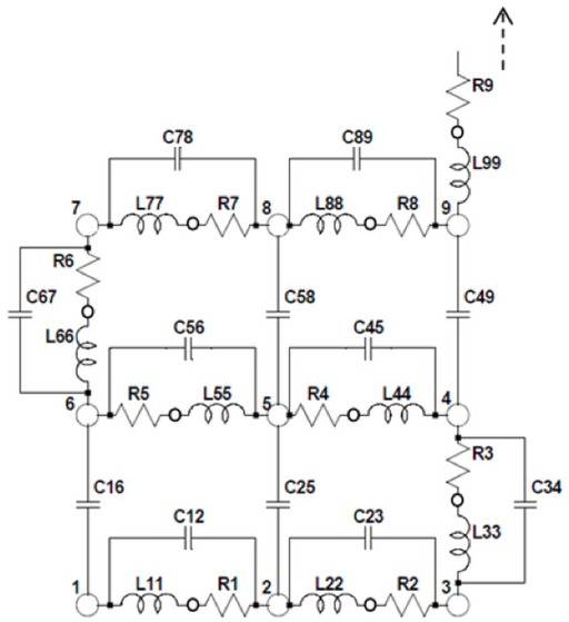
Spice equivalent circuit of a HT∘ coil.
Figure 9 shows the impedance modulus of two inorganic coils measured with an impedance analyzer from 100kHz to 100MHz. The curves are superimposed up to about 5MHz; the natural frequencies are very close to 10MHz, with a small difference due to variations of the actual turn positions which change the turn-to-turn capacitances. The main phenomena are observed at about 10MHz, which is much under the model principle limit. The transient analysis can be made with wit an equivalent circuit built at the turn level.
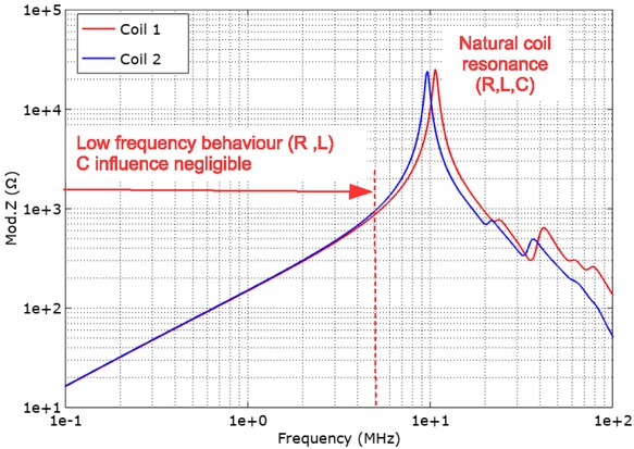
Impedance spectra of two HT∘ coils. The main resonance is at more or less 10 Hz.
The capacitances values are estimated using a specific coil made of two unconnected sets of 2 layers of 3 turns is used as a test bench. The building process is the same. Because of the 3 adjacent turns of the test bench, the turn-to-turn capacitance, estimated to 1/3 of the experimental value, is 7 pF. This value is confirmed by a 2D electrostatic simulation of two adjacent ceramic coated wires placed in a HT∘ cement.
4.2 Magnetic couplings
The inductance matrix is computed by a linear magneto-harmonic 2D finite element simulation. The laminated magnetic tooth in the center of the coil is not taken into account because a short experimental investigations shows that the coil natural frequency does not change significantly when it is placed on a stator tooth. This phenomena is explained by the strong skin effect in the stator magnetic tooth [26]. It is considered for the analysis made at the level of the full stator winding. However the influence of the nickel layer protecting the copper from oxidation is considered. The mesh must be very thin in the nickel layer for taking skin effects into account. The size of the mesh must under 1/3 of the estimated skin depth in nickel. By supplying a single turn, the self-inductance and mutual inductances are determined by calculating the flux of each turn.
The materials are supposed linear and defined by their resistivities and relative permeabilities (ρ = 1.72 10−8 Ω.m and μR = 1 for the copper; ρ = 8.7 10−8 Ω.m and μR = 25 for the nickel [27]); the thickness of the nickel layer is 65 μm; the wire diameter is 1mm. Figures 10 and 11 show the simulation results when the first turn is supplied by a sine current of 1 A peak. These figures show the flux density at t = 0, which is null at the centre points of the fed wires; it is positive inside the coil and negative outside. The nickel layer of each wire concentrates the flux density because of its relative permeability. This concentration has an influence on the inductance values and on losses.
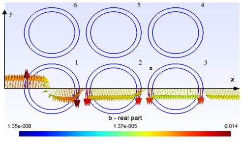
Color map of the flux density produced by 1Apeak in the turn 1.
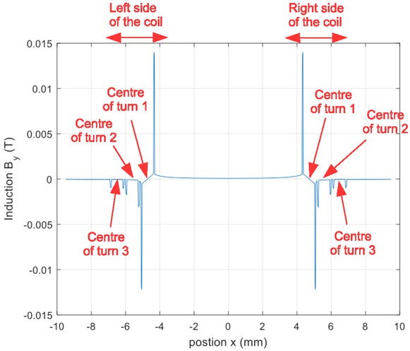
Y component of the flux density along a straight line at the center of the first layer for 1Apeak in turn 1.
Generally speaking, the inductance between the turns i and j, Lij, is defined as the ratio between the magnetic flux ϕ j in the tun j and a current Ii in the same turn (i = j, self inductance) of in another one (i ≠ j, mutual inductance) (1). Noting l the length of the coil and neglecting the end effects, the flux in a turn is given by (2).
The inductance matrix is computed using (2) and (1) when a current I flows in the single turn i. The eddy currents in the nickel layers create a phase shift between the flux and the current; consequently, (1) yields a complex number that imaginary parts are not always negligible. Table 1 presents the self inductance of the turn 1 and the 23 mutual inductances between the turn 1 and the others ones. The imaginary parts can be neglected for turns far from the fed one (over the 4th layer). Results are similar for results obtained when another turn is fed. Computations has been made at several frequencies between 100kHz and 800kHz, for the frequencies range where the turn-to-turn capacitance effects can be neglected. At these frequencies, the inductances matrix is almost constant.
Self and mutual inductances relative to the first turn
| layer | inner turn | middle turn | outer turn |
|---|---|---|---|
| 1 | 163−j11.6 nH | 54.3 − j2.2 nH | 35.0 − j1.0 nH |
| 2 | 53.1 − j2.3 nH | 45.2 − j2.3 nH | 31.4 − j0.5 nH |
| 3 | 32.6 − j0.5 nH | 31.3 − j0.4 nH | 25.0 − j0 nH |
| 4 | 22.5 − j0 nH | 22.4 − j0 nH | 19.8 − j0 nH |
| 5 | 16.3 − j0 nH | 16.6 − j0 nH | 15.4 − j0 nH |
| 6 | 12.2 − j0 nH | 12.5 − j0 nH | 12.2 − j0 nH |
| 7 | 9.0 − j0 nH | 9.5 − j0 nH | 9.6 − j0 nH |
| 8 | 6.6 − j0 nH | 7.1 − j0 nH | 7.4 − j0 nH |
Since all the imaginary parts are negative, the notation adopted is Lij = LijR − jLijI . The physical meaning of the inductance imaginary parts can be explained with an example that considers only the first turn and its impedance Z1 (3). It can be seen that the real part of the inductance produce the classical imaginary part of the impedance while the imaginary part correspond to a resistance due to eddy currents.
The real parts of the inductance matrix correspond to the Lii elements of the spice equivalent circuit presented in Figure 8 and of the magnetic couplings between these elements. The imaginary parts are used for estimating the Ri resistance values. These values are supposed to be the same for each turn. The turn resistance value is estimated neglecting the influence of the turn-to-turn capacitances. With this hypothesis, Figure 8 shows that the current is the same in all the turns. The matrix formulation (4) becomes simpler because I1 = I2 = ... = I24; the total flux Ψ is Ψ =
The turn resistance is the sum of the dc resistance Rdc and the effect of the imaginary part of the equivalent inductance. For a 24-turn coil this resistance is estimated by (6).
The experimental verification is not possible at the turn level because of the parasitic inductances introduced by connection wires. Therefore, it is made at the coil level comparing the global impedance computed with Spice and the measured one with an impedance analyzer. Results are presented in Figure 12
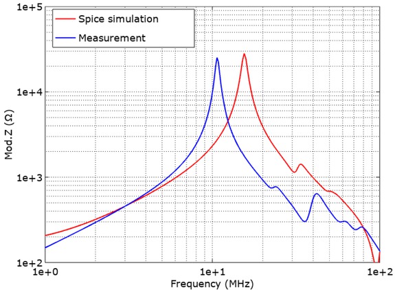
Spice model validation by a spectrum analysis of a whole coil.
The differences between the computed impedance and the measured one can be interpreted by the difficult estimation of the turn-to-turn capacitance,which depends on the average distances between turns.
The Spice model is used for computing the turn-to-ground voltage at each node of the equivalent circuit. Results are presented in Figure 13 for an input voltage of 100 V − 150 ns pulse imposed between the first turn input and the last one output. The rise and a fall times are set to 10 ns. The steady states are nearly reached at the end of the pulse; they show a linear voltage distribution between turns with steps of 1/24 (4.16%) of the pulse voltage.
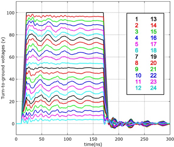
Transient voltage at the nodes of the Spice equivalent circuit.
The turn-to-turn voltages at any points of the coil are also computed. Figure 14 shows the voltage between successive adjacent turns. This figure presents two sets of curves depending to the difference between the turn numbers. The higher turn-to-turn voltages are obtained for differences between the turn numbers of 5 (solid lines); they
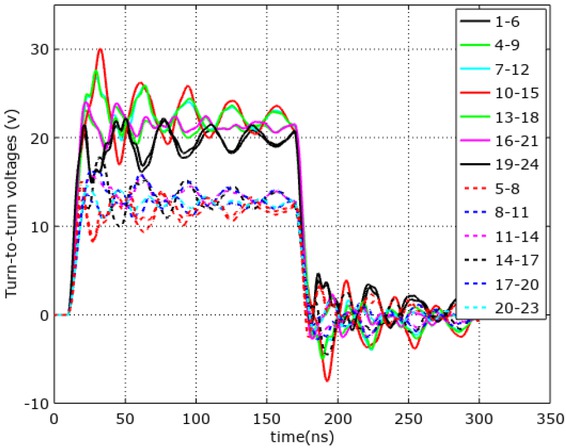
Transient turn-to-turn voltage for a coil voltage pulse of 100 V.
are lower when this difference is 3 (dotted lines). For a 100 V input pulse, the maximum peak voltage is 30 V (30%) between turns 10 and 15 at the coil centre, for a steady state of 20.8 V (5×4.16%). The results are very similar for a slightly larger distance between turns because the turn-to-turn capacitances decrease while all the self and mutual inductance increase.
5 Coil voltage estimation for an actual motor phase
5.1 Experimental approach
The voltage distribution between the stator coils during transients following the fast fronted voltages is measured experimentally. The 8 inorganic coils are placed on the stator teeth and connected as it is schematized in Figure 15. The star sign (*) denotes the coil winding direction: when a current enter in the star side, it creates a magnetic flux that enter in the corresponding stator tooth. The connections are made following the SRM 24-20 rules defined by the literature on fractional-slot concentrated-windings machines for providing a 20-pole rotating fundamental field when the stator is fed by a balanced 3-phase currents [20].
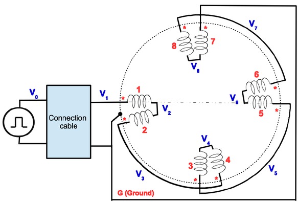
Motor phase coil connections for getting a 24-20-SRM.
The experimental set-up consists of a high voltage pulse generator connected between the input of the motor phase (coil 1); its output (coil 7). The ground point of the pulse generator is connected to the output of the motor phase and to the frame. The connection cable length is 1m. The voltage pulse must be over 360 V, which is the maximum pulse magnitude of the Phase-to-neutral voltage for a motor fed by a PWM inverter connected to a standard 540 V dc bus.
Measurements are made with a fast oscilloscope synchronized on the output voltage of the pulse generator (v0 in Figure 15). For this channel, measurements are made with a 1/100 − 350MHz passive probe. The ground point of the oscilloscope is connected to the ground point of the generator. The motor coil-to-ground voltages v1 − v8 are measured with the same broadband differential probe (100MHz). The pulse generator is tuned for producing 400 V − 4 μs pulses at a frequency of 10 kHz. The time lag between pulses is long enough for demagnetizing the stator core. Figure 16 presents the input pulse in a large time window. It can be seen that the pulse produced by the generator is not perfect; its magnitude is only 370 V for a generator tuned at 400 V because of the generator internal impedance. The voltage drop increase with time because of the current increase. The pulse slew rate is 4.28 kV/μs (the voltage reaches 300 V in 70 ns).
Input pulse used for measurements.
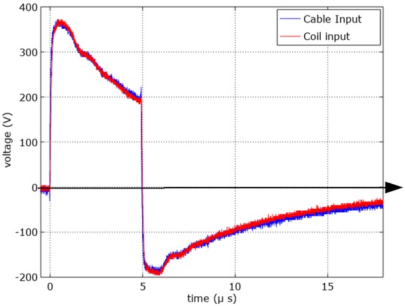
Figure 17 shows the cable input voltage (v0) and the voltages at each coil input (v1 − v8) in a time window corresponding the the transient state. The motor phase input voltage v1 has a fast ac component due to the connection cable transient superimposed to the source pulse voltage v0. The cable transient has a slight influence on v2 but none on the other voltages that has a slower transient state.
Transient voltage measurements at the coil level.
A careful observation of Figure 17 shows that the wave-forms are not classical damped sine waves with a natural angular frequency , a damping factor and a shift φ (e−αtsin(βt + φ). The system linearity must be tested. The same measurements were made for several pulse generator electromotive forces (emf). Figure 18 presents results. The coil-to-ground peak voltages are proportionals to the generator emf. Therefore, the system can be modelled by a linear equivalent circuit for voltages up to 450 V.
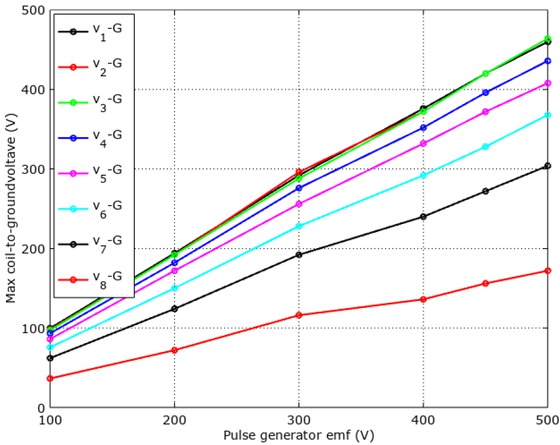
Peak voltage of the transient of each coil.
Figure 19 shows the voltages between the coil terminals. The first coil withstands a higher voltage than the other ones : 250 Vpeak rather than≃ 120 Vpeak for the others. This phenomena is the same for classical organic windings; the common mode capacitance (coil to ground) of the second coil remains uncharged during the pulse rise time; consequently, a large voltage appear at the terminals of the first coil during the very beginning of the transient.
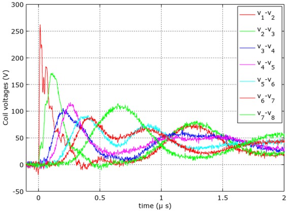
Transient voltage for each stator coil foe an actual pulse magnitide of 370 V.
5.2 Spice simulation
Figure 20 presents the Spice equivalent circuit of a motor phase. Every coil is modeled by RLC circuit; the resistance is computed considering the core HF losses; mutual inductances, which are not represented on the equivalent circuit,
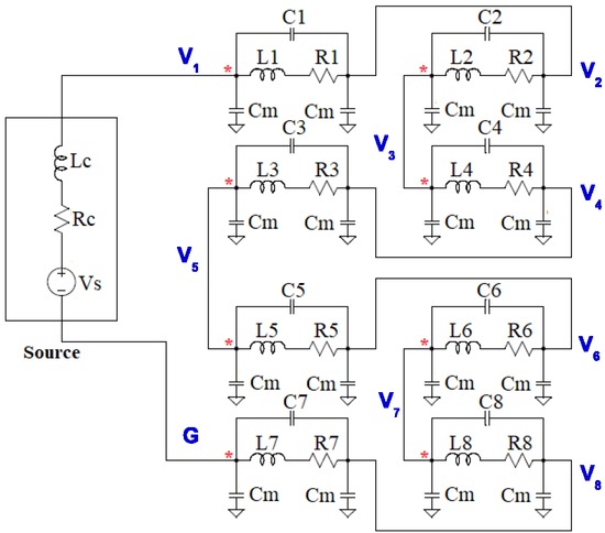
Spice equivalent circuit of a motor phase defined at the coil level.
are taken into account. The magnetic core adds common mode capacitances, which are modelled by the capacitances Cm connected between each coil terminal and ground. The voltage measurement points (v1 − v8) defined in Figure 15 are reported in the Spice equivalent circuit.
The parameters of the Spice equivalent circuit are measured with sine waves at 1MHz; Table 2 presents the self and mutual inductances relatively to coil 1 and the corresponding coil relative angular position. With the sign convention adopted (* signs in Figure 15) all the mutual inductances are negatives. The actual connections are considered in the Spice equivalent circuit in Figure 20. The self inductances of the other coils have the same value (116 μH); the mutual inductances relative to the other coils have also the values of Table 2 for identical relative angular positions.
Self and mutual inductances relative to the first coil
| L1 | M12 | M13 | M14 | |
|---|---|---|---|---|
| angle (∘) | 0 | 15 | 90 | 105 |
| (μH) | 116 | −31 | −2.6 | −2.13 |
| M15 | M16 | M17 | M18 | |
| angle (∘) | 180 | 195 | 270 | 275 |
| (μH) | −2.0 | −2.1 | −2.6 | −3.0 |
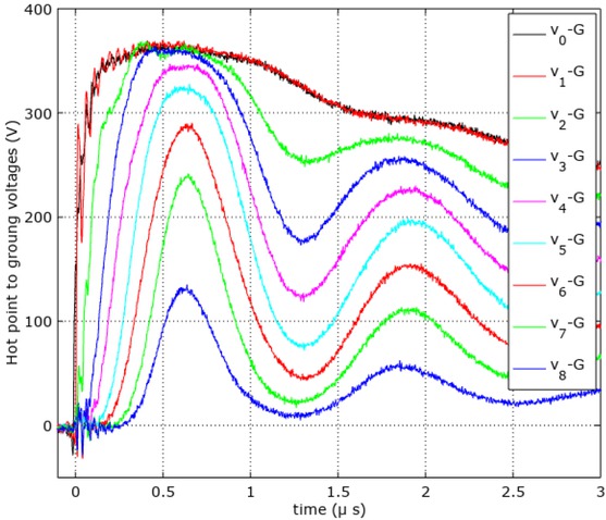
The coil resistance takes the core losses into account. The common mode capacitances are measured with an impedance analyzer the average result is Cm = 43 pF with a measurements dispersion of about 5%. The actual waveform produced by the pulse generator is taken form experimental results; the Spice source voltage vs is defined by segments joining points extracted from the experimental curve v0. Figure 21 presents the simulation results and Figure 22 compare the simulation results with the experimental ones.
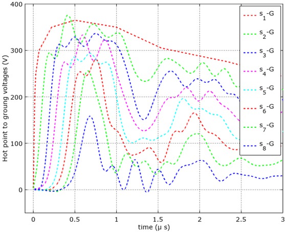
Spice simulation results for a motor phase.
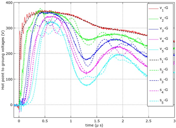
Comparison of Spice simulation results (dotted lines) and experimental ones (solid lines).
6 Discussion
Figure 22 shows a global correspondence of Spice simulation results and measurements. However, differences are be observed on the damping of each transient voltage. These differences can be interpreted considering the equivalent circuit parameter, which are measured in sine waves. The Spice equivalent circuit uses them in the time domain, which supposes constant parameters in the frequency domain. The inductances and the capacitances measured values are nearly constant in the useful frequency range (100 kHz−20MHz) but not the resistances because of skin effects in the wire and in the stator core. The Spice simulation were made with average values that do not consider all the complexity of the electromagnetic problem.
However, the Spice simulation estimates the peak voltage at the terminals of each coil for making technological pertinent choices at the design level. It shows also that the transient state, for every coils, except the first one, are about 1μs long. They are 10 times shorter for the transient inside the coil defined at the turn level. Consequently the coils 2 − 8 must withstand only 100 Vpeak for a machine phase fed by 370 V pulses. Inside these coils, the maximum turn-to-turn voltage is only 30 Vpeak, which is much under the capabilities of a ceramic coated wire operating at 500∘C, which is 200 VRMS [9]. However, a special care must be taken for the first coil that withstand 250 Vpeak during about 200 ns. The transient analysis made at the turn level (Figure 14) estimates that the turn-to-turn voltage at 30% of this value (75 V), which remains under the limits with a large safety margin.
The proposed turn arrangement for designing coils can be used for machines fed by a standard PWM inverter, when the turn-to-turn voltage must be very low.With such a turn arrangement and standard organic low temperature wire, the motor can be fed by high voltages. For HT∘ applications, the coil design compensates the poor electrical properties of the ceramic-coated wire.
7 Conclusion
The design of high temperature compact machines requires a specific approach because the machine must be fully inorganic, without any polymer. The use of magnets is also forbidden. Consequently, the only possible topology is the synchronous reluctant machine made with one rigid inorganic coils per stator tooth. These coils are made with a ceramic insulated embedded in a HT∘ cement. The ceramic insulated wire has poor electrical and mechanical properties compared to the standard organic enamelled wire. These poor properties must be compensated by a specific topology that consists in making large number of transverse layers of few turn. The proposed topology is the opposite of the classical one consisting in building coils with a small number of longitudinal layers made of many turns.
After sharing the experience for building HT∘ motor coil, an analysis of the voltage distribution inside the coil, at the turn level, is proposed. The proposed method is based on a Spice solver. The results show a good voltage distribution between turns during the fast transients following each fast fronted voltage pulse of the PWM.
Another analysis, made at the coil level, shows that the first coil withstands higher voltages than the others at the very beginning of the transient states following the PWM fronts.
The global discussion on the results of the two analyses shows that the proposed coil topology can be used for building motors, fed by standard PWM inverters and able to operate up to 500∘C inside coils.
References
[1] IEC 60172 Std., Test procedures for the determination of the temperature index of enameled and tape wrapped winding wires, 2015.Search in Google Scholar
[2] Mitsui H., Progress in japan in electrical insulation at high temperatures, IEEE Electrical Insulation Magazine, 12, 3, May 1996, 16–27.10.1109/57.509921Search in Google Scholar
[3] Schadler L. S., Nelson J. K., Calebrese C., Travelpiece A., and Schweickart D. L., High temperature breakdown strength and voltage endurance characterization of nanofilled polyamideimide, In IEEE Transactions on Dielectrics and Electrical Insulation, 19, 6, Dec. 2012, 2090–2101.10.1109/TDEI.2012.6396969Search in Google Scholar
[4] Hoang A. T., Serdyuk Y. V., and Gubanski S. M., Electrical characterization of a new enamel insulation, In IEEE Transactions on Dielectrics and Electrical Insulation, 21, 3, June 2014, 1291–1301.10.1109/TDEI.2014.6832277Search in Google Scholar
[5] Aymonino F., Lebey T., Malec D., Petit C., Saint Michel J., and Anton A., Impact of the polymerization process on the electrical behavior of different impregnation varnishes, In proceedings of IEEE Conference on Electrical Insulation and Dielectric Phenomena, Oct. 2006, 728–731.10.1109/CEIDP.2006.312035Search in Google Scholar
[6] Aymonino F., Lebey T., Malec D., Petit C., Michel J. S., Anton A., and Gimenez A., Degradation and dielectrics measurements of rotating machines insulation at high temperature (200-400∘C), In proceedings of IEEE International Conference on Solid Dielectrics (ICSD), July 2007, 130–133.10.1109/ICSD.2007.4290770Search in Google Scholar
[7] Vonroll, Mica-taped wires samicafirewall, 2015, http://www.vonroll.comSearch in Google Scholar
[8] CPG groupe Plastec, CERAFIL 500 - isolation céramique très haute temperature, Fiche technique, http://www.cables-cgp.comSearch in Google Scholar
[9] Iosif V., Roger D., Duchesne S., and Malec D., Assessment and improvements of inorganic insulation for high temperature low voltage motors, In IEEE Transactions on Dielectrics and Electrical Insulation 23, 5, October 2016, 2534–2542.10.1109/TDEI.2016.7736810Search in Google Scholar
[10] Takahashi N., Morishita M., Miyagi D., and Nakano M., Examination of magnetic properties of magnetic materials at high temperature using a ring specimen, In IEEE Transactions on Magnetics 46, 2, Feb. 2010, 548–551.10.1109/TMAG.2009.2033122Search in Google Scholar
[11] Ababsa M., Ninet O., and Velu G., High temperature characterization of electrical steels using an adapted Epstein frame, In proceedings of IEEE International Magnetics Conference (INTERMAG), April 2017.10.1109/INTMAG.2017.8007652Search in Google Scholar
[12] Cozonac D., Babicz S., Ait-Amar-Djennad S., Velu G., Cavalini A., and Wang P., Study on ceramic insulation wires for motor windings at high-temperature, In proceedings of IEEE Conference on Electrical Insulation and Dielectric Phenomena (CEIDP), Oct 2014, 172–175.10.1109/CEIDP.2014.6995757Search in Google Scholar
[13] Cozonac D., Lecointe J.-P., Duchesne S., and Velu G., Materials characterization and geometry of a high temperature induction machine, In proceedings of International Conference on Electrical Machines (ICEM), Sept 2014, 2499–2505.10.1109/ICELMACH.2014.6960538Search in Google Scholar
[14] Iosif V., Roger D., Takorabet N., Duchesne S., and Meibody-Tabar F., Technological assessments for designing machines able to work at very high internal temperatures (450–500∘C), In proceedings of International Conference on Electrical Machines (ICEM), Sep. 2016, 2682–2687.10.1109/ICELMACH.2016.7732900Search in Google Scholar
[15] Liu J., and Walmer M., Thermal stability and performance data for SmCo 2:17 high-temperature magnets on ppm focusing structures, In IEEE Transactions on Electron. Devices, 52, 5, May 2005, 899–902.10.1109/TED.2005.845868Search in Google Scholar
[16] Komeza K., Lefik M., Juszczak E. N., Roger D., Takorabet N., and Meibody-Tabar F., Analysis of the impact of the design of HT∘ machines on the cogging torque and losses in permanent magnets, In proceedings of IEEE International Conference on Power Electronics, Drives and Energy Systems (PEDES), Dec. 2016, 1–6.10.1109/PEDES.2016.7914348Search in Google Scholar
[17] Marcin L., Komeza K., Napieralska-Juszczak E., Roger D., and Napieralski P., Comparison of the reluctance laminated and solid rotor synchronous machine operating at high temperatures, In COMPEL - The international journal for computation and mathematics in electrical and electronic engineering, 2019, https://www.emerald.com/insight/content/doi/10.1108/COMPEL-10-2018-0405/full/htmlSearch in Google Scholar
[18] Roger D., Iosif V., and Duchesne S., High temperature motors: Investigations on the voltage distribution in windings at a short scale times for a PWM supply, In proceedings of IEEE International Electric Machines and Drives Conference (IEMDC), May 2017, pp. 1–7.10.1109/IEMDC.2017.8002179Search in Google Scholar
[19] Yokoi Y., Higuchi T., and Miyamoto Y., General formulation of winding factor for fractional-slot concentrated winding design, In IET Electric Power Applications 10, 4, 2016, 231–239.10.1049/iet-epa.2015.0092Search in Google Scholar
[20] Pyrhonen J., Jokien T., and Hrabovcova V., Design of rotating electrical machines. Ed. John Wiley & Sons, 2008.10.1002/9780470740095Search in Google Scholar
[21] Miller T. J. E., Electronic control of switched reluctance machines, Newnes power engineering series ed. 2001, http://www.new,espress.comSearch in Google Scholar
[22] Kant M., Les actionneurs électriques pas à pas, Traité des nouvelles technologies, Série Automatique, 1989.Search in Google Scholar
[23] Jufer M., Traité d’électricité Volume 9, Electromécanique, Presses polytechniques universitaires romandes, 2004.Search in Google Scholar
[24] Elmadah H., Roger D., and Takorabet N., Définition du prototype d’unemachine synchroréluctante haute temperature, In proceedings of Symposium de Genie Electrique (SGE), Juillet 2018.Search in Google Scholar
[25] Cotronics, Adhesifs, ciments, revetements ceramiques hautes temperatures – 100 à 3000 deg., Fiche technique, http://www.cotronics.comSearch in Google Scholar
[26] Roger D., Ninet O., and Duchesne S., Wide frequency range characterization of rotating machine stator-core laminations, In the European Physical Journal – Applied Physics (EPJ-AP) 23, 2, Aug. 2003, 103–109.10.1051/epjap:2003049Search in Google Scholar
[27] McLyman W. T., Core Selection for Transformers and Inductors: A User’s Guide to Practice and Specifications, 2018.10.1201/9781315214856Search in Google Scholar
© 2019 H. Elmadah et al., published by De Gruyter
This work is licensed under the Creative Commons Attribution 4.0 International License.
Articles in the same Issue
- Regular Articles
- Non-equilibrium Phase Transitions in 2D Small-World Networks: Competing Dynamics
- Harmonic waves solution in dual-phase-lag magneto-thermoelasticity
- Multiplicative topological indices of honeycomb derived networks
- Zagreb Polynomials and redefined Zagreb indices of nanostar dendrimers
- Solar concentrators manufacture and automation
- Idea of multi cohesive areas - foundation, current status and perspective
- Derivation method of numerous dynamics in the Special Theory of Relativity
- An application of Nwogu’s Boussinesq model to analyze the head-on collision process between hydroelastic solitary waves
- Competing Risks Model with Partially Step-Stress Accelerate Life Tests in Analyses Lifetime Chen Data under Type-II Censoring Scheme
- Group velocity mismatch at ultrashort electromagnetic pulse propagation in nonlinear metamaterials
- Investigating the impact of dissolved natural gas on the flow characteristics of multicomponent fluid in pipelines
- Analysis of impact load on tubing and shock absorption during perforating
- Energy characteristics of a nonlinear layer at resonant frequencies of wave scattering and generation
- Ion charge separation with new generation of nuclear emulsion films
- On the influence of water on fragmentation of the amino acid L-threonine
- Formulation of heat conduction and thermal conductivity of metals
- Displacement Reliability Analysis of Submerged Multi-body Structure’s Floating Body for Connection Gaps
- Deposits of iron oxides in the human globus pallidus
- Integrability, exact solutions and nonlinear dynamics of a nonisospectral integral-differential system
- Bounds for partition dimension of M-wheels
- Visual Analysis of Cylindrically Polarized Light Beams’ Focal Characteristics by Path Integral
- Analysis of repulsive central universal force field on solar and galactic dynamics
- Solitary Wave Solution of Nonlinear PDEs Arising in Mathematical Physics
- Understanding quantum mechanics: a review and synthesis in precise language
- Plane Wave Reflection in a Compressible Half Space with Initial Stress
- Evaluation of the realism of a full-color reflection H2 analog hologram recorded on ultra-fine-grain silver-halide material
- Graph cutting and its application to biological data
- Time fractional modified KdV-type equations: Lie symmetries, exact solutions and conservation laws
- Exact solutions of equal-width equation and its conservation laws
- MHD and Slip Effect on Two-immiscible Third Grade Fluid on Thin Film Flow over a Vertical Moving Belt
- Vibration Analysis of a Three-Layered FGM Cylindrical Shell Including the Effect Of Ring Support
- Hybrid censoring samples in assessment the lifetime performance index of Chen distributed products
- Study on the law of coal resistivity variation in the process of gas adsorption/desorption
- Mapping of Lineament Structures from Aeromagnetic and Landsat Data Over Ankpa Area of Lower Benue Trough, Nigeria
- Beta Generalized Exponentiated Frechet Distribution with Applications
- INS/gravity gradient aided navigation based on gravitation field particle filter
- Electrodynamics in Euclidean Space Time Geometries
- Dynamics and Wear Analysis of Hydraulic Turbines in Solid-liquid Two-phase Flow
- On Numerical Solution Of The Time Fractional Advection-Diffusion Equation Involving Atangana-Baleanu-Caputo Derivative
- New Complex Solutions to the Nonlinear Electrical Transmission Line Model
- The effects of quantum spectrum of 4 + n-dimensional water around a DNA on pure water in four dimensional universe
- Quantum Phase Estimation Algorithm for Finding Polynomial Roots
- Vibration Equation of Fractional Order Describing Viscoelasticity and Viscous Inertia
- The Errors Recognition and Compensation for the Numerical Control Machine Tools Based on Laser Testing Technology
- Evaluation and Decision Making of Organization Quality Specific Immunity Based on MGDM-IPLAO Method
- Key Frame Extraction of Multi-Resolution Remote Sensing Images Under Quality Constraint
- Influences of Contact Force towards Dressing Contiguous Sense of Linen Clothing
- Modeling and optimization of urban rail transit scheduling with adaptive fruit fly optimization algorithm
- The pseudo-limit problem existing in electromagnetic radiation transmission and its mathematical physics principle analysis
- Chaos synchronization of fractional–order discrete–time systems with different dimensions using two scaling matrices
- Stress Characteristics and Overload Failure Analysis of Cemented Sand and Gravel Dam in Naheng Reservoir
- A Big Data Analysis Method Based on Modified Collaborative Filtering Recommendation Algorithms
- Semi-supervised Classification Based Mixed Sampling for Imbalanced Data
- The Influence of Trading Volume, Market Trend, and Monetary Policy on Characteristics of the Chinese Stock Exchange: An Econophysics Perspective
- Estimation of sand water content using GPR combined time-frequency analysis in the Ordos Basin, China
- Special Issue Applications of Nonlinear Dynamics
- Discrete approximate iterative method for fuzzy investment portfolio based on transaction cost threshold constraint
- Multi-objective performance optimization of ORC cycle based on improved ant colony algorithm
- Information retrieval algorithm of industrial cluster based on vector space
- Parametric model updating with frequency and MAC combined objective function of port crane structure based on operational modal analysis
- Evacuation simulation of different flow ratios in low-density state
- A pointer location algorithm for computer visionbased automatic reading recognition of pointer gauges
- A cloud computing separation model based on information flow
- Optimizing model and algorithm for railway freight loading problem
- Denoising data acquisition algorithm for array pixelated CdZnTe nuclear detector
- Radiation effects of nuclear physics rays on hepatoma cells
- Special issue: XXVth Symposium on Electromagnetic Phenomena in Nonlinear Circuits (EPNC2018)
- A study on numerical integration methods for rendering atmospheric scattering phenomenon
- Wave propagation time optimization for geodesic distances calculation using the Heat Method
- Analysis of electricity generation efficiency in photovoltaic building systems made of HIT-IBC cells for multi-family residential buildings
- A structural quality evaluation model for three-dimensional simulations
- WiFi Electromagnetic Field Modelling for Indoor Localization
- Modeling Human Pupil Dilation to Decouple the Pupillary Light Reflex
- Principal Component Analysis based on data characteristics for dimensionality reduction of ECG recordings in arrhythmia classification
- Blinking Extraction in Eye gaze System for Stereoscopy Movies
- Optimization of screen-space directional occlusion algorithms
- Heuristic based real-time hybrid rendering with the use of rasterization and ray tracing method
- Review of muscle modelling methods from the point of view of motion biomechanics with particular emphasis on the shoulder
- The use of segmented-shifted grain-oriented sheets in magnetic circuits of small AC motors
- High Temperature Permanent Magnet Synchronous Machine Analysis of Thermal Field
- Inverse approach for concentrated winding surface permanent magnet synchronous machines noiseless design
- An enameled wire with a semi-conductive layer: A solution for a better distibution of the voltage stresses in motor windings
- High temperature machines: topologies and preliminary design
- Aging monitoring of electrical machines using winding high frequency equivalent circuits
- Design of inorganic coils for high temperature electrical machines
- A New Concept for Deeper Integration of Converters and Drives in Electrical Machines: Simulation and Experimental Investigations
- Special Issue on Energetic Materials and Processes
- Investigations into the mechanisms of electrohydrodynamic instability in free surface electrospinning
- Effect of Pressure Distribution on the Energy Dissipation of Lap Joints under Equal Pre-tension Force
- Research on microstructure and forming mechanism of TiC/1Cr12Ni3Mo2V composite based on laser solid forming
- Crystallization of Nano-TiO2 Films based on Glass Fiber Fabric Substrate and Its Impact on Catalytic Performance
- Effect of Adding Rare Earth Elements Er and Gd on the Corrosion Residual Strength of Magnesium Alloy
- Closed-die Forging Technology and Numerical Simulation of Aluminum Alloy Connecting Rod
- Numerical Simulation and Experimental Research on Material Parameters Solution and Shape Control of Sandwich Panels with Aluminum Honeycomb
- Research and Analysis of the Effect of Heat Treatment on Damping Properties of Ductile Iron
- Effect of austenitising heat treatment on microstructure and properties of a nitrogen bearing martensitic stainless steel
- Special Issue on Fundamental Physics of Thermal Transports and Energy Conversions
- Numerical simulation of welding distortions in large structures with a simplified engineering approach
- Investigation on the effect of electrode tip on formation of metal droplets and temperature profile in a vibrating electrode electroslag remelting process
- Effect of North Wall Materials on the Thermal Environment in Chinese Solar Greenhouse (Part A: Experimental Researches)
- Three-dimensional optimal design of a cooled turbine considering the coolant-requirement change
- Theoretical analysis of particle size re-distribution due to Ostwald ripening in the fuel cell catalyst layer
- Effect of phase change materials on heat dissipation of a multiple heat source system
- Wetting properties and performance of modified composite collectors in a membrane-based wet electrostatic precipitator
- Implementation of the Semi Empirical Kinetic Soot Model Within Chemistry Tabulation Framework for Efficient Emissions Predictions in Diesel Engines
- Comparison and analyses of two thermal performance evaluation models for a public building
- A Novel Evaluation Method For Particle Deposition Measurement
- Effect of the two-phase hybrid mode of effervescent atomizer on the atomization characteristics
- Erratum
- Integrability analysis of the partial differential equation describing the classical bond-pricing model of mathematical finance
- Erratum to: Energy converting layers for thin-film flexible photovoltaic structures