
Diagnostics and Identification of Injection Duration of Common Rail Diesel Injectors
-
Tomi R. Krogerus
 and
Kalevi J. Huhtala
and
Kalevi J. Huhtala

Abstract
In this paper, we study the diagnostics and identification of injection duration of common rail (CR) diesel pilot injectors of dual-fuel engines. In these pilot injectors, the injected volume is small and the repeatability of the injections and identification of the drifts of the injectors are important factors, which need to be taken into account in achieving good repeatability (shot-to-shot with every cylinder) and therefore a well-balanced engine and reduced overall wear. A diagnostics method based on analysis of CR pressure signal with experimental verification results is presented. Using the developed method, the relative duration of injection events can be identified. In the method, the pressure signal during the injection is first extracted after the control of each injection event. After that, the signal is normalized and filtered. Then a derivative of the filtered signal is calculated. Change in the derivative of the filtered signal larger than a predefined threshold indicates an injection event which can be detected and its relative duration can be identified. The efficacy of the proposed diagnostics method is presented with the experimental results, which show that the developed method detects drifts in injection duration and the magnitude of drift. According to the result, ≥ 10 μs change (2%, 500 μs) in injection time can be identified.
1 Introduction
Diesel engines are widely used due to their high reliability, high thermal efficiency, fuel availability, and low consumption. They are used to generate power, e.g. in passenger cars, ships, power plants, marine offshore platforms, and mining and construction machines. The engine is at the heart of these applications, so keeping it in good working condition is vital. Recent technical and computational advances and environmental legislation have stimulated the development of more efficient and robust techniques for the diagnostics of diesel engines. Regulations concerning exhaust-gas emissions have also influenced the development of gas engines. To maintain a high compression ratio of the compression–ignition engine for higher engine efficiency, it is necessary to use a dual-fuel system.
The diesel fuel injection of an engine plays an important role in the development of combustion in the engine cylinder. Arguably, the most influential component of the diesel engine is the fuel injection equipment; even minor faults can cause a major loss of efficiency of the combustion and an increase in engine emissions and noise [1]. In order to meet increasingly stringent emissions regulations, and to satisfy growing demands in relation to economy and engine performance, precision injection timing and exact fuel quantity dosing have become key elements over the entire operational life of the engine. These goals are seriously affected by fuel quality and the contained particles, which often lead to more or less unpredictable wear of the parts.
Diagnostics of CR system and especially the diagnostics of CR injectors have been widely studied e.g. [2, 3, 4, 5, 6, 7, 8, 9]. Krogerus et al. [10] have presented a survey of the analysis, modelling, and diagnostics of diesel fuel injection systems. In this publication, typical diesel fuel injection systems and their common faults are presented. The most relevant state of the art research articles on diagnostics techniques and measured signals describing the behaviour of the system are reviewed and the results and findings discussed. The increasing demand and effect of legislation related to diagnostics, especially on-board diagnostics (OBD), are discussed with reference to the future development of this field.
Estimation of injected fuel amount has been studied in [2, 3, 4, 5]. Hoffmann et al. [2] developed a model-based injection rate estimator, which takes into account the change in the injection behaviour due to wear and aging effects within the injector’s nozzle. Satkoski et al. [3, 4] summarize the development of a physics-based fuel flow estimator. Available measurements of piezo stack voltage and rail-to-injector line pressure are used for dynamic state estimation. Estimator results are compared against both open-loop simulation and experimental data for a variety of profiles at different rail pressures, and show improvement, particularly, for more complex multi-pulse profiles. Bauer et al. [5] have developed a model for online estimation of fuel property parameters with the Unscented Kalman Filtering (UKF) method. The model was tested with data from a simulation model and a fuel injection system test rig that was specifically constructed for this purpose. It was found that it is possible to estimate the parameters with negligible bias and that the method is generally suitable.
Using the rail pressure signal for the diagnostics of injector events has been previously studied in [6, 7, 8, 9]. Akiyama et al. [6] investigated a method to compensate the difference between an actual amount of injected fuel and a target one. In order to compensate the difference, the influence of pressure wave on fuel amount injected is investigated and injection period will be corrected is realized in an actual engine control system. Meanwhile, pressure wave propagation in common-rail was studied. Isermann et al. [7] developed a model-based fault detection module for diesel CR injection systems. One of the simulated faults was a changed fuel volume through one of the injectors and was realized by changing the desired injection quantity. Payri et al. [8] studied injection diagnosis through diesel CR pressure measurements, where the objective was to design an algorithm for the isolation of the injection events. Marker et al. [9] studied the diagnostics of large light fuel oil (LFO) diesel engines where the main diesel injections were investigated, and the beginning and duration of injection were determined.
This research is dedicated to the diagnostics of the CR diesel pilot injectors of dual-fuel large industrial engines. The aim is to diagnose, meaning here to detect injection events and identify the relative duration of them based on analysing the pressure signal of the CR in the case of the injection duration being changed to simulate, e.g. the wear of injectors. The main difference between the proposed diagnostic method and the methods presented in literature is that the former is able to detect and identify the duration of pilot injections with high precision. The injected fuel volume of diesel pilot injectors is extremely small compared to main injections, which most publications are dealing with.
The rest of this paper is organized as follows. The next section presents the utilized CR test system. Then the diagnostics method is introduced followed by the experiments and the analysis results. Finally, the last section summarizes our conclusions and discusses future development.
2 Methods
2.1 Experimental setup
The CR rail test system, a commercial CR system (passenger car) presented in Figure 1, was utilized to acquire data for studying and developing the diagnostics methods of CR systems. A second generation pilot diesel injector of a dual-fuel engine was installed in this test system. For this system, a custom-made electronic control unit (ECU) controlling the rail pressure of the CR system and the studied injector was manufactured, which made possible to freely adjust injection duration, number of injections, time between injections, control currents (boost and hold), pressure level, etc. Castrol’s diesel injector calibration oil 4113 [11] was used in the CR system.
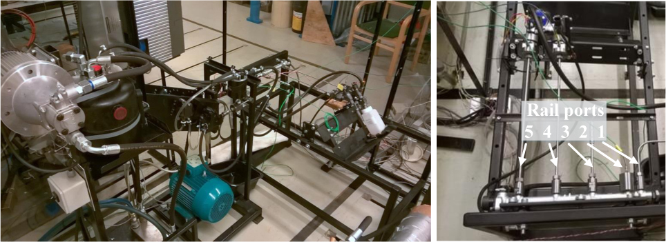
CR test system at Tampere University of Technology (TUT). Port 1 (from the right): supply line, Port 2: rail pressure (Kistler), Port 3: temperature (K Type thermocouple), Port 4: injector (not studied) and Port 5: studied injector.
The pressures of the CR system are measured using high dynamic Kistler pressure sensors (Type: 4067 A 2000) and an accurate but lower dynamic Trafag pressure sensor (EPN CR 20 A 1600 bar). A Bosch pressure sensor (original CR system sensor) is used for controlling the rail pressure level, and it is connected to the ECU. The studied injector includes a needle lift sensor (Micro-Epsilon eddyNCDT 3010), which enables the detection of needle opening and closing events. The control current of the injector and pressure regulator were measured using LEM current transducer modules located in the ECU. The temperatures were measured from the tank using a Pt100 sensor and from the rail using a K Type thermocouple. The diagnostic method presented in this paper is based on data from the high dynamic pressure sensor (Kistler). All the measurements were collected using a National Instruments data acquisition card type PCI 6125 using LabVIEW software.
The analysed rail pressure data (Kistler) and the other rail pressure signal (Trafag), the injection current and the needle lift were sampled at 250 kHz frequency (sampling period 4 μs). The Kistler pressure sensor is suitable for collecting static and high dynamic pressures, while the Trafag pressure sensor is meant for measuring static measurements. Therefore, a Kistler sensor was utilized for analysis purposes. Due to the limitations of the used acquisition card (max. 1 MHz), injector input pressure and temperatures were not measured. Temperatures were collected manually. Original rail pressure and pressure regulator control current were used in ECU but were not recorded.
2.2 Diagnostics method
The developed diagnostics method for the detection of injection events and for identification of injection duration is based on analysed rail pressure signal and its drop after the injection event. Figure 2 presents a typical pressure drop with following oscillations due to injection and corresponding control current of an injector. Besides these, an example of six injections corresponding to approx. 720 degree crank angle (oCA) of an engine is presented. It should be noted here that approximately 10 ms of data is collected after each injection (see Figure 2 for the lowest figure) while using the control current signal to trigger the data acquisition.

Example of injector current, rail pressure after single injection and six injections (720 oCA) with 16ms time between injections.
In the method, the pressure signal during the injection is first extracted after the control of each injection event. After that, the signal is normalized, offset is reset and the signal is filtered. Resetting the offset means removing pressure level difference between single injections at the same moment as the control of an injector is activated. This is due to the phase of the axial piston pump not being the same in each data set because the series of injections is started manually. In real engines, this has been taken into account and offset resetting is not needed. The filtering of pressure oscillation is needed to remove the oscillation of the pressure signal as much as possible. A low pass IIR filter of 10th order with cut-off frequency of 450 Hz was utilized to attenuate the pressure oscillations. In the case of a real engine and multiple injectors, a separate cutoff frequency for each injector is needed. After filtering, a derivative of the filtered signal is calculated. Change in the derivative of the filtered signal smaller than a predefined threshold indicates an injection event and the start of injection. Similarly, after the detected start of injection, change in the derivative of the filtered signal larger than this threshold indicates the end of injection. Using the corresponding identified relative start time and end time of injection, the relative duration of injection can be calculated. The threshold is selected so that it is clearly smaller than the remaining rail pressure oscillation after the injection event and large enough to include all the injection events. The general sigma rule applied to the remaining rail pressure oscillation, i.e. multiple standard deviation added to the mean of the distribution will give practical threshold.
3 Results
The developed method was verified using the CR test system of Tampere University of Technology with one injector (see: Figure 1). In the experiments, the system was first warmed to 37 degrees (°C) by driving test cycles with high pressure while a thermostat controlled the cooling system maintaining the temperature at 37 ± 1°C. Injection times of 500 μs, 505 μs, 510 μs, 525 μs, 550 μs, 625 μs and 750 μs (the increase of 1, 2, 5, 10, 25 and 50 % in this injection time) were used to simulate a drift of injection duration. The time between injections was 16 ms (approximately 6 injections per 720 oCA). The pressure level was 1400 bar. One hundred injections per different injection time were used, so altogether 700 injection events were analysed. The sampling frequency of the measurements was 250 kHz. This high sampling frequency is not needed, but it does need to be ≥ 10 kHz, and preferably closer to 30 kHz. Smaller sampling frequencies decrease the resolution of the identified relative duration of injection time.
In the analysis, the pressure signal during the injection is first extracted (see Figure 3a). After that, the signal is normalized and offset is reset (see Figure 3b). After removing the offset, the signal is filtered and a derivative of the filtered signal is calculated (see Figure 3c). Figure 3d presents the final result which is the identified relative injection duration. In Figure 3d, the mean values of 100 injections for different injection times are presented. Here it can be noticed that a ≥ 2% change (= 10 μs) in injection time can be identified. It is possible to fit a curve to these values and calculate the real injection duration.
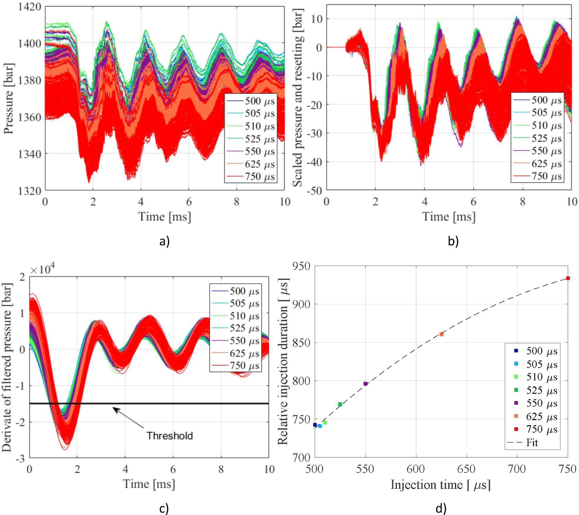
a) extracted, b) normalized and offset reset, c) derivate of filtered pressure signals, d) identified relative injection durations.
4 Discussion and conclusions
The diagnostics and identification of relative injection duration of the pilot diesel injector of a dual-fuel large industrial engine were presented in this paper. A method based on the analysis of CR rail pressure was presented with experimental results using a single injector. Injection times of 500 μs – 750 μs (an increase of 1, 2, 5, 10, 25 and 50 % in the injection time) were used to simulate a drift of injection duration. The changed injection time was detected and its relative duration was calculated from the rail pressure signal. The results show that the developed method detects drifts of injection duration and identifies the magnitude of drift, which could be used for adaptive control of injection duration, i.e. adjusting the cylinder specific injection duration so that finally the injected fuel volume is the same as the original. According to the result, a ≥ 10 μs change (2%, 500 μs) in injection time can be properly identified.
Data quality issues are a challenge for the industrialization of this method, and need special attention. This refers to the robustness of the rail pressure sensor (break down, offset drifts, etc.) and the high sampling frequencies of sensor signals (> 10 kHz). In this research, the implementation of embedded solutions was not studied. Thus, the implementation of filtering algorithms for embedded solution needs further research, and furthermore additional testing and verification of this method with real engine data is still needed to fully validate the method.
Acknowledgement
The authors gratefully acknowledge the support of this work by DIMECC’s (The Strategic Centres for Science, Technology and Innovation) S-STEP Program, Smart Technologies for Lifecycle Performance.
References
[1] Gill J., Reuben R., Steel J., Scaife M., and Asquith J., A Study of Small HSDI Diesel Engine Fuel Injection Equipment Faults Using Acoustic Emission, Journal of Acoustic Emission, 2000, 18, 211–216Search in Google Scholar
[2] Hoffmann O., Han S. and Rixen, D., Common Rail Diesel Injectors with Nozzle Wear: Modeling and State Estimation, SAE Technical Paper 2017-01-0543, 201710.4271/2017-01-0543Search in Google Scholar
[3] Satkoski C., Ruikar N., Biggs S. and Shaver G., Cycle-to-cycle Estimation and Control of Multiple Pulse Profiles for a Piezoelectric Fuel Injector, 2011 American Control Conference on O’Farrell Street, San Francisco, CA, USA, June 29 - July 01, 2011, 965-97210.1109/ACC.2011.5990758Search in Google Scholar
[4] Satkoski C. and Shaver G., Piezoelectric Fuel Injection: Pulse-to-Pulse Coupling and Flow Rate Estimation, IEEE/ASME Transaction on Mechatronics, 2011, 16, 627-64210.1109/TMECH.2010.2048334Search in Google Scholar
[5] Baur R., Zhao Q., Blath J., Kallage F., Schultalbers M. and Bohn C., Estimation of Fuel Properties in a Common Rail Injection System by Unscented Kalman Filtering, 2014 IEEE Conference on Control Applications (CCA), Antibes, France, October 8-10, 2014, 2040-204710.1109/CCA.2014.6981603Search in Google Scholar
[6] Akiyama H., Yuasa H., Kato A., Saiki T. et al., Precise Fuel Control of Diesel Common-Rail System by Using OFEM, SAE Technical Paper 2010-01-0876, 201010.4271/2010-01-0876Search in Google Scholar
[7] Isermann R., Clever S., Model-Based Fault Detection and Diagnosis for Common-Rail Injections Systems, MTZ, 2010, 22, 344–349Search in Google Scholar
[8] Payri F., Luján J., Guardiola C., Rizzoni G., Injection Diagnosis through Common-Rail Pressure Measurement, Proceedings of the Mechanical Engineering, Part D: Journal of Automobile Engineering, 2006, 220, 347-35710.1243/09544070JAUTO34Search in Google Scholar
[9] Marker J., Willmann M., Potential of INSITU Closed-Loop Control of Fuel Injection in Large LFO Engines, Proceedings of 15th Conference of the Working Process of the Internal Combustion Engine, Graz, Austria, September 24-25, 2015, 393-402Search in Google Scholar
[10] Krogerus T., Hyvönen M., Huhtala K., A Survey of Analysis, Modeling, and Diagnostics of Diesel Fuel Injection Systems, Journal of Engineering for Gas Turbines and Power: Transaction of the ASME, 2016, 138, 1-1110.1115/1.4032417Search in Google Scholar
[11] Castrol Limited, Castrol diesel injector calibration oil 4113, Accessed April 27 http://msdspds.castrol.com/bpglis/FusionPDS.nsf/Files/2AF8D13D25BFB750802577E0005BB19F/$File/BPXE-8BGMVA_0.pdfSearch in Google Scholar
© 2018 Tomi R. Krogerus and Kalevi J. Huhtala
This work is licensed under the Creative Commons Attribution-NonCommercial-NoDerivatives 4.0 License.
Articles in the same Issue
- Regular Article
- Real-scale comparison between simple and composite raw sewage sampling
- 10.1515/eng-2018-0017
- The risks associated with falling parts of glazed facades in case of fire
- Implementation of high speed machining in thin-walled aircraft integral elements
- Evaluating structural crashworthiness and progressive failure of double hull tanker under accidental grounding: bottom raking case
- Influence of Silica (SiO2) Loading on the Thermal and Swelling Properties of Hydrogenated-Nitrile-Butadiene-Rubber/Silica (HNBR/Silica) Composites
- Statistical Variations and New Correlation Models to Predict the Mechanical Behavior and Ultimate Shear Strength of Gypsum Rock
- Analytic approximate solutions to the chemically reactive solute transfer problem with partial slip in the flow of a viscous fluid over an exponentially stretching sheet with suction/blowing
- Thermo-mechanical behavior simulation coupled with the hydrostatic-pressure-dependent grain-scale fission gas swelling calculation for a monolithic UMo fuel plate under heterogeneous neutron irradiation
- Optimal Auxiliary Functions Method for viscous flow due to a stretching surface with partial slip
- Vibrations Analysis of Rectangular Plates with Clamped Corners
- Evaluating Lean Performance of Indian Small and Medium Sized Enterprises in Automotive Sector
- FPGA–implementation of PID-controller by differential evolution optimization
- Thermal properties and morphology of polypropylene based on exfoliated graphite nanoplatelets/nanomagnesium oxide
- A computer-based renewable resource management system for a construction company
- Hygrothermal Aging of Amine Epoxy: Reversible Static and Fatigue Properties
- The selected roof covering technologies in the aspect of their life cycle costs
- Influence of insulated glass units thickness and weight reduction on their functional properties
- Structural analysis of conditions determining the selection of construction technology for structures in the centres of urban agglomerations
- Selection of the optimal solution of acoustic screens in a graphical interpretation of biplot and radar charts method
- Subsidy Risk Related to Construction Projects: Seeking Causes
- Multidimensional sensitivity study of the fuzzy risk assessment module in the life cycle of building objects
- Planning repetitive construction projects considering technological constraints
- Identification of risk investment using the risk matrix on railway facilities
- Comparison of energy parameters of a centrifugal pump with a multi-piped impeller in cooperation either with an annular channel and a spiral channel
- Influence of the contractor’s payment method on the economic effectiveness of the construction project from the contractor’s point of view
- Special Issue Automation in Finland
- Diagnostics and Identification of Injection Duration of Common Rail Diesel Injectors
- An advanced teaching scheme for integrating problem-based learning in control education
- A survey of telerobotic surface finishing
- Wireless Light-Weight IEC 61850 Based Loss of Mains Protection for Smart Grid
- Smart Adaptive Big Data Analysis with Advanced Deep Learning
- Topical Issue Desktop Grids for High Performance Computing
- A Bitslice Implementation of Anderson’s Attack on A5/1
- Efficient Redundancy Techniques in Cloud and Desktop Grid Systems using MAP/G/c-type Queues
- Templet Web: the use of volunteer computing approach in PaaS-style cloud
- Using virtualization to protect the proprietary material science applications in volunteer computing
- Parallel Processing of Images in Mobile Devices using BOINC
- “XANSONS for COD”: a new small BOINC project in crystallography
- Special Issue on Sustainable Energy, Engineering, Materials and Environment
- An experimental study on premixed CNG/H2/CO2 mixture flames
- Tidal current energy potential of Nalón river estuary assessment using a high precision flow model
- Special Spring Issue 2017
- Context Analysis of Customer Requests using a Hybrid Adaptive Neuro Fuzzy Inference System and Hidden Markov Models in the Natural Language Call Routing Problem
- Special Issue on Non-ferrous metals and minerals
- Study of strength properties of semi-finished products from economically alloyed high-strength aluminium-scandium alloys for application in automobile transport and shipbuilding
- Use of Humic Sorbent from Sapropel for Extraction of Palladium Ions from Chloride Solutions
- Topical Issue on Mathematical Modelling in Applied Sciences, II
- Numerical simulation of two-phase filtration in the near well bore zone
- Calculation of 3D Coordinates of a Point on the Basis of a Stereoscopic System
- The model of encryption algorithm based on non-positional polynomial notations and constructed on an SP-network
- A computational algorithm and the method of determining the temperature field along the length of the rod of variable cross section
- ICEUBI2017 - International Congress on Engineering-A Vision for the Future
- Use of condensed water from air conditioning systems
- Development of a 4 stroke spark ignition opposed piston engine
- Development of a Coreless Permanent Magnet Synchronous Motor for a Battery Electric Shell Eco Marathon Prototype Vehicle
- Removal of Cr, Cu and Zn from liquid effluents using the fine component of granitic residual soils
- A fuzzy reasoning approach to assess innovation risk in ecosystems
- Special Issue SEALCONF 2018
- Brush seal with thermo-regulating bimetal elements
- The CFD simulation of the flow structure in the sewage pump
- The investigation of the cavitation processes in the radial labyrinth pump
- Testing of the gaskets at liquid nitrogen and ambient temperature
- Probabilistic Approach to Determination of Dynamic Characteristics of Automatic Balancing Device
- The design method of rubber-metallic expansion joint
- The Specific Features of High-Velocity Magnetic Fluid Sealing Complexes
- Effect of contact pressure and sliding speed on the friction of polyurethane elastomer (EPUR) during sliding on steel under water wetting conditions
- Special Issue on Advance Material
- Effect of thermo-mechanical parameters on the mechanical properties of Eurofer97 steel for nuclear applications
- Failure prediction of axi-symmetric cup in deep drawing and expansion processes
- Characterization of cement composites based on recycled cellulosic waste paper fibres
- Innovative Soft Magnetic Composite Materials: Evaluation of magnetic and mechanical properties
- Statistical modelling of recrystallization and grain growth phenomena in stainless steels: effect of initial grain size distribution
- Annealing effect on microstructure and mechanical properties of Cu-Al alloy subjected to Cryo-ECAP
- Influence of heat treatment on corrosion resistance of Mg-Al-Zn alloy processed by severe plastic deformation
- The mechanical properties of OFHC copper and CuCrZr alloys after asymmetric rolling at ambient and cryogenic temperatures