Comparison of energy parameters of a centrifugal pump with a multi-piped impeller in cooperation either with an annular channel and a spiral channel
-
 and
and

Abstract
The article presents results of numerical analyzes, which raise a subject of influence of the cooperation the multi-piped impeller with a rationalized flow geometry of annular casing and volute casing for liquid flow through centrifugal pump and their operating parameters in the extremely low specific speed nq<10. The multi-piped impeller (patented by authors) is a major alternative to classic vane impellers. The stator type is responsible for the conversion of the kinetic energy of the liquid by the impeller outlet into potential energy, which determines the overall efficiency of the pump. Also, the article presents qualitative and quantitative verification of results obtained by computer modeling and an attempt to estimate their accuracy. The article focuses mainly on the comparison of the performance parameters of the pump with a multi-piped impeller in cooperation with two stator types with a rationalized flow geometry. Both outlet elements were tested in various configurations of constructional features. The complexity of the construction of the stator can significantly affect the manufacturing costs of pump unit.
Knowledge concerning construction of hydraulic elements of centrifugal pumps working in the range of parameters corresponding specific speed (nq<10) is insufficient. As shown in the paper, the annular type casing model pump cooperating with a multi-piped impeller, designed in accordance with literature, reached far poorer operating parameters than the rational annular construction in a configuration with the same impeller.
Nomenclature
βcw start angle of a spiral volute tongue [deg]
ϵ convergence criterion
ηc total efficiency
ηh hydraulic efficiency
ηm mechanical efficiency
ηv volumetric efficiency
ω angular velocity [rad/s]
ρ density [kg/m3]
b3kk width of an annular casing [mm]
b3sp width of volute casing [mm]
b3 width of a volute casing inlet [mm]
d4 outer diameter of a stator [mm]
g acceleration due to gravity [m/s2]
Hu total pump head [m]
Mt total moment on the impeller rotating surfaces [Nm]
n rotational speed [rpm]
nq kinematic specific speed (nq=n) [rpm]
p ambient pressure [Pa]
pcin total pressure in an impeller inlet section [Pa]
pcout total pressure in a pump outlet section [Pa]
P h hydraulic power [W]
Pw power on a pump shaft [W]
Q flow rate [m3/ h]
Re Reynolds number
ts time step [s]
ux velocity in direction X [m/s]
va average fluid velocity in stator [m/s]
1 Introduction
In order to improve the design of stators of centrifugal pumps, a better understanding of the flow of such machines is required. This paper deals with the experimental and theoretical study of the flow in the two types of stators (annular casing and volute casing) of a low specific speed centrifugal pump. Similar research have been performed in article [1] but for classical blade impellers. The role of the outlet stator becomes particularly important when considering innovational and untypical constructions of the centrifugal impeller. An example of such a construction is a multi-piped impeller whose name (proposed by the authors) and conception ofworking has been developed and patented [2] during development with hole impeller (Figure 1a) – hole impeller have been known, researched and used for a long time [3, 4]. The multi-piped impeller (Figure 1b) is completely new idea of design centrifugal pump rotors. This construction works in a range of ultra low specific speed nq < 10 (def. nq according [3, 4]). It uses the classical centrifugal liquid flow through the internal channels of the impeller as well as the additional external flow associated with the phenomenon of flow around the pipes to transfer energy.
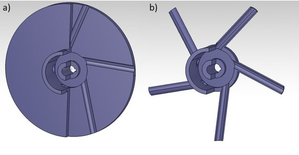
Comparison of geometry of rotors of special centrifugal pumps: a) hole impeller, b) multi-piped impeller
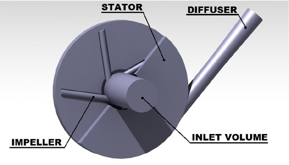
The centrifugal pump from a hydraulic point of view consist of two main elements: an impeller responsible for changing mechanical energy of the motor to hydraulic energy and the stator which the following functions:
it converts kinetic energy of the liquid after the rotor outlet into potential energy. The efficiency of this alteration largely determines performance of the whole pump.
It collects liquid flowing out of the impeller and carries it to the outlet of the pump or to the inlet of the next stage rotor in multistage pumps.
Flow area of that element determines the BEP (Best Efficiency Point) location on the pump characteristic.
Centrifugal pump with multi-piped impeller cooperating with a proper choice and design of the stator is an interesting alternative to classical blade impellers both from operating parameters and costs of manufacturing (especially working in ultra low specific speed nq < 10). This pumps could be used in chemical industry (pumping corrosive liquids), petrochemical industry (pumping gasoline or diesel), automation systems (micro-pumps for hydraulic cylinders) or firefighting.
In the literature [3] the author claims that for pumps with low and extremely low specific speed it is better to apply a channel of a constant and simple cross-section than a different stator type, since together with the decrease of nq the difference in efficiency between an annular channel and volute casing diminishes, so that at specific speed nq < 12 the annular channel could represent higher efficiency. It is important, that, to make such a channel with the highest surface quality which guarantees losses reduction at the process of momentum exchange. This claim was verified by authors later in the article.
In order to evaluate the concept of using a multi-piped impeller in centrifugal pumps, comparative experimental investigations of hole impeller and multi-piped rotors were conducted [5]. In addition, preliminary CFD analysis were conducted to identify the flow phenomena associated with the flow around the pipes in the rotor. Based on many research performed by authors – both experimental research prepared at the laboratory rig and a numerical analysis – which raised issues of hole impellers and multi-piped impellers, could be conclude that second rotor generates 30% total head pump Hu more than hole rotor (the same amount and width b2 of flow channels was maintained in both construction). As a result, it is possible to optimize the geometry of the impeller as for example by reduction in outer diameter d2 of the impeller for the same energy parameters as in the hole rotor. (total head pump Hu and pump capacity Q).
The essence of the multi-piped impeller work is related to phenomena occurred during the external liquid flow around outer surface of flow channels of the impeller. No information was found in the literature, apparently, this topic has not been tested so far. At the very beginning, authors of article thought of two different theories (both based on the liquid circulation around the profile – in this case cylindrical channel). The first is related to the generated resistance force in the concept of the aerodynamic flow of the airfoil. It is more true for propeller pumps. The second idea – more probably – is based on the theory of vortex pumps with lateral channel accordance with literature [6]. The fluid flow around the impeller pipes (flow channels) generates strong vortex of liquid. It is visible through vortex paths behind the flow channels – similar to Karman vortex streets presented in Figure 2 (for average fluid velocity va = 6 m/ s in stator of a base model pump, Re was about 59·103).
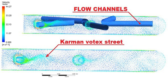
Vortex paths associated with the phenomenon of external flow around the pipes of impeller
This study aims at modelling a flow in a pump with an annular channel and a spiral channel (in cooperate with multi-piped impeller) using CFD and verifying a numerical model against experimental data. The verified numerical model will be used for identifying the flow phenomena in such a construction and for further research aimed at determining the impact of geometrical features of such a stator on the operating parameters and efficiency of the process of transferring liquid energy.
2 Test rig and object of research
A basic object of the research is a stator of model pump in cooperation with multi-piped impeller with rectilinear pipes (flow channels) inclined at an angle of 60∘ to the rotor axis. The geometry of impeller was presented in Figure 1b (dimensionswere presented in article [5]). Base type of stator used in construction of model pump of the test rig is annular casing whose dimensions was presented in Figure 3.
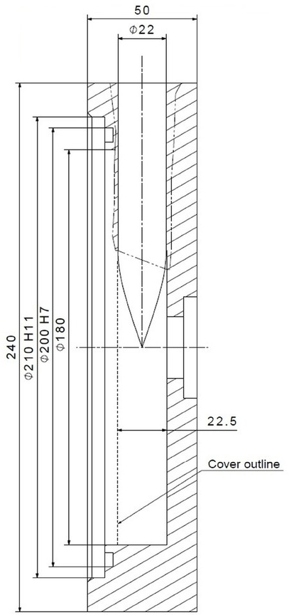
Dimensions of base annular casing of model pump
In order to verify the results of whole numerical calculations experimental tests on a test rig (Figure 4a) were scheduled and conducted. Measuring instruments applied to measure proper physical qualities on the test rig were included in Table 1 together with the range and accuracy class. More details concerning the test rig as well methodology of measurements can be found in the publication of the authors [5]. The main element of the test rig was a module pump (Figure 4b) designed in a way which would allow a fast exchange of flow elements (impellers, stators). The measurements at the test rig were totally automated, in compliance with the standard [7], with the use of a computer and a dedicated control software. The measurement was conducted from a complete opening of the control valve to it is closing, and then from closing to the fully open.
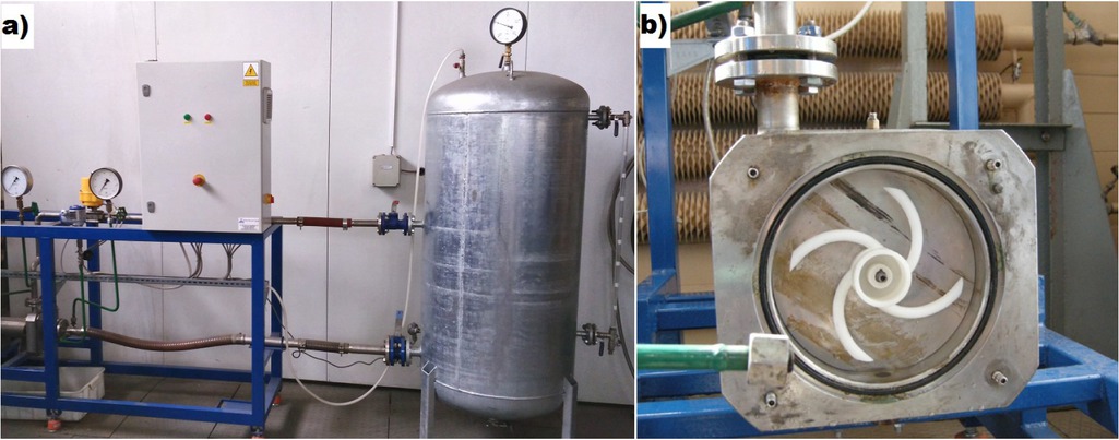
Presentation of test rig – (a) view of test rig, (b) the test rig model pump without the front panel with elliptical type of multi-piped impeller.
Measuring instruments.
| Measuring instrument | Range | Accuracy class |
|---|---|---|
| Electromagnetic | 0.18-17.67 | 0.2% |
| flowmeter | m3/h | |
| Arkon MAGS1-ST DN25 | (0.1-10 m/s) | |
| PN40 | ||
| Pressure gauge (suction) | −0.7 to 0.5 | 0.1% |
| FUJI FPK 01 | bar | |
| Pressure gauge | 0–30 bar | 0.1% |
| (discharge) FUJI FPK 03 | ||
| Active power transducer | 0–3000 W | 0.3% |
| METROL PP73 | ||
| Temperature transducer | 0–50∘C | ±0.9∘C |
| FLEXTOP |
The results of measurements of energetic characteristics of the model pump in the base configuration were shown in Figure 5.
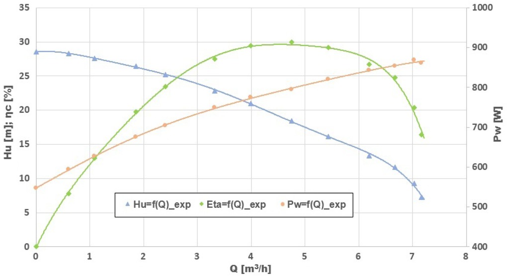
Characteristics of the model pump with an annular casing and a multi-piped impeller.
As show energetic characteristics of the model pump in Figure 5 the Best Efficiency Point (BEP) of researched pump is characterized by the following operating parameters: pump capacity Q = 4.8 m3/h (va = 6 m/s, Re was about 59·103), total pump head Hu = 18.4 m, total efficiency ηc = 29.9%. This value will be used to build a numerical model of pump with annular casing.
3 Numerical simulations
In order to identify flow phenomena occurring during the liquid flow in the stator type and to determine the rational flow geometry (which has optimal operating parameters), numerical flow analyzes were made using CFD (Computational Fluid Dynamics). As a base liquid model of pump – geometry of an annular casing and a multi-piped impeller implemented in the test rig pump – was created as a 3D model in Catia software. Further, geometry of the impeller remained unchanged. However, the type and construction of stators cooperating with the impeller were altered. Geometry of basic annular casing was calculated and designed according to theory included in [3, 4].
In order to perform the calculations Ansys Fluent from Ansys Workbanch 18.2 package was used. The geometric model of the pump consisted of the following volumes: inlet, impeller, annular-type casing (and volute casing in late calculations), outlet. The simplified geometric model of the pump used for discretization was presented in Figure 6.
Simplified model of flow geometry of a multi-piped pump with an annular casing.
To determine an optimal size of a grid from accuracy and speed of calculation point of view the GIT (Grid Independence Test) was performed. The calculations were performed for six variants of grids, which differed in size of the element (about 30% each). In each case the grid was built from the tetrahedral elements and concentrated in the areas of walls of the impeller and stator (used function Inflation in Ansys Fluent). For further calculations, the smallest size of the calculation grid was assumed, for which the discrepancies in the results of the comparison parameters (in this case total head pump Hu and total moment on the impeller rotating surfaces Mt) with the next gradation of mesh were in the range: 2.8% for Hu and 0.9% for Mt. In chosen grid the minimum size of element was 0.2 mm and total quantity of tetrahedral elements was 29 million. The y + parameter on rotating surfaces does not exceed 1.
The all numerical calculations were performed as transient flow (PISO algorithm, second-order upwind for all equations, double precision Solver, convergence criterion for each equation was ϵ = 10−6) in Ansys Fluent software. Rotational speed of the multi-piped impeller was constant and was n = 2870 rpm. For one rotation of an impeller 120 time steps were assumed, the value of one time step determined in accordance with [8] was ts = 5.2·10−4 s. The calculations were performed by means of a turbulence model k-ω SST, which one was choose as optimal turbulence model by procedure described accordance with [5, 8]. Other – necessary for calculations – boundary conditions were defined compliant with Figure 5, as:
Inlet model – velocity of the liquid at the inlet corresponding the assumed efficiency and intensity of turbulence Ti = 4%.
Walls – velocity of the liquid in a perpendicular direction to the wall ux = 0, zero pressure gradient dp/dn = 0.
Outlet model (diffuser) – the assumed pressure at the outlet p = 400 kPa, intensity of reverse flow turbulence Tibf = 2%, constant liquid viscosity, constant mass flow.
To evaluate correctness of the assumptions for the numerical model the validation of numerical results was performed by comparing them with the experimental test results in the whole range of a pump characteristic. In the whole area of a pump with a multi-piped impeller and annular casing the difference between the experimental results and numerical ones does not exceed 3%. Numerical characteristics coincided with the experimental characteristics of model pump (Figure 5). The verified numerical model was applied in the tests on the influence of the type and construction of the stator cooperating with a multipiped impeller on the pump’s energetic parameters.
Main operating parameters of the tested centrifugal pump were determined in compliance with the following equations:
The total efficiency of the pump (4) was determined assuming values of mechanical efficiency ηm = 0.90 and volumetric efficiency ηv = 0.92. Mechanical efficiency can be treated as a constant value, because it depends on the losses in bearings and sealing. Volumetric efficiency mainly depends on the pressure difference in an impeller gap sealing what it is unchangeable in our tests. Due to this fact the volumetric efficiency can be treated as constant as well. The hydraulics efficiency is the key factor especially for pumps working in ultra-low kinematic specific speed – it mainly affects the total pump efficiency.
The cooperation of the multi-piped impeller with two types of stators was analyzed in this paper: an annular casing and volute casing – with different configurations of
their geometric features. Outlet elements were designed in accordance with commonly used theoretical models based on one-dimensional flow theory of centrifugal pump (according to the constant and averaged velocity of liquid in the stator after impeller outlet).
The algorithm of numerical simulation of flow geometry rationalization was prepared to analyze the cooperation of a multi-piped impeller with an annular casing at various configurations of construction features. The following geometrical parameters of stator were the researched (Figure 7a)
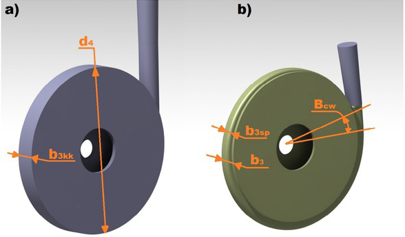
Analysed features of flow geometry for both types of stator: a) annular casing, b) volute casing.
In first step – impact of the width b3kk of the cross-section – basic value of width of model pump was 22.5 mm.
After finding a rational value of width, the next step was to research the outer diameter d4 of the channel – basic value of outer diameter of model pump was 180 mm.
After finding a rational value of outer diameter, the last step was to research the cross-section shape – basic was rectangular profile.
Then the algorithm of numerical simulation of flow geometry rationalization was prepared to analyze the cooperation of a multi-piped impeller with a volute casing at various configurations of its geometric features. The following parameters were tested (Figure 7b)
In first step – impact of the angle Bcw of the beginning of the volute tongue – basic value angle of theoretical spiral casing was 0∘.
After finding a rational value of angle, the next step was to research the width b3sp of spiral part of stator – basic value of width was 18.5 mm.
After finding a rational value of width, the last step was to research the cross-section shape – basic was rectangular profile.
The important information – the width of non-spiral part of stator b3 was constant in all numerical calculation and was equaled rational value of width b3kk of annular casing (orange dimension b3 = 18.5 mm in Figure 7b)
The Table 2 shown research changes of geometrical parameters of stators. Range of changes of value, base value of parameters (initial parameters of simulations) and rational value of them was contained. Base value of geometrical parameters of annular casing was taken from model pump (from test rig). Initial value of geometrical parameters of volute casing was calculated.
Research changes of geometrical parameters of stator type.
| Type of stator | Parameter | Range | Base value | Rational value |
|---|---|---|---|---|
| Annular casing | b3kk | 14 mm ÷ 27 mm | 22.5 mm | 18.5 mm |
| d4 | 160 mm ÷186 mm | 180 mm | 164 mm | |
| cross-section | rectangular profile | rectangular | rectangular | |
| shape | semi-circular profile | profile | profile | |
| trapezoidal profile | ||||
| Volute casing | Bcw | 0 – 30∘ | 0∘ | 15∘ |
| b3 | constant value | 18.5 mm | 18.5 mm | |
| b3sp | 10 mm ÷19 mm | 18.5 mm | 14 mm | |
| cross-section | rectangular profile | rectangular | rectangular | |
| shape | semi-circular profile trapezoidal profile | profile | profile |
4 Results of numerical research
The results of the numerical calculations of change geometrical parameters show Figure 8 for annular casing and Figure 9 for volute casing. Rationalization of flow geometry of stator has improved the parameters of the pump in both construction. Table 3, on the other hand, shows the results obtained after an alteration of the shape of a channel’s profile.
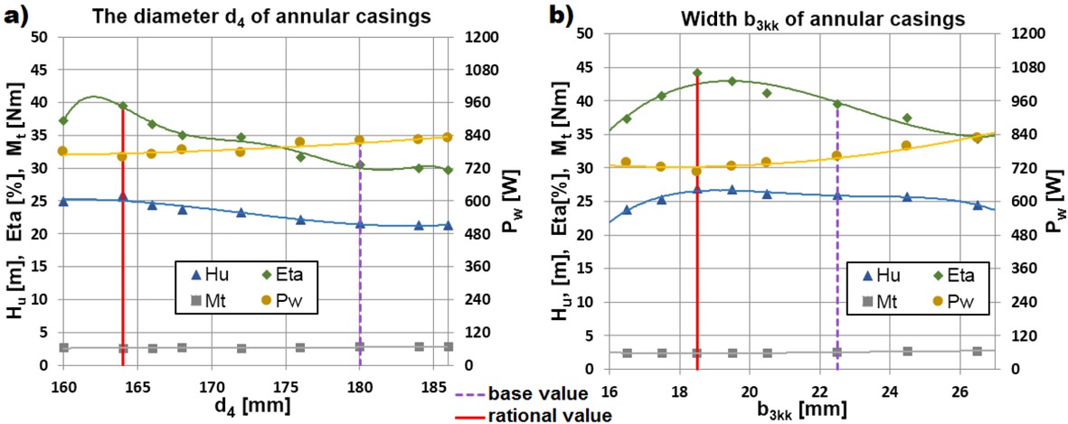
Influence of changes of the diameter d4 (a) and width b3kk (b) of the annular casing.
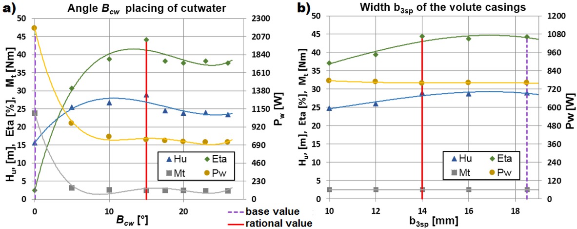
Influence of changes of the angle Bcw location of a volute tongue (a) and the width b3sp (b) of the volute casing.
Influence of changes in the shape of the cross-sectional profile in both types of stators.
| Annular casing | ||||||||
|---|---|---|---|---|---|---|---|---|
| Lp | Profile | Q | Mt | H | Ph | Pw | ηh | ηc |
| - | m3/h | Nm | m | W | W | % | % | |
| 1 | rectangular profile | 4.8 | 2.631 | 25.57 | 387.5 | 790.5 | 49.02 | 40.57 |
| 2 | semi-circular profile | 4.8 | 3.023 | 25.22 | 355.4 | 908.5 | 41.32 | 34.21 |
| 3 | trapezoidal profile | 4.8 | 2.765 | 25.81 | 386.8 | 831.1 | 47.75 | 39.54 |
| Volute casing | ||||||||
|---|---|---|---|---|---|---|---|---|
| Lp | Profile | Q | Mt | H | Ph | Pw | ηh | ηc |
| - | m3/h | Nm | m | W | W | % | % | |
| 1 | rectangular profile | 4.8 | 2.687 | 25.17 | 389.3 | 807.4 | 48.23 | 39.93 |
| 2 | semi-circular profile | 4.8 | 2.935 | 26.77 | 375.7 | 882.1 | 43.73 | 36.21 |
| 3 | trapezoidal profile | 4.8 | 2.811 | 26.71 | 374.9 | 844.8 | 45.56 | 37.72 |
While analyzing the obtained numerical results of pump with both types of stators and multi-piped impeller it can be noticed that:
As show Figure 8, reduction of annular casing geometry (represented by outer diameter d4 and width b3kk of channel) by about 26% caused a relative increase in total efficiency by 12 percent point, total head pump of 34% and decrease in power consumption of almost 9%.
Reduction of volute casing geometry (represented by width b3kk of spiral part of channel) by about 20% caused a relative increase in total efficiency by 13 pp., total head pump of 30% and decrease in power consumption by the pump of almost 7% (show in Figure 9).
The angle Bcw of the volute tongue – as show Figure 9a – in its low values is strongly affecting the pump operating parameters. It determines the width of the gap between the impeller and the tongue. Reducing the gap caused an increase in local resistances of flow.
The shape of the cross-section of the both stator type does not have a positive effect on the energy parameters tested pump. As show table 3, the base rectangular shape of the channel is characterized by the highest efficiency and total head pump.
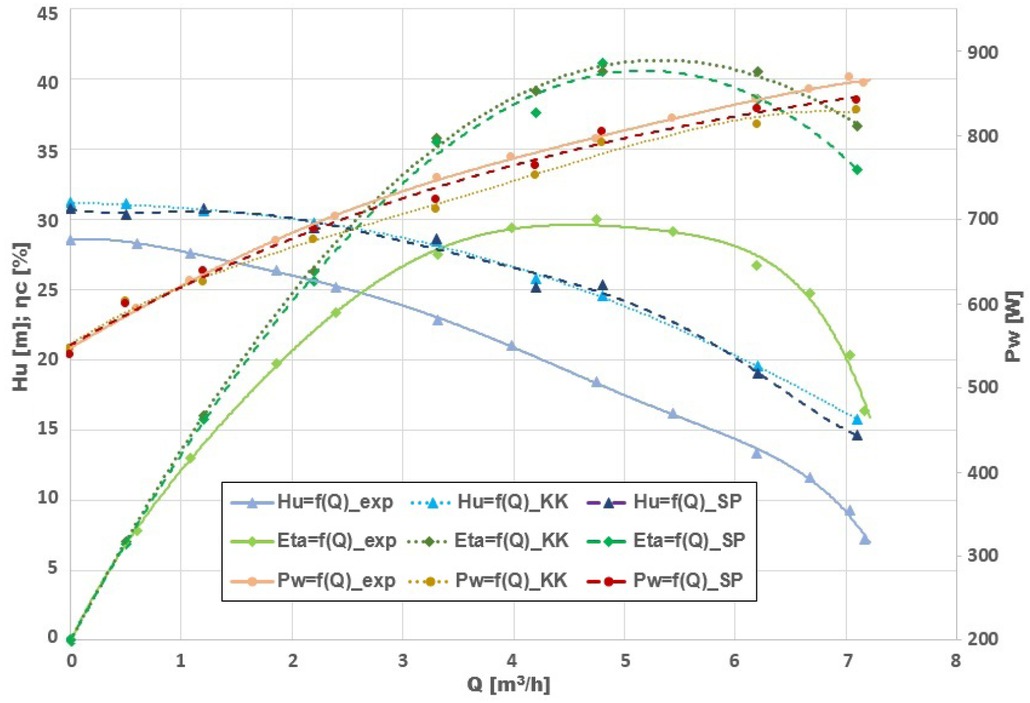
Characteristics of the base model pump (exp) and pump with rational geometry of both types of stator: annular casing (KK) and volute casing (SP).
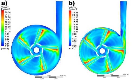
Distribution of liquid velocity on central plane (SPAN50) for: a) base model pump, b) pump with rational flow geometry of annular casing.
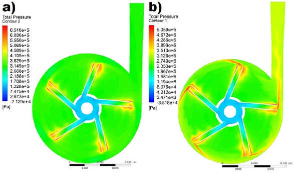
Distribution of total pressure on central plane (SPAN50) for: a) base model pump, b) pump with rational flow geometry of annular casing.
The characteristics of the centrifugal pump with a multi-piped impeller cooperating with the basic construction of annular casing used in model pump of test rig (index EXP), rational geometry of the annular casing (KK) and with the optimal volute casing (SP) obtained in numerical calculations was presented in Figure 10.
In the pictures the distribution of velocity vectors (Figure 11) and the distribution of total pressure (Figure 12) were presented. The results of numerical calculations for the model pump and pump with rational geometry of the stator – annular casing – were compared with each other on the central plane of the pump (SPAN50), across impeller, annular casing and diffuser. Reducing the stator geometry (outer diameter d4 and width b3kk for annular casing, width b3sp for volute casing, cross-section shape for both stators) caused the slight decrease of the liquid velocity after impeller outlet while uniforming its distribution along the whole perimeter. Consequently hydraulic losses are lower – lack of recirculation and turbulence areas. Furthermore, decreasing the stator geometry (both for annular casing and volute casing) resulted in a considerate enhancement of the uniformity of static and total pressure distribution. Working conditions of an outlet diffuser at rational geometry of annular casing were improved, it is used in a much higher degree, however, still liquid does not flow into it with the whole width of the cross-section.
5 Conclusion
As shown in paper, the annular casing of model pump (from test rig shows in Figure 3 and Figure 4; represented by index EXP in Figure 10) cooperating with multi-piped impeller – designed in accordance with [3, 4] – reached far poorer operating parameters than the rational construction of stator type (in a comparison with the same multipiped impeller).
A proper choice of the construction and type of stator cooperating with a multi-piped impeller can attain a relative increase of efficiency of nearly 12 percent point, the growth of total head pump over 25% and decrease in power consumption by the pump of almost 9% comparison with the one based on literature. This surplus gives such of opportunities for further rationalization of multi-piped impeller geometry (for example reducing the outer diameter of impeller).
While analyzing the cooperation results of a multipiped impeller with the volute casing, it can be noticed that the results obtained for the cooperation with the annular type casing are virtually comparable. Annular channel is easier and cheaper to produce compared to a spiral channel. This also confirms the thesis put forward in the literature [3], the author believes that for pumps with extremely low specific speed it is better to use a stator with a constant cross-section than another stator type, because difference in efficiency are negligible. It appears that, due to the ease of construction, the annular type casing is the best choice for cooperation with a hole impeller in the range of extremely low specific speed nq<10.
Knowledge concerning construction of hydraulic elements – especially in type of stators which was researched in this article – of centrifugal pumps working in the range of parameters corresponding ultra low specific speed (nq < 10) is insufficient.
For efficiency corresponding nominal best efficiency point (BEP) calculation error [9] did not exceed 1.9% – it suggest high level of confidence of used analytics and numerical models.
Acknowledgement
Calculations have been carried out using resources provided by Wroclaw Centre for Networking and Supercomputing (http://wcsspl), grant No. 444/2017.
References
[1] Kelder J.D.H., Dijkers R.J.H., van Esch B.P.M., Kruyt N.P., Experimental and theoretical study of the flow in the volute of a low specific-speed pump Fluid Dynamics Research, 2001, p. 267-280, 28.10.1016/S0169-5983(00)00032-0Search in Google Scholar
[2] Skrzypacz J., Wirnik pompy wirowej PL212505B1, 2012.Search in Google Scholar
[3] Gulich J., Centrifugal Pumps Springer, Berlin, 2008Search in Google Scholar
[4] Jędral W., Pompy wirowe Oficyna Wydawnicza Politechniki Warszawskiej, Warszawa, 2014.Search in Google Scholar
[5] Skrzypacz J., Numerical modelling of flowphenomena in a pump with a multi-piped impeller Chemical Engineering and Processing, 2014, p.58-66, 75.10.1016/j.cep.2013.11.003Search in Google Scholar
[6] VEB Kombinat Pumpen und Verdichter Halle, Technisches Hand-buch Pumpen, VEB Verlag Technik, 1987.Search in Google Scholar
[7] The European Standard EN ISO 9906:2000, Rotodynamic pumps. Hydraulic performance, acceptance tests Grades 1 and 2, BSI, 2003.Search in Google Scholar
[8] Jasak H., Turbulence Modelling for CFD (website status available on the date: 25.06.2018) http://www.powerlab.fsb.hr/ped/kturbo/OpenFOAM/SummerSchool2009/lectures/Turbulence.pdfSearch in Google Scholar
[9] Celik I.,. Karatekin O, Numerical Experiments on Application of Richardson Extrapolation With No uniform Grids ASME Journal of Fluid Engineering, 1997, p.584-590, 119.10.1115/1.2819284Search in Google Scholar
© 2018 B. Chomiuk and J. Skrzypacz, published by De Gruyter
This work is licensed under the Creative Commons Attribution-NonCommercial-NoDerivatives 4.0 License.
Articles in the same Issue
- Regular Article
- Real-scale comparison between simple and composite raw sewage sampling
- 10.1515/eng-2018-0017
- The risks associated with falling parts of glazed facades in case of fire
- Implementation of high speed machining in thin-walled aircraft integral elements
- Evaluating structural crashworthiness and progressive failure of double hull tanker under accidental grounding: bottom raking case
- Influence of Silica (SiO2) Loading on the Thermal and Swelling Properties of Hydrogenated-Nitrile-Butadiene-Rubber/Silica (HNBR/Silica) Composites
- Statistical Variations and New Correlation Models to Predict the Mechanical Behavior and Ultimate Shear Strength of Gypsum Rock
- Analytic approximate solutions to the chemically reactive solute transfer problem with partial slip in the flow of a viscous fluid over an exponentially stretching sheet with suction/blowing
- Thermo-mechanical behavior simulation coupled with the hydrostatic-pressure-dependent grain-scale fission gas swelling calculation for a monolithic UMo fuel plate under heterogeneous neutron irradiation
- Optimal Auxiliary Functions Method for viscous flow due to a stretching surface with partial slip
- Vibrations Analysis of Rectangular Plates with Clamped Corners
- Evaluating Lean Performance of Indian Small and Medium Sized Enterprises in Automotive Sector
- FPGA–implementation of PID-controller by differential evolution optimization
- Thermal properties and morphology of polypropylene based on exfoliated graphite nanoplatelets/nanomagnesium oxide
- A computer-based renewable resource management system for a construction company
- Hygrothermal Aging of Amine Epoxy: Reversible Static and Fatigue Properties
- The selected roof covering technologies in the aspect of their life cycle costs
- Influence of insulated glass units thickness and weight reduction on their functional properties
- Structural analysis of conditions determining the selection of construction technology for structures in the centres of urban agglomerations
- Selection of the optimal solution of acoustic screens in a graphical interpretation of biplot and radar charts method
- Subsidy Risk Related to Construction Projects: Seeking Causes
- Multidimensional sensitivity study of the fuzzy risk assessment module in the life cycle of building objects
- Planning repetitive construction projects considering technological constraints
- Identification of risk investment using the risk matrix on railway facilities
- Comparison of energy parameters of a centrifugal pump with a multi-piped impeller in cooperation either with an annular channel and a spiral channel
- Influence of the contractor’s payment method on the economic effectiveness of the construction project from the contractor’s point of view
- Special Issue Automation in Finland
- Diagnostics and Identification of Injection Duration of Common Rail Diesel Injectors
- An advanced teaching scheme for integrating problem-based learning in control education
- A survey of telerobotic surface finishing
- Wireless Light-Weight IEC 61850 Based Loss of Mains Protection for Smart Grid
- Smart Adaptive Big Data Analysis with Advanced Deep Learning
- Topical Issue Desktop Grids for High Performance Computing
- A Bitslice Implementation of Anderson’s Attack on A5/1
- Efficient Redundancy Techniques in Cloud and Desktop Grid Systems using MAP/G/c-type Queues
- Templet Web: the use of volunteer computing approach in PaaS-style cloud
- Using virtualization to protect the proprietary material science applications in volunteer computing
- Parallel Processing of Images in Mobile Devices using BOINC
- “XANSONS for COD”: a new small BOINC project in crystallography
- Special Issue on Sustainable Energy, Engineering, Materials and Environment
- An experimental study on premixed CNG/H2/CO2 mixture flames
- Tidal current energy potential of Nalón river estuary assessment using a high precision flow model
- Special Spring Issue 2017
- Context Analysis of Customer Requests using a Hybrid Adaptive Neuro Fuzzy Inference System and Hidden Markov Models in the Natural Language Call Routing Problem
- Special Issue on Non-ferrous metals and minerals
- Study of strength properties of semi-finished products from economically alloyed high-strength aluminium-scandium alloys for application in automobile transport and shipbuilding
- Use of Humic Sorbent from Sapropel for Extraction of Palladium Ions from Chloride Solutions
- Topical Issue on Mathematical Modelling in Applied Sciences, II
- Numerical simulation of two-phase filtration in the near well bore zone
- Calculation of 3D Coordinates of a Point on the Basis of a Stereoscopic System
- The model of encryption algorithm based on non-positional polynomial notations and constructed on an SP-network
- A computational algorithm and the method of determining the temperature field along the length of the rod of variable cross section
- ICEUBI2017 - International Congress on Engineering-A Vision for the Future
- Use of condensed water from air conditioning systems
- Development of a 4 stroke spark ignition opposed piston engine
- Development of a Coreless Permanent Magnet Synchronous Motor for a Battery Electric Shell Eco Marathon Prototype Vehicle
- Removal of Cr, Cu and Zn from liquid effluents using the fine component of granitic residual soils
- A fuzzy reasoning approach to assess innovation risk in ecosystems
- Special Issue SEALCONF 2018
- Brush seal with thermo-regulating bimetal elements
- The CFD simulation of the flow structure in the sewage pump
- The investigation of the cavitation processes in the radial labyrinth pump
- Testing of the gaskets at liquid nitrogen and ambient temperature
- Probabilistic Approach to Determination of Dynamic Characteristics of Automatic Balancing Device
- The design method of rubber-metallic expansion joint
- The Specific Features of High-Velocity Magnetic Fluid Sealing Complexes
- Effect of contact pressure and sliding speed on the friction of polyurethane elastomer (EPUR) during sliding on steel under water wetting conditions
- Special Issue on Advance Material
- Effect of thermo-mechanical parameters on the mechanical properties of Eurofer97 steel for nuclear applications
- Failure prediction of axi-symmetric cup in deep drawing and expansion processes
- Characterization of cement composites based on recycled cellulosic waste paper fibres
- Innovative Soft Magnetic Composite Materials: Evaluation of magnetic and mechanical properties
- Statistical modelling of recrystallization and grain growth phenomena in stainless steels: effect of initial grain size distribution
- Annealing effect on microstructure and mechanical properties of Cu-Al alloy subjected to Cryo-ECAP
- Influence of heat treatment on corrosion resistance of Mg-Al-Zn alloy processed by severe plastic deformation
- The mechanical properties of OFHC copper and CuCrZr alloys after asymmetric rolling at ambient and cryogenic temperatures