Vibrations Analysis of Rectangular Plates with Clamped Corners
-
 and
and

Abstract
This paper discusses the fundamental natural frequency of a thin elastic rectangular, isotropic and orthotropic, plates with clamped corners. Rayleigh’s method was used to analytically calculate the plate lowest natural frequency. In this solution, the vibration mode shape was assumed in a form that certifies the displacement as well as the rotational boundary conditions of the current problem. Finally, this paper provides useful information for evaluating the natural frequency of a plate with fixed corners with different mass attachments configurations.
1 Introduction
Rectangular elastic plates [1, 2] are widely used in engineering applications; e.g. in printed circuit boards and solar collecting panels. The exact solutions of free vibration of elastic plates are possible only for a few cases, particularly for plate structures with well-defined boundary conditions. However, real-life vibration problems may pose some difficulties in satisfying boundary conditions, such as plates having fixed (or clamped) corners. In these cases, only approximate solutions, using Rayleigh methods, are available [3].
In engineering applications, plates with clamped corners frequently appear in the fatigue life analysis of electronic printed circuit boards (PCBs). For the PCBs, the clamped constraint can arise from the fact that the elastic plate is clamped at each corner using threaded screws, washers and nuts to attach the plate structure to a base support. This type of attachment prevents both displacement and rotation of the structure at the support locations. This kind of problem has been thoroughly investigated using the analytical solution of the superposition method invented by Gorman [5, 6, 7, 8, 9, 10]. However, this analytical-type solution is very complicated and considered to be impractical.
A similar problem that has been investigated in literature is the vibration of elastic plate with pinned corners. The pinned-corner support boundary condition scheme, unlike the clamped corner scheme, only prevents displacements at the support locations, having no restriction on the rotation. Xiang-sheng [11] used Rayleigh method to analytically approximate the first resonant frequency of a plate having point-pinned supports at plate corners. Kim et al. [12, 13] used beam shape functions to solve for the deflections of plates with point supported at corners. Kerstens [14, 15] used a combination of Rayleigh-Ritz method and modal constraint method to obtain the free vibration problem of plates with such supports. As a powerful tool, the finite element analysis (FEA) has also been extensively used in the vibration analysis of plates with corner supports. Raju et al. [16] and Rao et al. [17] studied the natural frequencies of point-supported elastic plates using finite element method. Pitarresi and Kunz [18, 19] developed a simple technique using two-dimensional non-linear least-squares fit, and finite element simulations, to study the natural frequency of plates having point supports. Recently, Gharaibeh et al. [20, 21] employed the assumed mode method to evaluate the fundamental natural frequency of corner-supported plates using an electronic package.
In addition, elastic rectangular plates having corner supports may exist in many renewable energy and power generation systems such as concentrating solar power (CSP) systems, including solar dishes, parabolic trough solar collectors, and solar central receiver systems. The analysis and characteristics of vibrations of rectangular plates has been widely and extensively investigated based on various techniques. For example, Torabi et al. [22] studied the vibration characteristics of a rectangular plate having a circular central hole with point support, based on the Rayleigh-Ritz method, which is widely used, based on orthogonal polynomials and beam functions. Similarly, Li [23] employed the same approach to characterize vibrations of rectangular plates with general elastic boundary supports. Watkins et al. [24] computed normalized frequencies of elastically point-supported rectangular plates using Eigensensitivity analysis. Shahrjerdi et al. [25] used second-order shear deformation theory (SSDT) to study the vibration of solar-graded plates. Du et al. [26] employed Fourier series method for the in-plane vibration analysis of rectangular plates with elastically restrained edges.
The current work discusses the fundamental natural frequency of an elastic rectangular plate having fixed (or clamped) corners using the Rayleigh method. Both isotropic and orthotropic material systems were considered. In this paper, we first start by introducing the problem of the plate with clamped corners and resulting boundary conditions. This is followed by the use of the Rayleigh method in the system’s first natural frequency analysis. Subsequently, the careful selection of the mode shape function that satisfies the displacement and rotational boundary conditions of the problem is also presented. Finally, the natural frequency results for several geometric and mass attachment configurations are discussed in detail.
2 Description of the Problem
The plate under consideration in the present work is shown in Figure 1. The supports on the plate corners prevent both displacements and rotations at the support locations, and the edges are completely free elsewhere. The plate width is (a) and length is (b) with thickness (h). The complete set of boundary conditions can be described as:
Displacement

Plate with clamped corners schematic.
Rotations
Moments
Effective shear forces
3 Natural Frequency Analysis by Rayleigh’s Method
As previously mentioned, the present work aims to produce an approximate analytical solution for calculating the first natural frequency of a plate with clamped corners using Rayleigh’s method. Therefore, it is essential to express the general energy of the system, which is composed of the potential and kinetic energies of the plate structure. Considering an isotropic plate having a constant thickness, the plate potential energy (V) can expressed as [27]:
where D =
The plate kinetic energy (T) is [27]:
where ρ is the mass per unit volume of the plate material; ẇ is the plate velocity in the lateral direction. The double integrals shown in Eq. (5) and Eq. (6) are evaluated over the plate surface area A.
The deflection of the plate, whose motion is harmonic, is:
where î is the complex number î =
To use Rayleigh’s method, which is based on the energy conservation theorem, the maximum potential energy (Vmax) of the system must be equal to the kinetic energy (Tmax) of the system [8]:
where,
Therefore, the first natural frequency of the plate is written as:
Considering orthotropic plate material system, the kinetic energy of the plate is still expressed as in Eq. (6) and Eq. (10) above. However, the potential energy is written as [28]:
where:
By applying Rayleigh’s method as shown previously, the natural frequency of the orthotropic plate can be expressed as:
The accuracy of the calculated natural frequency of Eq. (11) and Eq. (13) greatly depends on the engineered selection of the mode shape function, W(x,y), to be discussed next.
4 Mode Shape Selection
As explained earlier, the proper selection of the mode shape in the Eq. (11) and Eq. (13) is very important. This mode function should be carefully selected in a mathematical form that satisfies the problem displacement as well as rotational boundary conditions. For the current analysis, the plate is fixed in all directions on the corners and free elsewhere. As formulated in Eq. (1) to Eq. (4), this type of constraint will result in zero displacements and rotations at the corners. Whereas the plate deflections and rotations on the edges are different from zero. Therefore, the mode shape of this problem can be formulated as:
where a and b are the plate dimensions in x and y directions, respectively. Also, constants C1 and C2 are the deflections of the midpoints of the plate sides in x and y directions, respectively. The constant C3 represents the displacement of the plate center
Obviously, the mode shape formulated in Eq. (14) completely satisfies the displacement as well as the rotation boundary conditions of Eq. (1) and Eq. (2). However, the satisfaction of the bending moment and shear forces of Eq. (3) and Eq. (4), respectively, are not adequately achieved. Here, if we can satisfy the bending moment and/or effective shear forces boundary conditions, we might be able to greatly increase the calculated natural frequency of Eq. (11) and (13). Furthermore, this can decrease the number of the independent constants of the mode shape function, Eq. (14), therefore achieving much simpler solution. Consequently, we aim to satisfy the shear forces conditions of Eq. (4), having y = 0 and x = 0, thus obtaining:
where β1 and β2 are constants depends on the plate aspect ratio
By applying Eq. (15) to Eq. (18), and into Eq. (14), the mode shape function can be modified to:
As can be clearly seen in Eq. (19), the number of independent constants in the mode shape are reduced from three to one (C3). This will result, as expected, in much simpler and accurate solution for the plate with clamped corners problem.
For the orthotropic plate analysis, the shear boundary conditions of the current plate problem become [28]:
where Dxy = 2Dxνy + 2Dk.
Following the same procedure above, the mode shape constants of Eq. (19) are obtained as:
5 Results and Discussions
Plate with fixed corners with no mass attachments
To find an equation of the fixed-corners plate’s first natural frequency, and considering an isotropic plate system, we substitute Eq. (19), combined with Eq. (17) and Eq. (18), into Eq. (11) to obtain:
where a is the plate shortest length, and λ2 is the plate eigenvalue written as:
where,
It important to mention that β1 and β2 of Eq. (25) are to be obtained from Eq. (17) and Eq. (18), respectively. As this eigenvalue is a function of β1 and β2, then it is a function of plate aspect ratio b/a and Poisson’s ratio ν only. Assuming that ν = 0.3, then the values of β1, β2 and λ2 for several plate aspect ratios are summarized in Table 1.
Mode shape constants and isotropic plate eigenvalues for different plate aspect ratios (ν=0.3).
| b/a | β1 | β2 | λ2 |
|---|---|---|---|
| 1.0 | 1.700 | 1.700 | 21.916 |
| 1.5 | 0.756 | 3.825 | 12.350 |
| 2.0 | 0.425 | 6.800 | 7.2033 |
| 2.5 | 0.272 | 10.63 | 4.6175 |
| 3.0 | 0.189 | 15.30 | 3.1940 |
| 3.5 | 0.139 | 20.80 | 2.3370 |
| 4.0 | 0.106 | 27.20 | 1.7831 |
To simplify the analysis, an empirical formula for calculating the plate eigenvalue as a function of the aspect ratio of the plate has been established. For this formula, the suggested general form is:
where a1 and a2 are unknown constants that need to be determined. To determine such constants, a non-linear regression analysis using MINITAB is performed. Thus:
Eq. (27) was compared to the analytical solution data, as shown in Figure 2. From this comparison, it is found that the results of the curve-fitted equation are in agreement with the values of Table 1.

Plate eigenvalues for different plate geometries.
For an orthotropic plate, we substitute Eq. (19), combined with Eq. (21) and Eq. (22), into Eq. (13) to get:
where:
It important to mention that β1 and β2 of Eq. (29) are to be obtained from Eq. (21) and Eq. (22), respectively. This eigenvalue is a function of a/b, Ex, Ey, νx and νy.
Plate with fixed corners having mass attachments
After discussing the problem of a plate with fixed corners, we have a look at the problem of a plate with two mass attachment types:
Case 1: Plate with fixed corners with a centrally placed mass.
Case 2: Plate with fixed corners with edge-center-placed masses.
In the present analysis, only the isotropic plate material system was studied. The same procedure could be followed for orthotropic plate system.
For case 1, the concentrated mass (M) is mounted at the plate center point

Corner-clamped plate with mass attachments; (a) case 1, (b) case 2.
This mass addition will have no effect on the structure’s potential energy. Generally, however, for a plate with attached mass (either for case 1 or case 2), the kinetic energy of the system could be expressed as:
where ẇ(ζi,ηi) are the velocities of the plate at the mass fix-up locations, and N is the total number of attached masses.
Following the previously described natural frequency analysis procedure, the system’s fundamental natural frequency is:
where α is the reduced coefficient of the mass, and it is function of plate aspect ratio b/a, and Poisson’s ratio ν. Again, assuming that ν = 0.3, then the values of α for several plate aspect ratios, for both cases, are summarized in Table 2.
Reduced coeficient of the mass for several plate aspect ratios for plate with center mass ν=0.3).
| b/a | 1.0 | 1.5 | 2.0 | 2.5 | 3.0 | 3.5 | 4.0 |
|---|---|---|---|---|---|---|---|
| αCase 1 | 4.336 | 2.591 | 1.713 | 1.267 | 1.005 | 0.835 | 0.716 |
| αCase 2 | 6.876 | 5.021 | 4.204 | 3.616 | 3.154 | 2.785 | 2.486 |
It is important to mention at this point that this mass addition has no effect on the mode shape constants and plate eigenvalues, and their values are still equal to those listed in Table 1.
As done previously, a general equation to calculate the reduced coefficient of the mass, for both cases, was formulated. The suggested general form for this equation is:
where c1 and c2 are coefficients determined using a nonlinear regression analysis as c1 = 4.35, c2 = 1.32 for case 1, and c1 = 6.85, c2 = 0.72 for case 2. A comparison between the fitted formula and the actual (analytical) data of α is shown in Figure 4. For both cases, the fitted formulas are in excellent match with the analytically derived data.

The reduced coefficient of the mass vs plate aspect ratio for (a) case 1 and (b) case 2.
As a special configuration, we shall consider the mass (M) of the added mass (or masses) to be a function of the plate mass. Thus:
where n is the plate mass fraction, and it can be any positive number: i.e., if n = 0.5 or n = 2, then the total added mass is half of the plate mass or double of it, respectively. Now, substitute Eq. (33) into Eq. (31), and after some simple mathematical manipulation we achieve:
or:
where Λ2 = λ2
From Eq. (35) above, Λ2 is now function of b/a, ν and α, as well as n. Luckily, α is function of b/a (besides to ν), for both cases. Therefore, we can implicitly say that Λ2 is a function of b/a, ν and n only. As before, assuming ν = 0.3, Table 3 and Table 4 summarize the values of Λ2 for different b/a and n combinations for case 1 and case 2, respectively.
Values of Λ2 at different b/a and n for case 1 (ν=0.3).
| b/a | n | |||||||
|---|---|---|---|---|---|---|---|---|
| 0.25 | 0.50 | 0.75 | 1.0 | 1.25 | 1.50 | 1.75 | 2.0 | |
| 1.0 | 15.1814 | 12.3131 | 10.6283 | 9.4875 | 8.6496 | 8.0005 | 7.4785 | 7.047 |
| 1.5 | 8.7954 | 7.1987 | 6.2418 | 5.5869 | 5.1026 | 4.7257 | 4.4216 | 4.1696 |
| 2.0 | 5.2867 | 4.3733 | 3.8127 | 3.4239 | 3.1341 | 2.9073 | 2.7235 | 2.5706 |
| 2.5 | 3.4495 | 2.8726 | 2.5132 | 2.2619 | 2.0734 | 1.9254 | 1.8052 | 1.7049 |
| 3.0 | 2.4119 | 2.017 | 1.7687 | 1.594 | 1.4626 | 1.3591 | 1.2749 | 1.2046 |
| 3.5 | 1.7765 | 1.4896 | 1.3081 | 1.18 | 1.0834 | 1.0072 | 0.9451 | 0.8932 |
| 4.0 | 1.3612 | 1.1434 | 1.005 | 0.9071 | 0.8332 | 0.7748 | 0.7272 | 0.6874 |
Values of Λ2 at different b/a and n for case 2 (ν=0.3).
| b/a | n | |||||||
|---|---|---|---|---|---|---|---|---|
| 0.25 | 0.50 | 0.75 | 1.0 | 1.25 | 1.50 | 1.75 | 2.0 | |
| 1.0 | 13.291 | 10.4032 | 8.8324 | 7.8092 | 7.0752 | 6.5156 | 6.0707 | 5.7061 |
| 1.5 | 7.2737 | 5.6572 | 4.7896 | 4.2282 | 3.8269 | 3.5218 | 3.2796 | 3.0814 |
| 2.0 | 4.0899 | 3.1576 | 2.665 | 2.3485 | 2.1232 | 1.9524 | 1.8171 | 1.7066 |
| 2.5 | 2.5574 | 1.9653 | 1.6555 | 1.4573 | 1.3166 | 1.2101 | 1.1259 | 1.0571 |
| 3.0 | 1.741 | 1.3342 | 1.1225 | 0.9875 | 0.8918 | 0.8194 | 0.7622 | 0.7156 |
| 3.5 | 1.2606 | 0.9643 | 0.8107 | 0.7129 | 0.6436 | 0.5913 | 0.5499 | 0.5162 |
| 4.0 | 0.955 | 0.7297 | 0.6131 | 0.5390 | 0.4866 | 0.4469 | 0.4157 | 0.3901 |
To establish a formula to calculate Λ2 as a function of the plate aspect ratio and of mass fraction factor, for both cases, a general non-linear form, which is a combination of Eq. (27) and Eq. (35), was selected as follows:
Here, a1 and a2, for case 1 and case 2, are similar to those of Eq. (27). Also, d1 and d2 are two unknown coefficients. To obtain them, a multi-parametric fit was performed considering both case 1 and case 2. The resultant constant values are (d1 = 4.33, d2 = 0.29) and (d1 = 6.89, d2 = –0.26) for case 1 and case 2, respectively. Figure 5 shows a comparison between the analytically derived data and the fitted formulas for both mass attachment cases, for several plate aspect ratios. In conclusion, the Λ2 values for case 1 and case 2, from both solutions, are in a great agreement.
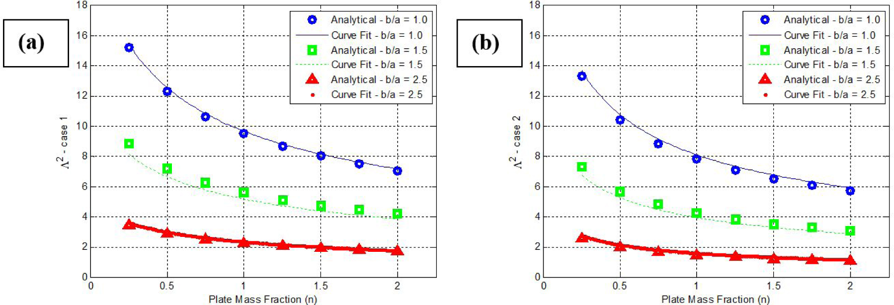
The massed plate eigenvalues (Λ2) vs. the plate mass fraction (n) at different b/a for (a) case 1 and (b) case 2.
6 Conclusions
This paper has discussed the free vibration problem of plates with clamped corners. Rayleigh’s method was used to analytically approximate the fundamental natural frequency of the plate under study. From this approximation, the plate eigenvalue was obtained for several plate dimensions. In addition, two types of mass attachments, namely plate with centrally placed mass and plate with masses on the edges centers, were discussed. A special configuration considering the mass of the added masses as a function of the plate mass was also presented. Finally, this paper developed non-linear equations for calculating the plate eigenvalues for both massed and un-massed configurations.
References
[1] Leissa, A. W., Vibration of plates, 1969, NASA SP-160.Search in Google Scholar
[2] Leissa, A. W., The free vibration of rectangular plates, Journal of Sound and Vibration, 1973, 31(3), 257-293.10.1016/S0022-460X(73)80371-2Search in Google Scholar
[3] Rayleigh, J. W. S. B., The theory of sound, 1896, (Vol. 2). Macmillan.10.1063/1.3060230Search in Google Scholar
[4] Steinberg, D. S., Vibration analysis for electronic equipment, Second edition, 2000, John Wiley & Sons.Search in Google Scholar
[5] Gorman, D. J., Free vibration of orthotropic cantilever plates with point supports, Journal of Engineering Mechanics, 1995, 121(8), 851-857.10.1061/(ASCE)0733-9399(1995)121:8(851)Search in Google Scholar
[6] Singhal, R. K., and Gorman, D. J., Free vibration of partially clamped rectangular plates with and without rigid point supports, Journal of Sound and Vibration, 1997, 203(2), 181-192.10.1006/jsvi.1996.0878Search in Google Scholar
[7] Gorman, D. J., Accurate free vibration analysis of point supported Mindlin plates by the superposition method, Journal of Sound and Vibration, 1999, 219(2), 265-277.10.1006/jsvi.1998.1874Search in Google Scholar
[8] Gorman, D. J., and Singal, R. K., Analytical and experimental study of vibrating rectangular plates on rigid point supports, AIAA Journal, 1991, 29(5), 838-844.10.2514/3.10664Search in Google Scholar
[9] Gorman, D. J., A general analytical solution for free vibration of rectangular plates resting on fixed supports and with attached masses, Journal of Electronic Packaging, 1992, 114, 239.10.1115/1.2906424Search in Google Scholar
[10] Gorman, D. J., Vibration analysis of plates by the superposition method, 1999, (Vol. 3), World Scientific.10.1142/3967Search in Google Scholar
[11] Xiang-sheng, C., Vibrations of rectangular plates supported at corner points, Applied Mathematics and Mechanics, 1989, 10(8), 751-757.10.1007/BF02019300Search in Google Scholar
[12] Kim, C. S., and Dickinson, S. M., The flexural vibration of rectangular plates with point supports, Journal of Sound and Vibration, 1987, 117(2), 249-261.10.1016/0022-460X(87)90537-2Search in Google Scholar
[13] Kim, C. S., Young, P. G., and Dickinson, S. M., On the flexural vibration of rectangular plates approached by using simple polynomials in the Rayleigh-Ritz method, Journal of Sound and Vibration, 1990, 143(3), 379-394.10.1016/0022-460X(90)90730-NSearch in Google Scholar
[14] Kerstens, J. G. M., Vibration of a rectangular plate supported at an arbitrary number of points, Journal of Sound and Vibration, 1997, 65(4), 493-504.10.1016/0022-460X(79)90899-XSearch in Google Scholar
[15] Kerstens, J. G. M., Vibration of complex structures: the modal constraint method, Journal of Sound and Vibration, 1981, 76(4), 467-480.10.1016/0022-460X(81)90264-9Search in Google Scholar
[16] Raju, I. S., and Amba-Rao, C. L., Free vibrations of a square plate symmetrically supported at four points on the diagonals, Journal of Sound and Vibration, 1983, 90(2), 291-297.10.1016/0022-460X(83)90537-0Search in Google Scholar
[17] Rao, G. V., Raju, I. S., and Amba-Rao, C. L., Vibrations of point supported plates, Journal of Sound and Vibration, 1973, 29(3), 387-391.10.1016/S0022-460X(73)80292-5Search in Google Scholar
[18] Pitarresi, J. M., and Kunz, R. J., A simple technique for the rapid estimation of the optimal support locations for a vibrating plate, Journal of Vibration and Acoustics, 1992, 114(1), 112-118.10.1115/1.2930224Search in Google Scholar
[19] Kunz, R. J., and Pitarresi, J. M., Analytical and Experimental Optimization of Support Locations for Vibrating Printed Circuit Boards,” In Ninth Annual International Electronics Packaging Conference, San Diego, California, 1989, (pp. 11-13).Search in Google Scholar
[20] Gharaibeh, M. A., Finite element modeling, characterization and design of electronic packages under vibration, 2015, PhD Dissertation, State University of New York At Binghamton.Search in Google Scholar
[21] Gharaibeh, M. A., Su, Q. T., and Pitarresi, J. M., Analytical Solution for Electronic Assemblies Under Vibration, Journal of Electronic Packaging, 2016, 138(1), 011003.10.1115/1.4032497Search in Google Scholar
[22] Torabi, K. and Azadi, A.R., Vibration analysis for rectangular plate having a circular central hole with point support by Rayleigh-Ritz method, Journal of Solid Mechanics, 2014, 6(1), 28-42.Search in Google Scholar
[23] Li W.L., Vibration analysis of rectangular plates with general elastic boundary supports, Journal of Sound and Vibrations, 2004, 273(3), 619-635.10.1016/S0022-460X(03)00562-5Search in Google Scholar
[24] Watkin, R.J. and Barton, O., Characterizing the vibration of an elastically point supported rectangular plate using eigensensitivity analysis, Thin-Walled Structures, 2009, 48, 327-333.10.1016/j.tws.2009.11.005Search in Google Scholar
[25] Shahrjerdi A., Mustafa F., Bayat M., and Majid D.L.A., Free vibration analysis of solar functionally graded plates with temperature-dependent material properties using second order shear deformation theory, Journal of Mechanical Science and Technology, 2011, 25 (9), 2195-2209.10.1007/s12206-011-0610-xSearch in Google Scholar
[26] Du J., Li W., Jin G., Yang T., and Liu, Z., An analytical method for the in-plane vibration analysis of rectangular plates with elastically restrained edges, Journal of Sound and Vibrations, 2007, 306, 908-927.10.1016/j.jsv.2007.06.011Search in Google Scholar
[27] Timoshenko, S., and Woinowsky-Krieger, S., Theory of plates and shells, 1959, Mc-Graw Hill.Search in Google Scholar
[28] Lekhnitskii, S. G., Anisotropic plates (No. FTD-HT-23-608-67), 1957, Foreign Technology Div Wright-Patterson Afb Oh.Search in Google Scholar
© 2018 Mohammad A. Gharaibeh and Amr M. Obeidat, published by De Gruyter
This work is licensed under the Creative Commons Attribution-NonCommercial-NoDerivatives 4.0 License.
Articles in the same Issue
- Regular Article
- Real-scale comparison between simple and composite raw sewage sampling
- 10.1515/eng-2018-0017
- The risks associated with falling parts of glazed facades in case of fire
- Implementation of high speed machining in thin-walled aircraft integral elements
- Evaluating structural crashworthiness and progressive failure of double hull tanker under accidental grounding: bottom raking case
- Influence of Silica (SiO2) Loading on the Thermal and Swelling Properties of Hydrogenated-Nitrile-Butadiene-Rubber/Silica (HNBR/Silica) Composites
- Statistical Variations and New Correlation Models to Predict the Mechanical Behavior and Ultimate Shear Strength of Gypsum Rock
- Analytic approximate solutions to the chemically reactive solute transfer problem with partial slip in the flow of a viscous fluid over an exponentially stretching sheet with suction/blowing
- Thermo-mechanical behavior simulation coupled with the hydrostatic-pressure-dependent grain-scale fission gas swelling calculation for a monolithic UMo fuel plate under heterogeneous neutron irradiation
- Optimal Auxiliary Functions Method for viscous flow due to a stretching surface with partial slip
- Vibrations Analysis of Rectangular Plates with Clamped Corners
- Evaluating Lean Performance of Indian Small and Medium Sized Enterprises in Automotive Sector
- FPGA–implementation of PID-controller by differential evolution optimization
- Thermal properties and morphology of polypropylene based on exfoliated graphite nanoplatelets/nanomagnesium oxide
- A computer-based renewable resource management system for a construction company
- Hygrothermal Aging of Amine Epoxy: Reversible Static and Fatigue Properties
- The selected roof covering technologies in the aspect of their life cycle costs
- Influence of insulated glass units thickness and weight reduction on their functional properties
- Structural analysis of conditions determining the selection of construction technology for structures in the centres of urban agglomerations
- Selection of the optimal solution of acoustic screens in a graphical interpretation of biplot and radar charts method
- Subsidy Risk Related to Construction Projects: Seeking Causes
- Multidimensional sensitivity study of the fuzzy risk assessment module in the life cycle of building objects
- Planning repetitive construction projects considering technological constraints
- Identification of risk investment using the risk matrix on railway facilities
- Comparison of energy parameters of a centrifugal pump with a multi-piped impeller in cooperation either with an annular channel and a spiral channel
- Influence of the contractor’s payment method on the economic effectiveness of the construction project from the contractor’s point of view
- Special Issue Automation in Finland
- Diagnostics and Identification of Injection Duration of Common Rail Diesel Injectors
- An advanced teaching scheme for integrating problem-based learning in control education
- A survey of telerobotic surface finishing
- Wireless Light-Weight IEC 61850 Based Loss of Mains Protection for Smart Grid
- Smart Adaptive Big Data Analysis with Advanced Deep Learning
- Topical Issue Desktop Grids for High Performance Computing
- A Bitslice Implementation of Anderson’s Attack on A5/1
- Efficient Redundancy Techniques in Cloud and Desktop Grid Systems using MAP/G/c-type Queues
- Templet Web: the use of volunteer computing approach in PaaS-style cloud
- Using virtualization to protect the proprietary material science applications in volunteer computing
- Parallel Processing of Images in Mobile Devices using BOINC
- “XANSONS for COD”: a new small BOINC project in crystallography
- Special Issue on Sustainable Energy, Engineering, Materials and Environment
- An experimental study on premixed CNG/H2/CO2 mixture flames
- Tidal current energy potential of Nalón river estuary assessment using a high precision flow model
- Special Spring Issue 2017
- Context Analysis of Customer Requests using a Hybrid Adaptive Neuro Fuzzy Inference System and Hidden Markov Models in the Natural Language Call Routing Problem
- Special Issue on Non-ferrous metals and minerals
- Study of strength properties of semi-finished products from economically alloyed high-strength aluminium-scandium alloys for application in automobile transport and shipbuilding
- Use of Humic Sorbent from Sapropel for Extraction of Palladium Ions from Chloride Solutions
- Topical Issue on Mathematical Modelling in Applied Sciences, II
- Numerical simulation of two-phase filtration in the near well bore zone
- Calculation of 3D Coordinates of a Point on the Basis of a Stereoscopic System
- The model of encryption algorithm based on non-positional polynomial notations and constructed on an SP-network
- A computational algorithm and the method of determining the temperature field along the length of the rod of variable cross section
- ICEUBI2017 - International Congress on Engineering-A Vision for the Future
- Use of condensed water from air conditioning systems
- Development of a 4 stroke spark ignition opposed piston engine
- Development of a Coreless Permanent Magnet Synchronous Motor for a Battery Electric Shell Eco Marathon Prototype Vehicle
- Removal of Cr, Cu and Zn from liquid effluents using the fine component of granitic residual soils
- A fuzzy reasoning approach to assess innovation risk in ecosystems
- Special Issue SEALCONF 2018
- Brush seal with thermo-regulating bimetal elements
- The CFD simulation of the flow structure in the sewage pump
- The investigation of the cavitation processes in the radial labyrinth pump
- Testing of the gaskets at liquid nitrogen and ambient temperature
- Probabilistic Approach to Determination of Dynamic Characteristics of Automatic Balancing Device
- The design method of rubber-metallic expansion joint
- The Specific Features of High-Velocity Magnetic Fluid Sealing Complexes
- Effect of contact pressure and sliding speed on the friction of polyurethane elastomer (EPUR) during sliding on steel under water wetting conditions
- Special Issue on Advance Material
- Effect of thermo-mechanical parameters on the mechanical properties of Eurofer97 steel for nuclear applications
- Failure prediction of axi-symmetric cup in deep drawing and expansion processes
- Characterization of cement composites based on recycled cellulosic waste paper fibres
- Innovative Soft Magnetic Composite Materials: Evaluation of magnetic and mechanical properties
- Statistical modelling of recrystallization and grain growth phenomena in stainless steels: effect of initial grain size distribution
- Annealing effect on microstructure and mechanical properties of Cu-Al alloy subjected to Cryo-ECAP
- Influence of heat treatment on corrosion resistance of Mg-Al-Zn alloy processed by severe plastic deformation
- The mechanical properties of OFHC copper and CuCrZr alloys after asymmetric rolling at ambient and cryogenic temperatures