The design method of rubber-metallic expansion joint
-
Przemysław Jaszak


Abstract
The paper present the method of designing a rubber expansion joints, intended for operation in the pressure class 25 bar. During the design used a numerical analysis,which based on the finite element method (FEM). The results from experimental test were used to correctly modeled the rubber or polyamide reinforcement. Basis on the obtained results, the hyperelastic model of the rubber was prepared, then the design of the rubber expansion joint was tested in different load case, i.e tensile or compressive deflection and pressurization.
1 Introduction
The rubber expansion joint is an elastic element of the pipeline system whose main task is to minimize the thermal and mechanical deflections as well as dampening of the noises and vibrations [1]. The main part of the expansion joint is elastic diaphragm made of rubber and a reinforcing layer. Usually the diaphragm is embedded in the metal flanges used for joining with the pipeline system – Fig. 1.
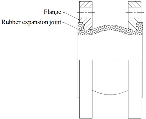
Rubber expansion joint with metallic loose flanges
The elastic diaphragm consists of several layers; internal, reinforced and external – Fig. 2. The internal layer plays the protective role for subsequent reinforcing layers. The reinforcing layer is usually made from polyamide or aramid fiber. There is an important element since its quality influences the durability and strength of the expansion joint. The last layer, that is, the external one is protection against atmospheric agents as well as it binds the all elements into one composite piece.
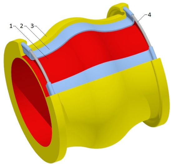
The design of elastic diaphragm: 1-internal layer; 2-reinforcing layer; 3-external layer; 4-metallic wire
The adequate selection of the rubber onto each layer of the expansion joint provides its resistance against different aggressive media. Table No 1 presents the main application of expansion joint depending on type of rubber used as the internal layer.
It is worth to mention that the rubber expansion joint is not a supporting element of the pipeline system. The proper scheme of its installation is presented in Fig. 3, where expansion joint is located between two fixed supports.
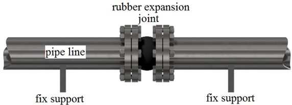
Scheme of the installation of the expansion joint in pipeline system
The displacements of the pipeline which are mitigated by means of the expansion joint could be distinguished into three basic groups:
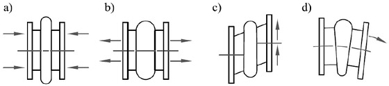
The displacement of the expansion joint: a) compressive; b) tensile; c) lateral; d) angular
Application of the expansion joint depending on the rubber.
| Internal layer | The most widely used |
|---|---|
| NR | Abrasive materials, sewages, sea water |
| CR | Cold water, sea water, cold air |
| NBR | Oil, gasoline, gas, compressed air |
| NBR/PVC | Petrol, hydraulic oil |
| EPDM | Hot water, cooling water, acids, diluted chlorine solutions |
| CSM | Acids and alkaline solutions |
| IIR | Hot compressed air, alkalines |
| HNBR | Hot oil 120 ∘C, mixtures of oil and water |
| PTFE | Extremelly agressive agents |
Guidelines for tests conditions of the rubber expansion joint are included in [1]. The main procedures are:
– Internal pressure test at room temperature (the compensator should be withstand the test pressure equals 20 bar, for 1 hour)
– Internal pressure test at 100∘ C temperature (the compensator should be withstand the test pressure equals 20 bar, for 1 hour)
– Flexibility test (at room and 100∘ C temperature with internal pressure 10 bar)
– Ageing test (at 100∘C and pressure 10 bar).
The rubber expansion joints are widely available on the market, their are mainly dedicated to the maximum pressure class PN16, i.e. the maximum working pressure is 16 bar. However, there are installations where higher pressure is required, therefore, special solutions are necessary. In this paper the design method of such an expansion joint was presented.
2 The design method of expansion joint in numerical way
To design such structures as elastic composite diaphragm is very complex since the elements made of rubber exhibit strongly non-linearity between the stress and strain relationship. In this case the best solution is to use numerical methods. One of them is a finite element method FEM. Modeling of the hyperplastic material like rubber in FEM includes adequate reflect of the real material by constitutive model.
For this reason, it is necessary to carry out experimental tests of the rubber in a multidirectional state of stress and strain. Then, based on the experimental data, the material constants of the constitutive hyperelastic model are
determined. The whole process of designing rubber expansion joint in FEM can be divided into a few basic steps:
– Testing of rubber materials,
– Adapting of the hyperelastic mathematical model,
– Preparation of the geometrical model,
– Setting the boundary conditions,
– Analyzing of the results obtained from the calculations.
2.1 Test of materials
To perform the elastic diaphragm the EPDM and NBR rubber were selected. Those materials are commonly used to the production of the elastic diaphragm of the expansion joint which are utilized in the industry. The both materials meet general requirement of the maximum operating temperature for the rubber expansion joint which equals 130∘C. The other kind of rubbers are rather dedicated in special cases, for instance in a higher operating temperatures or in applications where an aggressive media are transported. The hardness of both materials was 65 Shore. First, the tests of uniaxial tension were carried out in line with [2, 3]. The experiment was conducted by means of Instron test rig presented in Fig. 5.
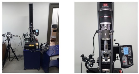
Test rig Instron model 5944
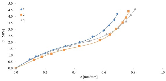
The aim of the test was to determine the stress (σ) and strain (ϵ) relationship in uniaxial state of deformation. The exemplary characteristic of uniaxial tension of the NBR rubber was shown in Fig. 6.
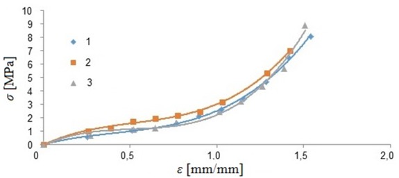
Uniaxial tension of the NBR 65∘ Sha
The second test was equibiaxial tension. Due to lack of the proper standards in this test the bubble inflation method was used in accordance with [4, 5, 6, 7, 8, 9].
This method consisted of pressurization of the rubber disc located between two metallic flanges – Fig. 7a and recording its deformation under increasing nitrogen pressure – Fig. 7b. The scheme of the test rig was presented in Figure 7c. The exemplary registered pictures of the deformed mode of the rubber sample were shown in Fig. 8.
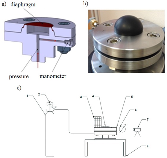
Test rig to biaxial stretch of rubber by means of bubble inflated method a) flange joint, b) view of inflated diaphragm, c) scheme of the test rig 1- reservoir, 2-regulating valve, 3-milimetric scale, 4- rubber sample, 5-flange joint, 6-manometer, 7-camera, 8-tablle
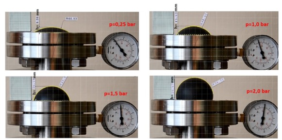
The deflection of the rubber samples under increasing pressure.
The engineering strain in the bubble pole were estimated by means of the following formula [4]:
where: ϵx, ϵy, ϵz – directional strain respectively in axis x,y,z; t0 – nominal thickness of the rubber sample; t– thickness under deflection; h –hight of the bubble ; R– radius of the flange’s hole.
The engineering stress in the bubble pole was calculated by means of the following formula [4]:
Applying the formulas (1) and (2) in the function of the pressure, the stress – strain relationship could be plotted as a biaxial characteristic presented in Fig. 9. The mechanical strength of the rubber under biaxial deflection is prominently lower than uniaxial because rupturing took place at twice lower stress and strain.
Biaxial tension of the NBR 65∘ Sha
2.2 The hyperelastic model of the rubber
To reflect the rubber behaviour the tri-parameric hiperelastic model proposed by Mooneya–Rivlina (M-R) was used [10, 11, 12, 13]. The density of the elastic strain energy is described by formula (3):
where: C10, C01, C11 – material constants, I1, I2 –Couchy-Green strain invariants.
The values of the constants C10, C01, C11 were determined based on uniaxial and biaxial tests. In Fig. 10 the fitting curves of the M-R model to the experimental data were presented.
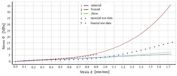
Fitting curves of the M-R model to experimental data: 1 – approximation of the uniaxial tensile ; 2 – approximation of the biaxial tensile; 3 approximation of the uniaxial shear –; 4 – experimental data set of the uniaxial tensile; 5 – experimental data set of the biaxial tensile
2.3 Geometrical model and boundary conditions
Based on geometrical model of the elastic diaphragm (Fig. 11a) the numerical model (Fig. 11b)was prepared. The discretization of the geometry was performed by hexagon elements with a higher shape function. The contact between two element (polyamide layer and rubber layer) was set as a bonded. It reflected a real behavior of this structure because during the curing process the both materials were stuck together. The steady state of structural analysis was set.
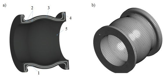
a) geometrical model: 1 – external layer, 2 – reinforcement, 3 – mid layer, 4 – wire, 5 – internal layer; b) discretized model
In the Fig. 12 the boundary condition of the numerical model was presented.
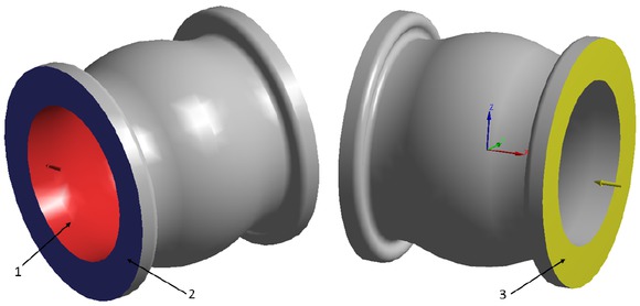
Boundary condition of the elastic diaphragm: 1 –the surface where the internal pressure was applied; 2 – the plane where fixed support was applied; 3 – the plane where displacements were applied.
The following load cases of the elastic diaphragm were analyzed.
– Internal pressure in range from 10 to 25 bar,
– compression/tension deflection up to 20 mm,
– lateral deflection up to 20 mm,
– angular deflection up to 20∘.
The M-R model (3) was prepared in two configurations for EPDM and NBR rubber for which the material constants equal C10EPDM = 0,554, C01EPDM = 0,003, C11EPDM = 0,012 and C10NBR = 0,964, C01NBR = -0,273, C11NBR = 0,066 respectively. In accordance whit the standardized construction of the elastic diaphragm its reinforcing layer (in the form of crossed braided mesh) is an circumferentially wound inside the structure. So, some fibers of the polyamide layer are parallel to the axis of the diaphragm and the other are oriented in perpendicular way. Therefore, the orthotropic model of the polyamide was used. The material properties of the polyamide model were compiled in Table 2.
Mechanical properties of the polyamide fiber of 1 mm thickness [14]
| Longitudional deformation module | Form deformation module | Poisson ratio | |||
|---|---|---|---|---|---|
| Axis direction | Value [MPa] | Plane | Value [MPa] | Plane | Value [–] |
| X | 1 200 | XY | 400 | XY | 0,43 |
| Y | 1 200 | YZ | 400 | YZ | 0,43 |
| Z | 500 | XZ | 200 | XZ | 0,35 |
3 Results
The main aim of the numerical calculation was to determine the allowable displacement of the elastic diaphragm in defined directions at constant pressure. The Figures 13 and 14 depict the exemplary maps of von Misses stress distribution of the elastic diaphragm in a selected deformation mode.
Based on these maps in the Fig. 13b and 14b it was observed that the highest stress occurs in the reinforcing layer. The exemplary chart of the stress in the reinforcing layer in the function of deformation increase was shown in Fig. 15. The allowable stress of this material is 110 MPa. Therefore, exceedance of this value determined the maximum displacement of the elastic diaphragm in particular direction. These maximum displacements for all deflecting mode were compiled in Table 3.
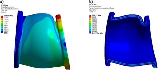
The deflection and von Misses stress distribution of the elastic diaphragm made of EPDM rubber. Load case: angular deflection at 15 deg. and internal pressure 20 bar, a) generalized deflection, b) von Mises stress distribution
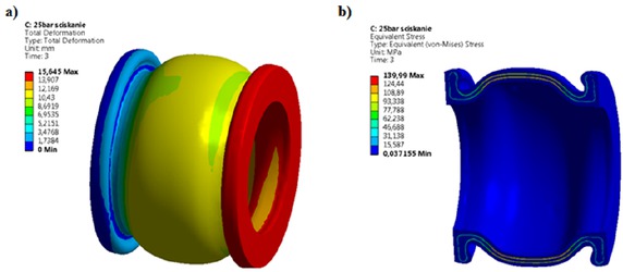
The deflection and von Misses stress distribution of the elastic diaphragm made of EPDM rubber. Load case: compressive deflection at 15 deg. and internal pressure 20 bar, a) generalized deflection, b) von Mises stress distribution
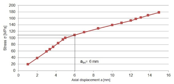
The von Misses stress in reinforcing layer depending on axial tensile displacement and internal pressure 25 bar for elastic diaphragm made of EPDM rubber.
The maximum displacement of the elastic diaphragm depending on internal pressure
| Rubber | Pressure [bar] | Displacement | |||
|---|---|---|---|---|---|
| Compression clim [mm] | Tension alim [mm] | Lateral rlim [mm] | Angular αlim [∘] | ||
| EPDM | 10 | 13 | 10 | 15 | 8 |
| 15 | 13 | 8 | 15 | 7 | |
| 20 | 12 | 7 | 15 | 7 | |
| 25 | 10 | 6 | 12 | 5 | |
| NBR | 10 | 13 | 8 | 15 | 8 |
| 15 | 12 | 6 | 15 | 8 | |
| 20 | 12 | 6 | 15 | 8 | |
| 25 | 10 | 5 | 12 | 5 | |
4 Summary
The finite element method is a helpful tool at designing and analyzing components made of rubber, especially in case a large deformation, since the rubber material exhibits a strong nonlinearity between strain and stress relationship. Using this method for designing of the rubber expansion joint enabled to checked how are the permissible deflection of the elastic diaphragm in particular directions, providing its failure-free work. It turn out that the maximum stress in the elastic diaphragm occurred in reinforcing layer regardless of kind of rubber used for internal and external layers.
References
[1] DIN 4809 Expansion joints made of elastomer compound materials (rubber expansion joints) for water heating plants, November 1986Search in Google Scholar
[2] PN ISO 37:2007, Rubber, Vulcanized Or Thermoplastic - Determination Of Tensile Stress-strain Properties,Search in Google Scholar
[3] DIN 535504 Testing of rubber-Determination of tensile strength at brake, tensile stress at yield, elongation and stress values in a tensile test, 2017Search in Google Scholar
[4] Seibert H., Scheffer T., Diebels S. “Biaxial Testing of Elastomers - Experimental Setup, Measurement and Experimental Optimisation of Specimen’s Shape”, TECHNISCHE MECHANIK 34, 2, (2014), 72 – 89: July 15, 2013,Search in Google Scholar
[5] Murphy J.S., Hanley N., The Significance of Equi-biaxial Bubble Inflation in Determining Elastomeric Fatigue Properties Elastomers, editor. A. Boczkowska, InTech 2012.Search in Google Scholar
[6] Bojtos A., ÁbrahámG., Opticalmeasuring system for equibiaxial test of hyperelastic rubber-likematerials, 9th Youth Symposium on Experimental Solid Mechanics Trieste, Italy, July 7-10, 2010, 170-173,Search in Google Scholar
[7] Brieu M., Diani J., Bhatnagar N., A New Biaxial Tension Test Fixture for Uniaxial TestingMachine—A Validation for Hyperelastic Behavior of Rubber-like Materials Journal of Testing and Evaluation Vol. 35, No. 4.Search in Google Scholar
[8] Murphy J. S., Hanley N., (2012), The Significance of Equi-biaxial Bubble Inflation in Determining Elastomeric Fatigue Properties, Published in the book Elastomers edited by Anna Boczkowska (ISBN 979-953-307-1019-5), InTech,Search in Google Scholar
[9] Palmieri G., Chiappini G., Sasso M., Papalini S., Hyperelastic Materials Characterization by Planar Tension Tests and Full-field Strain Measurement, Proceedings of the SEM Annual Conference June 1-4, 2009 Albuquerque New Mexico USA 2009 Society for Experimental Mechanics Inc,Search in Google Scholar
[10] Shahzad M., Kamran A., Zeeshan Siddiqui M., Farhan M., Mechanical Characterization and FE Modelling of a Hyperelastic Material, Material Research Vol. 18 no.5 São Carlos Sept./Oct. 2015,10.1590/1516-1439.320414Search in Google Scholar
[11] Ali A., Hosseini M., Sahari B.B., A Review of Constitutive Models for Rubber-Like Materials, American J. of Engineering and Applied Sciences 232-239, 2010,10.3844/ajeassp.2010.232.239Search in Google Scholar
[12] Jakel R., Analysis of Hyperelastic Materials with MECHANICA, Presentation for the 2nd SAXSIM | Technische Universität Chemnitz, 27. April 2010 | Rev. 1.0 – Theory and Application Examples,Search in Google Scholar
[13] Santos D., Batalha G.F., Mechanical behaviour characterizing and simulation of polyacrylate rubber, Journal of Achievements in Materials and Manufacturing Engineering Vol. 38, Issue 1, January 2010,Search in Google Scholar
[14] Engineering data sources – Ansys Workbench 15.0.Search in Google Scholar
© 2018 P. Jaszak et al., published by De Gruyter
This work is licensed under the Creative Commons Attribution-NonCommercial-NoDerivatives 4.0 License.
Articles in the same Issue
- Regular Article
- Real-scale comparison between simple and composite raw sewage sampling
- 10.1515/eng-2018-0017
- The risks associated with falling parts of glazed facades in case of fire
- Implementation of high speed machining in thin-walled aircraft integral elements
- Evaluating structural crashworthiness and progressive failure of double hull tanker under accidental grounding: bottom raking case
- Influence of Silica (SiO2) Loading on the Thermal and Swelling Properties of Hydrogenated-Nitrile-Butadiene-Rubber/Silica (HNBR/Silica) Composites
- Statistical Variations and New Correlation Models to Predict the Mechanical Behavior and Ultimate Shear Strength of Gypsum Rock
- Analytic approximate solutions to the chemically reactive solute transfer problem with partial slip in the flow of a viscous fluid over an exponentially stretching sheet with suction/blowing
- Thermo-mechanical behavior simulation coupled with the hydrostatic-pressure-dependent grain-scale fission gas swelling calculation for a monolithic UMo fuel plate under heterogeneous neutron irradiation
- Optimal Auxiliary Functions Method for viscous flow due to a stretching surface with partial slip
- Vibrations Analysis of Rectangular Plates with Clamped Corners
- Evaluating Lean Performance of Indian Small and Medium Sized Enterprises in Automotive Sector
- FPGA–implementation of PID-controller by differential evolution optimization
- Thermal properties and morphology of polypropylene based on exfoliated graphite nanoplatelets/nanomagnesium oxide
- A computer-based renewable resource management system for a construction company
- Hygrothermal Aging of Amine Epoxy: Reversible Static and Fatigue Properties
- The selected roof covering technologies in the aspect of their life cycle costs
- Influence of insulated glass units thickness and weight reduction on their functional properties
- Structural analysis of conditions determining the selection of construction technology for structures in the centres of urban agglomerations
- Selection of the optimal solution of acoustic screens in a graphical interpretation of biplot and radar charts method
- Subsidy Risk Related to Construction Projects: Seeking Causes
- Multidimensional sensitivity study of the fuzzy risk assessment module in the life cycle of building objects
- Planning repetitive construction projects considering technological constraints
- Identification of risk investment using the risk matrix on railway facilities
- Comparison of energy parameters of a centrifugal pump with a multi-piped impeller in cooperation either with an annular channel and a spiral channel
- Influence of the contractor’s payment method on the economic effectiveness of the construction project from the contractor’s point of view
- Special Issue Automation in Finland
- Diagnostics and Identification of Injection Duration of Common Rail Diesel Injectors
- An advanced teaching scheme for integrating problem-based learning in control education
- A survey of telerobotic surface finishing
- Wireless Light-Weight IEC 61850 Based Loss of Mains Protection for Smart Grid
- Smart Adaptive Big Data Analysis with Advanced Deep Learning
- Topical Issue Desktop Grids for High Performance Computing
- A Bitslice Implementation of Anderson’s Attack on A5/1
- Efficient Redundancy Techniques in Cloud and Desktop Grid Systems using MAP/G/c-type Queues
- Templet Web: the use of volunteer computing approach in PaaS-style cloud
- Using virtualization to protect the proprietary material science applications in volunteer computing
- Parallel Processing of Images in Mobile Devices using BOINC
- “XANSONS for COD”: a new small BOINC project in crystallography
- Special Issue on Sustainable Energy, Engineering, Materials and Environment
- An experimental study on premixed CNG/H2/CO2 mixture flames
- Tidal current energy potential of Nalón river estuary assessment using a high precision flow model
- Special Spring Issue 2017
- Context Analysis of Customer Requests using a Hybrid Adaptive Neuro Fuzzy Inference System and Hidden Markov Models in the Natural Language Call Routing Problem
- Special Issue on Non-ferrous metals and minerals
- Study of strength properties of semi-finished products from economically alloyed high-strength aluminium-scandium alloys for application in automobile transport and shipbuilding
- Use of Humic Sorbent from Sapropel for Extraction of Palladium Ions from Chloride Solutions
- Topical Issue on Mathematical Modelling in Applied Sciences, II
- Numerical simulation of two-phase filtration in the near well bore zone
- Calculation of 3D Coordinates of a Point on the Basis of a Stereoscopic System
- The model of encryption algorithm based on non-positional polynomial notations and constructed on an SP-network
- A computational algorithm and the method of determining the temperature field along the length of the rod of variable cross section
- ICEUBI2017 - International Congress on Engineering-A Vision for the Future
- Use of condensed water from air conditioning systems
- Development of a 4 stroke spark ignition opposed piston engine
- Development of a Coreless Permanent Magnet Synchronous Motor for a Battery Electric Shell Eco Marathon Prototype Vehicle
- Removal of Cr, Cu and Zn from liquid effluents using the fine component of granitic residual soils
- A fuzzy reasoning approach to assess innovation risk in ecosystems
- Special Issue SEALCONF 2018
- Brush seal with thermo-regulating bimetal elements
- The CFD simulation of the flow structure in the sewage pump
- The investigation of the cavitation processes in the radial labyrinth pump
- Testing of the gaskets at liquid nitrogen and ambient temperature
- Probabilistic Approach to Determination of Dynamic Characteristics of Automatic Balancing Device
- The design method of rubber-metallic expansion joint
- The Specific Features of High-Velocity Magnetic Fluid Sealing Complexes
- Effect of contact pressure and sliding speed on the friction of polyurethane elastomer (EPUR) during sliding on steel under water wetting conditions
- Special Issue on Advance Material
- Effect of thermo-mechanical parameters on the mechanical properties of Eurofer97 steel for nuclear applications
- Failure prediction of axi-symmetric cup in deep drawing and expansion processes
- Characterization of cement composites based on recycled cellulosic waste paper fibres
- Innovative Soft Magnetic Composite Materials: Evaluation of magnetic and mechanical properties
- Statistical modelling of recrystallization and grain growth phenomena in stainless steels: effect of initial grain size distribution
- Annealing effect on microstructure and mechanical properties of Cu-Al alloy subjected to Cryo-ECAP
- Influence of heat treatment on corrosion resistance of Mg-Al-Zn alloy processed by severe plastic deformation
- The mechanical properties of OFHC copper and CuCrZr alloys after asymmetric rolling at ambient and cryogenic temperatures