
Defect tolerance under environmentally assisted cracking conditions
-
Jaime Tupiassú Pinho de Castro
 ,
Rodrigo Vieira Landim
,
Rodrigo Vieira Landim

Abstract
Notch sensitivity effects under environmentally assisted cracking (EAC) conditions have been recently quantified considering the tolerance to short cracks that may start at their tips and become nonpropagating after growing for a while, a behavior that depends on the stress gradients ahead of the notch tips and on the basic material resistances to crack initiation and propagation inside an aggressive medium. This model can provide a powerful alternative design tool for the pass/nonpass criterion traditionally used to deal with such mechanical-chemical problems, since it properly considers and quantifies the stress analysis issues that affect them. The model uses the analogy between the notch sensitivity behavior under fatigue and under EAC conditions, so it quantifies how the stress gradient around the notch tips affects the tolerance to mechanically short cracks that depart from there, considering the characteristics of the loading and of the notch geometry, as well as the basic material properties inside the given environment, expressed by its EAC resistances to crack initiation from a smooth surface SEAC and to crack propagation KIEAC, without the need for any data fitting parameter. Moreover, since this model has been validated by proper tests, it can be used to propose a defect-tolerant design criterion under EAC conditions that includes the unavoidable notch effects always present in actual structural components.
1 Introduction
Various mechanisms may cause environmentally assisted cracking (EAC) problems induced by joint chemical-mechanical damage, among them stress corrosion cracking (SCC), due to stress-enhanced chemical reactions at crack tips; hydrogen embrittlement (HE), due to high hydrostatic stresses induced by the penetration of small H atoms inside the gaps of crystalline lattices and/or grain boundaries; liquid metal embrittlement (LME), due to the interaction of liquid metals like Hg, Pb, Ga, Cd, or Zn with tensioned surfaces of sensitive structural alloys; solid metal embrittlement, caused by tensioned inclusions or coatings below their melting points, as observed, e.g. in cadmium or lead-plated high-strength steels; and corrosion-fatigue, due to a synergic interaction between cyclic loads and electrochemical reactions at crack tips. No matter their differences, all such EAC mechanisms have a common feature: unlike in other corrosion problems, they depend both on the environment/material pair and on the stress state, since cracks cannot grow unless loaded by tensile stresses. Hence, they all require a sensitive material, a suitable aggressive environment, and tensile stresses at the critical point of the component (Cramer & Covino, 2003; Dietzel, 2001; Fontana, 1986; Korb & Olson, 1992; Leis & Eiber, 1997; Lisagor, 2005; Lynch, 2003; McEvily & Wei, 1972; Vasudevan & Sadananda, 2009, 2011a,b,c). As the terminology SCC enhances this mutual dependence, it probably might be profitably used to generically name all EAC mechanisms when there is no need separate them, but to avoid doubts, this practice will not be followed here.
If the tensile stresses are high enough, and if the material is sensitive to the environment it is immersed in, then EAC damage can initiate cracks in undamaged or virgin surfaces and eventually propagate them up to the fracture of the structural component. In such cases, EAC-induced damage includes a time-dependent crack nucleation period, followed by a steady crack growth phase, and eventually by the final fracture, which occurs when the stress intensity factor (SIF) of the dominant crack KI reaches the toughness of the material KC inside the aggressive medium. EAC damage can occur even under constant tensile loads, but its kinetics depend on the material-environment pair and on the stress state: it is affected by the material, including its alloy composition, its microstructural characteristics, and its thermo-mechanical history; by the chemistry of the environment; by the electrochemical state of the system relative to its surroundings; and by the stress gradients near the structural component surface. However, although the stress alone can cause failures even in inert media, it must be emphasized that EAC failures do not occur in aggressive environments without the stress contribution (Vasudevan & Sadananda, 2009).
Many aggressive environments can induce localized chemical reactions that decrease cohesive forces or surface energies in sensitive material regions, reducing the local stresses required to break their atomic bonds. EAC failures can occur even under nominally elastic stresses if the environment effect is high enough, and for some materials, they may happen in common media like water vapor or salt water. Alloy additions can significantly affect the formation of protective films and/or local electrochemical states. Microstructural features (e.g. grain size, segregation, precipitates, second phase particles, and inclusions) and/or mechanical and heat treatments (which affect the microstructure, mechanical properties, and/or the resident or residual stress state) may play an important role in EAC as well. Electrochemical factors may contribute in different ways; e.g. the applied potential has been reported to have little effect on EAC thresholds in low-alloy high-strength 4340 steels but a high effect on high-strength high-toughness maraging steels (Lisagor, 2005).
From the electrochemical point of view, EAC damage may be separated into anodic (when it involves dissolution and material at loss the crack tip) and cathodic (when the corrosive process forces embrittlement agents to penetrate inside the material microstructure without material removal from the crack tip) (Cramer & Covino, 2003). Cracks induced by EAC frequently start at small superficial defects such as corrosion pits, notches, or scratches, simply because the stresses there are increased by their stress concentration effect, or at microstructural features such as inclusions or grain boundaries, which can be more sensitive to the chemical environment. However, purely chemical models cannot describe the entire EAC process because they do not include its equally important mechanical driving force.
EAC failures can be intergranular, transgranular, or mixed, and contaminants or minor changes in the concentration level of the environment can strongly affect EAC rates as well. EAC failures are particularly dangerous because they can occur without overall corrosion evidence under low linear elastic (LE) static tensile loads, well below the material yield strength SY. Like fatigue cracks, the cracks induced by the joint effect of stress and chemical driving forces can initiate, grow, and eventually cause sudden failures without evident warning. However, unlike fatigue cracks, they can do so under constant loads. Moreover, such cracks are as difficult to detect as fatigue cracks, and they also tend to initiate at notch tips or at small surface flaws in unnotched surfaces.
In fact, if the aggressive medium is unavoidable, there are so many chemical and metallurgical details involved in practical EAC problems that they are usually solved by using a material immune to it, even if much more expensive than the original one. However, as such radical solutions ignore the stress role in EAC, they may be wasteful, to say the least. Besides, they may be useless if such problems appear only after the sensitive equipment has been operating for a while. For instance, an unexpected case of a formerly benign environment becoming propitious to sulfate-reducing bacteria proliferation and then producing unforeseen amounts of H2S occurred in the Wilmington oil field in California, USA, which originally had only trace amounts of H2S, but after a period of sea water reinjection into the well, its H2S content increased to about 1000 ppm (Bertness, Chilingarian, & Al-Bassam, 1989). The H2S gas is commonly associated with sulfide stress corrosion (SSC) and can cause serious catastrophic failures in components and equipment. Since bacteria can grow in the presence of sulfate ions and soluble organics, care to maintain the water quality must be taken by the use of bactericides or detergents and by keeping it clean enough to avoid the spread of bacteria into the well. In anaerobic conditions; e.g. inside steel pipelines, sulfate-reducing bacteria utilize the hydrogen atoms formed at cathodic sites of the metal to reduce sulfate to sulfides bring forth corroded iron and more bacteria, following reactions like
For structural integrity evaluations in such cases, and even for general structural engineering applications, it would be better to include all such complex chemical details in environmentally dependent mechanical properties, which should reflect their effects on the mechanical strength of the structural component when it is loaded inside the aggressive environment. Note, however, that the mechanical driving force for crack initiation and/or propagation under EAC conditions includes both (i) the stresses induced by externally applied loads and (ii) the internal residual stresses caused by any means. Indeed, although they may be difficult to evaluate, residual stresses can contribute to both the maximum value of the local stress σmax in uncracked components and the maximum value of the SIF, Kmax, after the crack is induced; thus, they cannot be neglected in EAC applications. If high enough for a given material-environment pair, such combined (service+residual) stresses can initiate a crack by EAC after some incubation time and then can propagate the crack under EAC rates da/dt that depend on the SIF induced by them.
Like typical fatigue crack growth (FCG) curves, such da/dt×KI curves also have three phases, as schematized in Figure 1. Phase I has a propagation threshold (true or practical) called KIEAC, below which the crack does not grow by EAC alone, and a rate very sensitive to its SIF. EAC rates in phase II, on the other hand, may present a plateau-like behavior almost independent (case A) or weakly dependent on the SIF value (case B) (Vasudevan & Sadananda, 2011a,b,c), whereas in phase III, the da/dt rates induced by EAC are again very sensitive to the SIF value, increasing quickly as it approaches the material toughness KC, which usually depends on the environment as well. Such three-phase EAC vs. SIF or da/dt×KI curves are observed in both gaseous and aqueous environments, as well as in liquid metal and in HE problems.
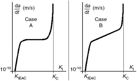
Typical da/dt×KI crack growth under EAC curves is similar to fatigue crack propagation da/dN×ΔK curves, a motivation to explore the analogy used in this work.
The similarity with the fatigue case is still more pronounced. Indeed, like in fatigue problems, it is usually accepted that there is also a strength limit SEAC below which a crack does not initiate by EAC at the surface of smooth components for a given material-environment pair. Even though the time for crack nucleation may be dependent on the load type, such SEAC limits can be measured by testing suitable smooth tensile or bending specimens immersed during sufficient time in the desired environment under various constant loads or fixed displacements, using Dixon’s (1965) staircase or up-and-down techniques, or else using very slowly increasing strain rates until a crack appears at their surfaces, following Prot’s approach (Lin, Lee, & Lu, 2011). Threshold stress intensity values, KIEAC, below which cracks do not grow under EAC conditions, can be measured as well by testing precracked standard specimens under similar procedures. Although the results of different test methods may be not identical, SEAC and KIEAC are usually accepted as mechanical properties of the material-environment pair. In fact, there are many standards that specify acceptable experimental practices to properly measure them (see, e.g. Cramer & Covino, 2003; and Korb & Olson, 1992, for a comprehensive review of such standard test methods). Figure 2 schematizes the results of an SEAC test. Note how similar this S×t curve is to traditional SN curves, which depict the material resistance to fatigue crack initiation.
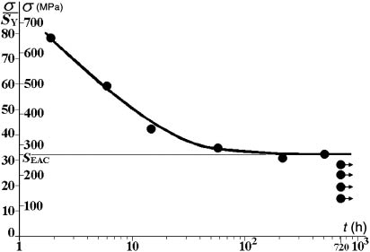
Typical S×t curve obtained by testing smooth specimen inside a given medium to identify the material resistance to crack initiation by EAC, SEAC (720 h≅1 month), which is similar to SN fatigue curves, another indication of their analogous behavior.
Due to the similitudes between the basic EAC and fatigue cracking behavior, the methodology proposed in Meggiolaro, Miranda, and Castro (2007), Wu, Imad, Nouredine, Castro, and Meggiolaro (2010), and Castro et al. (2012) to analyze tolerance to small fatigue cracks that start from notch tips has been recently extended to the EAC case (Castro & Leite, 2013; Castro, Landim, Leite, & Meggiolaro, 2015; Castro & Meggiolaro, 2013, 2014). Such an attempt is a small step toward the desired development of stress analysis procedures for dealing with EAC problems, and it is pursued in this work by investigating its applicability to other EAC mechanisms.
Fatigue damage is associated to two driving forces, one that activates cyclic and the other that activates static damage mechanisms. In this way, FCG rates on any given environment depend on ΔK and Kmax, the SIF range and maximum, or on any other equivalent pair of parameters related to them, like ΔK and R=Kmin/Kmax, the most used pair to present fatigue data (even though R is not a crack driving force). Recall that the loading includes externally applied efforts and also internal self-equilibrating residual stresses. However, as residual stresses are static load components (if not altered in service by elastoplastic loads or thermally activated mechanisms), they affect Kmax and R, but not ΔK, so they may play a relatively smaller role in fatigue than in EAC.
To propagate long cracks by fatigue under fixed {ΔK, Kmax} or {ΔK, R} loading conditions, the applied SIF range ΔK must be higher than the FCG threshold at the given R ratio, ΔKth(R)=ΔKthR. Cracks may be considered short while their FCG thresholds are smaller than the long crack FCG threshold; thus, such cracks can grow under ΔK<ΔKthR. This apparently odd behavior is, on the contrary, natural, since otherwise the stress ranges, Δσ, required to propagate short cracks at a given R would be higher than their fatigue limits, ΔSL(R)=ΔSLR, the stress range needed to initiate and propagate cracks in smooth specimens at that R ratio, a nonsense. Indeed, assuming as usual that at any given fixed R ratio the FCG process is driven by the SIF range ΔK∝Δσ√(πa), if very short cracks with size a→0 had the same ΔKthR threshold the long cracks have, they would need Δσ→∞ to grow by fatigue, a meaningless requirement (El Haddad, Smith, & Topper, 1979; El Haddad, Topper & Smith, 1979; Kitagawa & Takahashi, 1976; Lawson, Chen, & Meshii, 1999; McEvily, 1988; Sadananda & Vasudevan, 1997; Yu, DuQuesnay & Topper, 1988). Such statements assume that the stresses are induced by external loads only, but if the cracks start from notch tips or from smooth surfaces also loaded by residual stress fields caused by plastic strain gradients or by any other mechanism, such resident stresses must be added to the externally applied stresses as static loading components (which affect R but not ΔK, as mentioned above).
Microstructurally, short cracks, those small compared to the grain size gr, are much affected by microstructural barriers like grain boundaries (see, e.g. Chapetti, 2003, 2008; Krupp et al., 2004; Lorenzino & Navarro, 2013; Navarro & de los Rios, 1988; Verreman, 2008). Their study may be academically important, but as they cannot be well modeled for structural design purposes using macroscopic stress analysis techniques and isotropic properties, they are considered beyond the scope of this paper. Mechanically short cracks, on the other hand, say with sizes a>gr, may be modeled by LE fracture mechanics (LEFM) concepts if the stress field that surrounds them is predominantly LE and if the material can be treated as isotropic and homogeneous in such a scale. Since near-threshold FCG is always associated with small-scale yielding conditions, it is reasonable to expect that the classical LEFM concepts can be useful to model short cracks as well (Atzori, Lazzarin, & Filippi, 2001; Atzori, Lazzarin, & Meneghetti, 2003, 2005; Atzori, Meneghetti, & Susmel, 2005; Castro & Meggiolaro, 2015; Ciavarella & Meneghetti, 2004; Du Quesnay, Yu, & Topper, 1988; Livieri & Tovo, 2004; Vallellano, Navarro, & Dominguez, 2000). Therefore, to check if short cracks can really be modeled in such a way, the idea is to follow Irwin’s steps by first assuming that such concepts are valid and then verifying if their predictions are validated by proper tests. Hence, in the sequence, first, LEFM techniques are used to develop a model for the FCG behavior of mechanically short cracks, in particular those that depart from notches, then these concepts are extended for the analogous EAC problem, and finally, predictions of short crack tolerance under EAC conditions based on it are corroborated by proper experiments.
2 The behavior of mechanically short cracks
As discussed in Castro et al. (2015) and Castro and Meggiolaro (2015), to reconcile the fatigue (crack initiation) limit, ΔSL0=2SL(R=0), with the FCG threshold of long cracks under pulsating loads, ΔKth0=ΔKth(R=0), El Haddad et al. (1979) added to the physical crack size a hypothetical short crack characteristic size, a0, a wise stratagem that forces the SIF of all cracks, short or long, to obey the correct FCG limits:
So, long cracks with a>>a0 do not grow by fatigue if ΔKI=Δσ√(πa)<ΔKth0, while very small cracks with a→0 do not grow if Δσ<SL0, since ΔKI=Δσ√(πa0)<ΔSL0√(πa0)=ΔKth0 in this case. Moreover, this idea reproduces the tendency of typical Δσj×aj data points in Kitagawa-Takahashi diagrams, where Δσj is the stress range needed to propagate a fatigue crack with size aj (see Figure 3), where the fatigue limit ΔSL0 and the stress range associated to the long crack threshold Δσ(a)=ΔKth0/√(πa) limit the region that may contain nonpropagating cracks. The El Haddad-Topper-Smith (ETS) curve predicts that cracks of any size should stop when
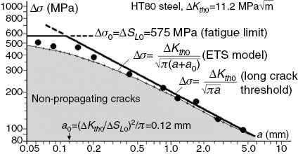
Kitagawa-Takahashi diagram showing the stress ranges Δσ(a) required to propagate fatigue short and long cracks of size a under R=0 in a large HT80 steel plate with ΔKth0=11.2 MPa√m and ΔSL0=575 MPa.
As the generic SIF of cracked structural components is given by KI=σ√(πa)g(a/w), Yu et al. (1988) used the geometry factor g(a/w) to generalize Eq. (2) and redefined the short crack characteristic size by
The largest stress range, Δσ, that does not propagate microcracks in this case is also the fatigue limit, as it should: if a<<a0, ΔKI=ΔKth0⇒Δσ→ΔSL0. However, when the crack starts from a notch, as usual, its driving force is the stress range Δσ at the notch tip, not the nominal stress range Δσn normally used in SIF expressions. Hence, as in such cases the g(a/w) factor includes the stress concentration effect of the notch Kt=σmax/σn, it is better to split it into two parts: g(a/w)=ηφ(a), where φ(a) quantifies the effect of the stress gradient near the notch tip, which for microcracks tends toward Kt, i.e. φ(a→0)→Kt, while the constant η quantifies the effect of the other parameters that affect KI, such as the free surface. In this way, it is better to redefine a0 by:
The stress gradient effect quantified by φ(a) does not affect a0, since the stress ranges at notch tips must be smaller than the fatigue limit to avoid cracking, Δσ(a→0)=Kt Δσn=φ(0)Δσn<ΔSL0. However, since SIFs are crack driving forces, they should be material-independent. Hence, the a0 effect on the short crack behavior should be used to modify FCG thresholds instead of SIFs, making them a function of the crack size, a trick that is quite convenient for operational reasons. In this way, the a0-dependent FCG threshold for pulsating loads ΔKth(a, R=0)=ΔKth0(a) becomes
Note that for large cracks with a>>a0, this short crack FCG threshold tends to ΔKth0, the long crack FCG threshold, and becomes independent of the crack size, as it should. Since Eq. (6) is just one of the models that obey the long and short crack limit behaviors, a data fitting parameter γ proposed by Bazant (1997) may be introduced in it to obtain the minimum stress ranges Δσ0 needed to propagate short or long cracks under pulsating loads as a function of the crack size a:
This γ may allow a better fitting of experimental data, like those collected by Tanaka, Nakai, and Yamashita (1981) and by Livieri and Tovo (2004). Eq. (7) reproduces the original ETS model when γ=2, and the bilinear limits Δσ=ΔSL0 and Δσ=ΔKth0/√(πa), when γ→∞. The curves shown in Figure 4 illustrate the influence of γ on these model predictions.
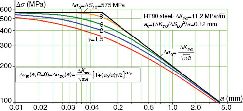
Influence of γ in the fatigue limit curves Δσ0(a) predicted by Eq. (7).
However, as fatigue damage depends on two driving forces, ΔK and Kmax, Eq. (7) should be extended to consider the σmax effect (indirectly modeled by the R ratio) on the short crack behavior. Hence, if ΔKthR=ΔKthR(a>>aR, R) is the FCG threshold for long cracks, ΔSLR=ΔSL(R) is the fatigue limit at the desired R ratio, and aR is the characteristic short crack size at that R, then:
Moreover, unavoidable small defects like inclusions, voids, or scratches may be modeled as mechanically short cracks using LEFM concepts when they are not much smaller than a0. In fact, all structural components should be designed to tolerate such and any other undetectable short cracks. Despite self-evident, this prudent requirement is still not included in most fatigue (let alone in EAC) design routines, which just intend to maintain the service stresses at critical points below their fatigue limits, Δσ<ΔSLR/φF, where φF is a suitable safety factor. Nevertheless, since most long-life designs work well in practice, they certainly are somehow tolerant to undetectable or to functionally admissible short cracks. However, the question “how much tolerant” cannot be answered by the classical SN or εN procedures alone. Such problem can be avoided by adding a tolerance to short crack requirement to their “infinite” life design criteria, which, in its simplest version (the one that deals with constant amplitude loads, those with fixed {Δσ, σmax}), may be given by
Since the fatigue limit ΔSLR already reflects the effect of microstructural defects that are inherent to the material, Eq. (9) complements it by describing the tolerance to cracks of size a (small or not) that may pass unnoticed in actual service conditions. Such estimates can be very useful for designers and quality control engineers. They can be used, e.g. as a quantitative tool to evaluate the effect of an accidental damage on the surface of otherwise well-behaved components.
3 Short crack tolerance under EAC conditions
EAC involves the nucleation and/or the growth of cracks in susceptible materials inside aggressive media under tensile loads. This time-dependent chemical-mechanical damage process may be caused by different mechanisms, but all with a common feature: unlike other corrosion problems, they depend both on the environment-material pair and on the stress state, since cracks cannot grow unless loaded by tensile stresses. So, it can be useful to think that the environment contribution is to decrease the material resistance to the cracking process.
However, for structural design and analysis purposes, most EAC problems have been treated so far by a simplistic overconservative policy on susceptible material-environment pairs: if aggressive media are unavoidable during the service lives, the standard design practice is to choose a material resistant to EAC in such media to build the structural components. A less expensive alternative solution may be to recover the structural component surface with a suitable nobler coating, if such a coating is available. Such overconservative design criteria may be safe, but they can also be too expensive if an otherwise attractive material is summarily disqualified in the design stage when it may suffer EAC in the service environment, without properly considering any stress analysis issues. In fact, the EAC behavior cannot be properly evaluated neglecting the influence of the stress fields that drive them. Decisions based on such an inflexible pass/fail approach may cause severe cost penalties, since no crack can grow unless driven by tensile stresses caused by the service loads and by the residual stresses eventually induced by previous loads and overloads.
In other words, although EAC conditions may be difficult to define in practice due to the number of metallurgical, chemical, and mechanical variables that may affect them, sound structural integrity assessment procedures must include proper stress analysis techniques for calculating maximum tolerable flaw sizes. Such techniques are important in the design stage, but they are even more useful to evaluate operating structural components not originally designed for EAC service, when by any reason they must begin to work under such conditions due to some unavoidable operational change (e.g. a pipeline that must transport originally unforeseen amounts of H2S due to changes in oil well conditions while a new one specifically designed for such service is built and commissioned). Economical pressures to take such a structural risk may be inescapable, since loss of profits associated with the very long time required for replacing the structural component can be huge, especially in offshore applications. Such risky decisions can, in principle, be controlled by the methodology proposed as follows, which extends to EAC problems the analysis developed to mechanically quantify the behavior of short fatigue cracks. Indeed, if cracks behave well under EAC conditions, i.e. if LEFM concepts can be used to properly describe them, then a “short crack characteristic size under EAC conditions” can be defined by (Castro et al., 2015):
So, assuming (as usual) that all chemical effects involved in EAC problems can be appositely described and quantified by the traditional material resistances to crack initiation and propagation under fixed environmental and stress conditions, SEAC and KIEAC, the “short crack characteristic size” a0 concept in EAC follows exactly the same idea of its analogous size so useful for fatigue purposes: it uses the otherwise separated material resistances KIEAC and SEAC to model and predict the behavior of mechanically short cracks and as such can be equally useful in EAC problems. Such resistances are well-defined material properties for a given environment-material pair and can be measured by standard procedures. Moreover, although EAC problems are time dependent, SEAC and KIEAC are not, since they quantify the limit stresses required for starting or for growing cracks under EAC conditions. Hence, supposing that the mechanical parameters that limit EAC damage behave analogously to the equivalent parameters ΔKthR and ΔSLR that limit fatigue damage, a Kitagawa-like diagram can be used as well to quantify the crack sizes a tolerable by any given component that works under fixed EAC and (tensile) stress conditions (see Figure 5).
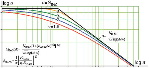
A Kitagawa-Takahashi-like diagram proposed to describe the behavior of short and long cracks under EAC conditions for structural design purposes, using the similitude between the fatigue and EAC problems, assuming that KIEAC is analogous to ΔKthR and that SEAC is analogous to ΔSLR.
This idea can be further expanded. For example, Figure 6 presents an extended Kitagawa-Takahashi diagram that shows four regions that may contain nonpropagating cracks. First, starting from the bottom, the region bounded by the material resistances to crack initiation and large crack growth by fatigue in a given aggressive medium ΔSLR and ΔKthR/√(πa), which limits the tolerance zone that may contain non propagating fatigue cracks in that environment under fixed stress ranges at a given R ratio; second, the region limited by SEAC and KIEAC/√(πa) that may contain nonpropagating cracks by EAC in that medium; third, the crack tolerance region limited by ΔSLvac and ΔKthvac, the R-independent fatigue limit and FCG threshold of the given material in vacuum; and fourth, the region limited by the intrinsic material properties SUvac and KICvac/√(πa), which can be measured only in vacuum or in truly inert environments. The main advantage of looking at this problem in such an integrated way is that it naturally accepts the attempts to treat mechanical and chemical damage under a unified analysis procedure, following, e.g. Vasudevan and Sadananda’s Unified Approach methodologies (Sadananda, 2013; Sadananda & Vasudevan, 2011).
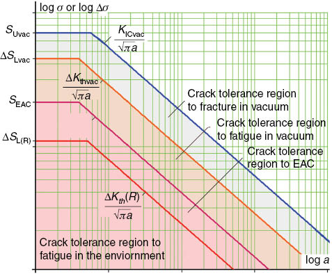
Extended Kitagawa diagram including fatigue and EAC limiting conditions for crack growth.
In other words, if cracks loaded under EAC conditions behave as they should, i.e. if their mechanical driving force is indeed the SIF applied on them; and if the chemical effects that influence their behavior can be described by the material resistance to crack initiation from smooth surfaces quantified by SEAC and by its resistance to crack propagation measured by KIEAC, then it can be expected that cracks induced by EAC may depart from sharp notches and then stop, due to the stress gradient ahead of the notch tips, eventually becoming nonpropagating cracks, exactly as in the fatigue case. In such cases, the size of nonpropagating short cracks can be calculated using the same procedures used for fatigue, and the tolerance to such defects can be properly quantified using a “short crack characteristic size under EAC conditions” in structural integrity assessments. Hence, a criterion for the maximum tolerable stress under EAC conditions can be proposed as
Such equations can be used for stress analyses of notched components under EAC conditions. So, they are potentially useful for structural design purposes when overconservative pass/nonpass criteria used to “solve” most practical SCC problems nowadays are not affordable or cannot be used for any other reason. In fact, they can form the basis for a mechanical criterion for SCC that can be applied even by structural engineers, since it does not require much expertise in chemistry to be useful. Moreover, they can be properly tested, as follows.
4 Verification of the crack-tolerance predictions under LME conditions
To test short crack tolerance predicted by the model proposed here, tests were made first in the Al 2024-liquid gallium pair (Ga is liquid above 30°C), whose main advantage is its very quick LME reactions, in the order of minutes. In comparison, EAC-sensitive Al alloys may take weeks to crack in NaCl-water solutions. Moreover, contrary to other liquid metals that may cause LME, like mercury, Ga is a safe, nontoxic material. LME may occur in solid metal-liquid metal couples that form simple eutectic phase diagrams without any intermetallics (Glickman, 2011; Robertson, 1966). LME leads to low levels of crack nucleation and propagation thresholds, with reported values of KIEAC as low as 0.1 MPa√m and propagation velocity as fast as 0.1 m/s. Whereas EAC in aqueous environment involves metal oxidation at anodic sites and an electrical current flow between anodic and cathodic sites that causes loss of metal and local dissolution at the crack tip, LME does not involve oxidation reactions because the very high electrical conductivity of liquid metals do not allow for separation between locally anodic and cathodic sites.
This 2024 Al alloy was obtained in a T351 temper as a 12.7-mm-thick plate, with analyzed composition Al+4.44Cu-1.35Mg-0.54Mn-0.18Zn-0.16Fe-0.12Si-0.02Cr-0.01Zr in weight percent. However, it had first to be annealed to remove its residual stresses, since in the original as-received plate condition, the Ga environment would induce the test specimens to break during manipulation, spoiling all attempts to properly measure the EAC properties of this pair. All test specimens were cut on the TL direction of the plate, identified by standard metallographic procedures. The basic mechanical properties of the annealed 2024 Al alloy were measured by ASTM E8M procedures at 35°C, resulting in E=70 GPa, SY=113 MPa, SU=240 MPa, and ultimate strain εU=16%.
EAC sensibility and reaction rates of the Al-Ga pair were qualitatively evaluated also at 35°C in very slow dε/dt=4.5×10-8/s strain rate tension tests made in a servo-controlled electromechanical testing machine, following ASTM G129 and NACE recommendations. The liquefied Ga was applied on the test specimen surfaces with a brush, and light bulbs were used to maintain the warm 35°C temperature during the tests. To guarantee that the exposure time was long enough to ensure the full LME reactions, the time necessary to propagate a crack in the annealed Al 2024-liquid Ga pair was double checked by testing precracked C(T) specimens like those used to measure KIEAC. To do so, two precracked specimens were tested under 12 MPa√m and failed in <3 h. Then, two other similar specimens were tested under 7.5 MPa√m and did not fail after 2 days. So, following standard procedures and assuming that the incubation time should be a value close to 3 h, a preload of 7.5 MPa√m was applied for 1 day on the test specimens used to measure KIEAC. Similarly, a preload of 30 MPa was applied for 1 day on the test specimens used to measure SEAC. Then the basic EAC resistances were measured using small incremental load steps induced by calibrated load rings following ASTM E1681, ASTM F1624, and ISO 7539 standard procedures: SEAC tests started at 30 MPa and used 2.5-MPa steps and KIEAC tests initiated at 7.5 MPa√m and used 0.25-MPa√m steps. The time between successive load steps was at least 1 h. The EAC resistances measured by such standard procedures were SEAC=43.6±4.2 MPa (average of nine samples, with 95% reliability) and KIEAC=8.8±0.3 MPa√m (eight samples, 95% reliability).
Finally, using these standard EAC properties, four pairs of C(T)-like notched test specimens were designed to support a maximum local stress σ≅90 MPa>2SEAC at their notch tips. The dimensions chosen for such notches were {b, ρ, b/w}={20 mm, 0.5 mm, 0.33}, {12 mm, 0.5 mm, 0.2}, {20 mm, 0.2 mm, 0.33}, and {40 mm, 4.5 mm, 0.67}, respectively, for specimens called TS1-TS2, TS3-TS4, TS5-TS6, and TS7-TS8, where b and ρ are the notch depth and tip radius and w is the specimen width, with both b and w measured from the load line. The idea was, of course, to study the effect of different combinations of their stress concentration factor Kt and stress gradient ahead of the notch tip in order to ensure tolerance to the short cracks that should start at the tips of their notches, since they all were loaded well above SEAC. The (different) loads applied on each one of such notched test specimens were maintained for at least 48 h, a time much longer than the time required to measure the material resistances to EAC; see Castro et al. (2015) for further details.
Despite being submitted to a much longer exposure than that required to measure SEAC and KIEAC according to standard procedures, none of the designed notched C(T)-like specimens failed during the tests, exactly as predicted (beforehand, during their design stage). Figure 7 shows some of the unbroken notched test specimens after being loaded for a time period 50 times longer than the one required for the standard SEAC measurements by a maximum local stress at the notch tip higher than twice the material resistance to crack initiation under EAC conditions, σmax>2SEAC.
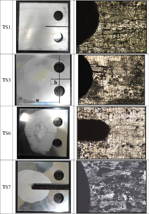
Notched C(T)-like specimens of an annealed Al 2024 alloy after being immersed in liquid Ga for 48 h, a time much longer than the time required to measure the material resistances to EAC, all with width w=60 mm and, from top to bottom, with {b, ρ, b/w}={20 mm, 0.5 mm, 0.33}, {12 mm, 0.5 mm, 0.2}, {20 mm, 0.2 mm, 0.33}, and {40 mm, 4.5 mm, 0.67} after being tested under a peak stress σmax≅90 MPa>2·SSCC at the notch tip, or twice the stress that would lead unnotched specimens to fail by EAC.
Needless to say, since the chance of eight specimens tolerating stresses twice higher than the stress needed to start and propagate cracks in unnotched specimens is very low, this can be seen as a strong experimental evidence that the method proposed here can indeed be useful to evaluate the tolerance to short cracks that depart from notch tips under EAC conditions. However, to double check such predictions, a set of similar tests was made in another material-environment pair, one where the EAC mechanism is completely different, as explained in the sequence.
5 Verification of the crack-tolerance predictions under SSC conditions
SSC was the second EAC mechanism chosen to verify the notch sensitivity effects and the tolerance to short crack predictions made by the model proposed here. SSC is usually accepted to be a form of HE, where the cracking process can be induced by tensile stresses in a susceptible material immersed in an aggressive media containing sufficient amounts of free atomic hydrogen. In the oil and gas industry, in marine applications, and in other organically enriched sediments where the reduction of sulfate ions caused by sulfate-reducing bacteria can produce sufficient H2S, this gas is commonly associated with HE in high-strength low-alloy (HSLA) steels. Known as an acidic gas, the H2S at low pH is stable and can form some acidic solutions after being dissolved in aqueous environments. In particular, the anaerobic corrosion processes typically found in oilfield production occurs as follows:
Anodic reaction:
H2S dissociation reaction:
Cathodic reaction:
Overall reaction:
In this corrosion process, atomic hydrogen (H0) production at local cathodic sites can be seen where it is adsorbed onto the metal surface and forms iron-sulfur compounds with various phases as corrosion products. Different stoichiometric ratios of iron and sulfur produce many solids, including cubic iron sulfide, mackinawite, and troilite (all FeS), pyrite (cubic FeS2), marcasite (FeS2), greigite (Fe3S4), pyrrhotite (Fe1-xS or Fe7S8), and smythite (Fe9S11) (Bai et al., 2014). The atomic hydrogen commonly recombines on the metal surface with another H0 to form hydrogen gas (H2), but the presence of H2S or other sulfur species as dissolved HS- and S-2 can significantly delay that process and increases the atomic hydrogen absorption by the material. This recombination behavior is similar to what happens with other species, such as Sn, Pb, Sb, and P. The main environmental variables associated to SSC in HSLA steels are temperature, pH, and partial pressure of H2S. Low pH normally is more severe than high pH, probably because low pH indicates more hydrogen into the solution. Tests at room temperature are more susceptible to SSC than are tests at relatively high temperature like 200°C, since high partial pressures of H2S increase the susceptibility to SSC (Kane, 1998).
Standard laboratory tests were made with a material previously known to be SSC susceptible, the AISI 4140 steel, to verify whether its crack initiation threshold under SSC conditions was as low enough as in the LME tests made before, say SEAC<SY/2, in order to validate the proposed model predictions by applying a local tensile stress at notch tips about twice as high as SEAC, like in the Al-Ga pair tested before, but maintaining LEFM conditions without failure. The aggressive environment was an aqueous solution containing 5 wt% sodium chloride, 2.5 wt% of glacial acetic acid (CH3COOH), and 0.41 wt% sodium acetate (CH3COONa), referenced as solution B in the NACE TM0177 standard (2005), with pH range 3.4–3.6 at 1 bar total pressure and with a H2S partial pressure of 125 mbar and 875 mbar of CO2 at room temperature. The AISI 4140 steel was received as a round bar, with nominal chemical composition Fe plus 0.8–1.1 Cr, 0.75–1.0 mn, 0.38–0.43 C, 0.15–0.35 Si, 0.15–0.25 mo, 0.04 S max, 0.03 P max in weight percentage. The basic material tensile properties, measured following ASTM E8M standard procedures at 25°C±1°C, were SY=670 MPa and SU=976 MPa.
First, the crack initiation threshold, SEAC, that characterizes the basic resistance of this material-environment pair to SSC or HE conditions was prospected by using small incremental load steps, following ASTM F1624 standard procedures. The test was performed in a servo electromechanical machine following a 10/10/2,4 load profile, with 10 initial load steps of 2 h holding time, followed by 10 load steps of 4 h holding time. The threshold measured with this method was SEAC=332±11.3 MPa. To ensure that the test condition reproduced the same anodic and cathodic reactions described previously, the dissolved oxygen was removed by purging the solution and the test vessel for 2 h per liter with 99,999% pure nitrogen gas before the specimen was immersed into the aggressive solution. As the test vessels must be made from materials that are inert to the test environment, they were manufactured in glass and PTFE (see Figure 8). After the purge, the anaerobic solution was transferred to the test vessel, and the saturation with the test gas was performed for 2 h. After this process, a film developed at the specimen surface and the cathodic reaction could be visualized by the H2 bubbles it produces on the specimen surface (see Figure 9).
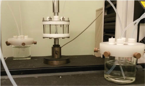
Servo electro-mechanic machine used for the incremental 10/10/2,4 tensile tests; test vessel with a smooth 6.35-mm diameter 4140 steel test specimen used to measure its basic resistance to crack initiation under EAC, SEAC; and the vessels containing the aqueous solution of 5 wt% NaCl, 2.5 wt% CH3COOH, and 0.41 wt% CH3COONa used the aggressive environment for the SCC tests.
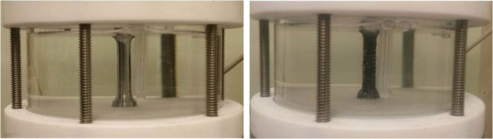
4140 steel specimen immersed into the anaerobic solution after the purge (left) and the same specimen after saturation, showing the cathodic reaction generating H2 bubbles on the specimen surface (right).
The fractographic analyses of the EAC-induced failures in those unnotched tensile specimens in a scanning electron microscope showed a characteristic transgranular cracking behavior, as illustrated in Figure 10.
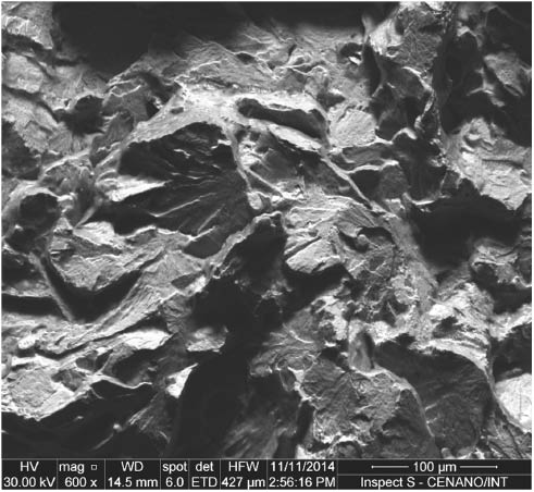
SEM cross-section fractography of the 4140 steel tensile specimen used to measure its SEAC resistance after it was loaded by the 10/10/2,4 profile.
The crack propagation threshold for those SSC conditions was measured using standard NACE TM0177 method D procedures, by testing four side-grooved Double Cantilever Beam specimens machined by wire electrical discharge to avoid residual stresses (see Figure 11). These specimens were immersed in the anaerobic test solution for 14 days and loaded by double tapered wedges in order to provide a crack mouth displacement, δ=0.63 mm, using all precautions adopted in the step loading tests to avoid oxygen contamination. After the test, the specimens were loaded in a servo electro-mechanical machine to obtain the equilibrium wedge-load (P). Finally, the specimens were broken in liquid nitrogen to measure the crack, resulting in KIEAC=34.2 MPa√m (see Figure 12).
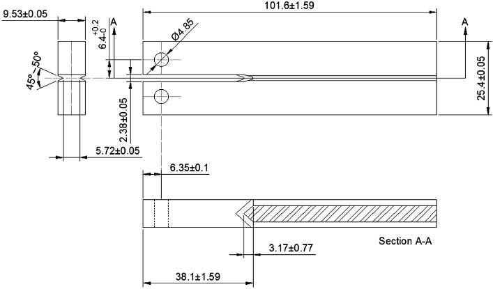
DCB specimens used to measure the basic 4140 resistance to crack propagation under EAC conditions inside the aggressive solution, KIEAC (dimensions in mm).
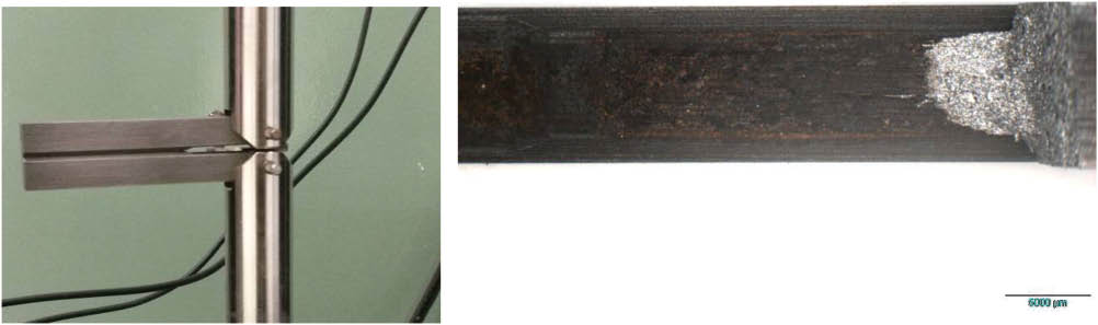
DCB specimen loaded by an imposed displacement in a servo electromechanical testing machine at equilibrium wedge-load (left), before it was immersed in the aggressive solution, and its fracture surface after it was broken in liquid nitrogen (right).
Using the model proposed here and the measured SEAC and KIEAC properties, two notched DC(T)-like specimens were designed and machined with two different notch sizes, to reach at the notch tip a maximum stress near twice the crack initiation threshold SEAC, without exceeding the material yielding strength SY to maintain LE conditions all over the tested specimens. These notched specimen dimensions were width w=60 mm, initial notch size b/w=0.3, and two different notch tip radii, one ρ=0.5 mm and the other ρ=1.5 mm (see Figure 13). Such notched specimens were loaded in proof rings to obtain a maximum stress σmax=610 MPa=1.84·SEAC=0.91·SY at the notch tip. The loads applied by the proof rings were monitored in real time using strain gages (see Figure 14). As shown in Figure 15, exactly as predicted beforehand, these specimens did not broke under such high loads after 30 days of immersion, more than twice the time needed to measure KIEAC.
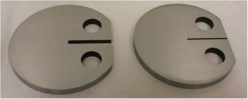
Notched DC(T)-like specimens of 4140 steel before their EAC tests. Note the two different tip radii.
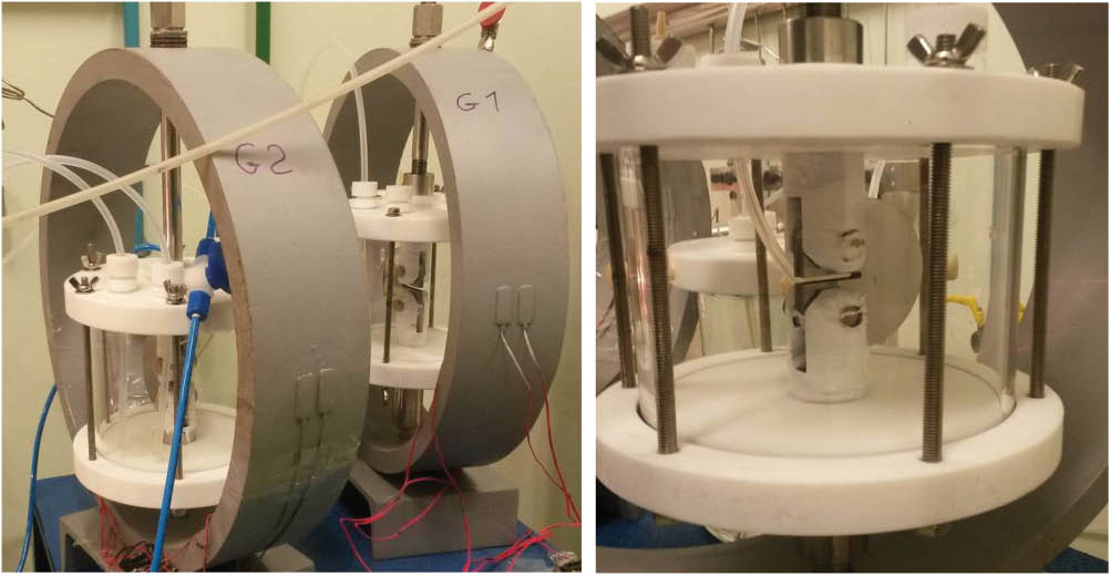
EAC tests of the notched 4140 steel DC(T)-like specimens used to verify the tolerance to short cracks under HE conditions predicted by the model proposed here (right), immersed in the aggressive solution and assembled in proof rings (left), and a front view of one of them.
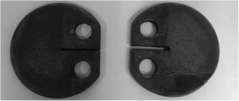
Notched 4140 steel DC(T)-like specimens after their SSC exposition.
Figure 15 shows the two notched DC(T)-like specimens after being exposed during 30 days to the aggressive environment that causes HE in its material. Note once again that although such 4140 steel specimens were loaded to induce a maximum stress at their notch tips σmax=1.84·SEAC, a value much higher than material resistance to start and propagate a crack by EAC in unnotched specimens, they did not break after 30 days immersed in that aggressive environment. Nevertheless, this high stress level did start nonpropagating short cracks at the notch, exactly as predicted by the model proposed here (see Figure 16). This experimental result confirms once again that this mechanical model has the potential to be useful to consider stress analysis issues when analyzing and designing structural components for EAC applications.
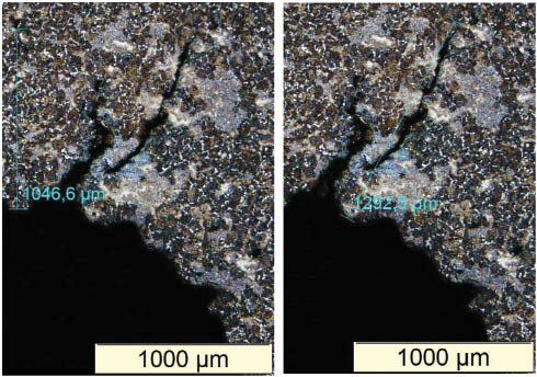
Tip of one of the notched DC(T)-like specimen after the corrosive exposition showing the short cracks that started there but did not propagate even when exposed to a stress σmax=1.84·SEAC during a time more than twice longer than the one needed to measure the EAC crack propagation threshold by standard procedures, exactly as predicted by the model proposed here.
6 Additional comments
Before closing this work, it must be emphasized that the predictions made here complement the most important contributions of previous pioneer research on crack tolerance under EAC conditions, e.g. those presented in the classic work of Parkins (1979) on the effect of slow strain-rate tests on the EAC behavior. These early works clearly identified the existence of a crack propagation threshold under EAC conditions, so in a sense, they can be used to evaluate the stresses tolerable by cracked components.
However, this classic concept is directly applicable only to long cracks, those that are not affected by stress gradients induced by notches. Moreover, if the crack itself is induced by EAC mechanisms, it is sensitive to the maximum tensile stress at its initiation point, which of course must be higher than the minimum stress level required to start it, σ>SEAC. If the SIF KI of such a crack increases with its size a, the usual case if it departs from a smooth surface and if the cracked component is loaded by an imposed (constant) load, then the initiated crack can propagate until the final fracture of the component. Note that under imposed displacements, like in the DCD specimens used to measure the 4140 steel KIEAC value under SCC conditions as described above, the crack can stop (and thus become a nonpropagating crack) because its SIF decreases as it grows until reaching the arrest condition KI(a)<KIEAC. But since many, if not most, components work under fixed loads, thus having KI(a) values that increase with a, the only safe procedure recognized so far to avoid their failures under EAC conditions is to limit their maximum stresses to values below their crack initiation threshold, σmax<SEAC.
If the resistance to crack initiation under EAC conditions, SEAC, is relatively low, say smaller than the material yield limit, then the only choice to avoid such failures indeed seems to be to change the material for a more resistant one. However, from the point of view of a structural engineer, this criterion has a major setback: the stress concentration effects induced by operational or accidental notches, which are unavoidable in practice. As the maximum stress at those notch tips can be much higher than the nominal stresses that act elsewhere in the component, they control the EAC failures, and if its material is sensible to EAC inside its working environment, the need to change it seems inevitable.
This problem can lead to expensive solutions in the design stage (e.g. the use of super duplex stainless steel for sensitive pipelines in the oil industry), but it is not a major barrier in such cases. The real trouble is with unforeseen problems as mentioned before: how to decide what to do with an already built and operating structure in such cases. If the problem is discovered before the structure fails and obviously is still safe, how much safe is it? For how long can it continue operating under the service loads within an acceptable risk level? There is simply no way to answer such and similar questions without a proper stress analysis procedure, one that properly considers the unavoidable notch effects. That is the main contribution of Eq. (11), which properly considers the notch sensitivity under EAC conditions. Note that although its deduction has been purely mechanical, and because of that it may seem a little bit strange to those more trained in chemical than in mechanical techniques, its predictions that notch tips could tolerate stresses much higher than SEAC have been confirmed by two sets of discriminating tests made inside aggressive media that induced different EAC mechanisms. Besides, the model considers the chemical contribution to the EAC problems by using the resistances to crack initiation and growth inside the aggressive environment, properties traditionally recognized to properly quantify these chemical effects. So, albeit the tests presented here are certainly not enough to claim that this model should be included in structural evaluations routines, the authors believe that it has potential to be really useful in such situations, and thus deserve to be further studied.
Finally, some words of caution. Microstructurally short cracks, those small compared to the grain size gr, are much affected by microstructural barriers like grain boundaries or 2nd phase particles, so they cannot be well modeled by macroscopic stress analysis techniques. Their behavior can be academically important, but as such microscopic cracks cannot be mapped in most practical applications, they are not part of this work scope. On the other hand, mechanically short cracks, which have sizes that are not small compared to the grain size and, as depicted in the Kitagawa-like diagram, have thresholds smaller than ΔKIEAC, can be properly modeled by LEFM concepts (i) if the stress field that surrounds them is predominantly LE and (ii) if the material can be treated as isotropic and homogeneous in this scale, both qualitative conditions. Hence, the idea here was to follow Irwin’s steps by first assuming that these concepts are valid and then by verifying whether their predictions are validated by proper tests. The several tests made under LE peak stresses at the notch tips inside the two environments that induced totally different EAC mechanisms supported the model predictions, but their limitations have not been checked yet. Indeed, the model developed and used in this work assumes that the crack effects can be properly quantified by their SIFs, a hypothesis that must be reviewed if they grow through predominantly plastic stress fields, those associated to plastic zones that are not much smaller than the residual uncracked ligament. The model also assumes that the short cracks grow unidimensionally, so they can be properly characterized by its size, a, only. However, when the surface flaws are much smaller than the piece dimensions, they probably look like small surface or corner cracks and should be treated as so, recognizing that they are 2D cracks that grow in two directions, usually changing their shape as they propagate, although maintaining their original plane under mode I loads. Anyway, even though these model limitations must be explored in complementary works, they do not invalidate the main contribution proposed in this work: the existence of a clearly definable notch sensitivity factor that can be used to introduce proper stress analysis tools for EAC structural integrity evaluation and design purposes.
7 Conclusions
A generalized ETS parameter was used to model the dependence of the threshold stress intensity range for short fatigue cracks on the crack size, as well as the behavior of nonpropagating cracks induced by tensile stresses under EAC conditions. This dependence was used to estimate the notch sensitivity factor of shallow and elongated notches both for fatigue and for EAC conditions, from the propagation behavior of short nonpropagating cracks that might initiate from their tips, and then stopped due to the high-stress gradients that may act ahead of the notch tips. As made for the fatigue case before, these predictions were verified by proper experiments for two different EAC mechanisms, LME and HE. Based on this promising performance, the criterion proposed to evaluate the influence of small or large surface flaws in fatigue and in EAC problems may be useful for practical applications and deserves further attention.
Acknowledgments
The Brazilian Research Council (CNPq) has provided research scholarships for some of the authors; Dr. A. Vasudevan, formerly from the Office of Naval Research of the US Navy (ONR), has contributed with many stimulating discussions; and ONR has provided a grant to partially support this research, through the supervision of Dr. W. Nickerson (grant/award number: ONRG-NICOP-N62909-15-1-N160).
References
Atzori B, Lazzarin P, Filippi S. Cracks and notches: analogies and differences of the relevant stress distributions and practical consequences in fatigue limit predictions. Int J Fatigue 2001; 23: 355–362.10.1016/S0142-1123(00)00107-9Search in Google Scholar
Atzori B, Lazzarin P, Meneghetti G. Fracture mechanics and notch sensitivity. Fatigue Fract Eng Mater Struct 2003; 26: 257–267.10.1046/j.1460-2695.2003.00633.xSearch in Google Scholar
Atzori B, Lazzarin P, Meneghetti G. A unified treatment of the mode I fatigue limit of components containing notches or defects. Int J Fract 2005; 133: 61–87.10.1007/s10704-005-2183-0Search in Google Scholar
Atzori B, Meneghetti G, Susmel L. Material fatigue properties for assessing mechanical components weakened by notches and defects. Fatigue Fract Eng Mater Struct 2005; 28: 83–97.10.1111/j.1460-2695.2004.00862.xSearch in Google Scholar
Bai P, Zheng S, Zhao H, Ding Y, Wu J, Chen C. Investigations of the diverse corrosion products on steel in a hydrogen sulfide environment. Corros Sci 2014; 87: 397–406.10.1016/j.corsci.2014.06.048Search in Google Scholar
Bazant ZP. Scaling of quasibrittle fracture: asymptotic analysis. Int J Fract 1997; 83: 19–40.10.1023/A:1007387823522Search in Google Scholar
Bertness TA, Chilingarian GV, Al-Bassam M. Corrosion in drilling and producing operations. In: Chilingarian GV, Robertson JO, Kumar S, editors. Developments in petroleum science v.19B, Oxford, UK: Elsevier, 1989: 283–317.10.1016/S0376-7361(08)70507-7Search in Google Scholar
Castro JTP, Leite JCC. Does notch sensibility exist in environmentally assisted cracking (EAC)? J Mat Res Technol 2013; 2: 288–295.10.1016/j.jmrt.2013.02.010Search in Google Scholar
Castro JTP, Meggiolaro MA. Is notch sensitivity a stress analysis problem? Frattura ed Integrità Strutturale 2013; 25: 79–86.10.3221/IGF-ESIS.25.12Search in Google Scholar
Castro JTP, Meggiolaro MA. On the tolerance to short cracks under fatigue and SCC conditions. Procedia Eng 2014; 74: 242–245.10.1016/j.proeng.2014.06.256Search in Google Scholar
Castro JTP, Meggiolaro MA. Fatigue design techniques vol III–crack propagation, thermal and statistical effects. CA, USA: Create Space, 2015.Search in Google Scholar
Castro JTP, Meggiolaro MA, Miranda ACO, Wu H, Imad A, Nouredine B. Prediction of fatigue crack initiation lives at elongated notch roots using short crack concepts. Int J Fatigue 2012; 42: 172–182.10.1016/j.ijfatigue.2011.10.010Search in Google Scholar
Castro JTP, Landim RV, Leite JCC, Meggiolaro, MA. Prediction of notch sensitivity effects in fatigue and EAC. Fatigue Fract Eng Mater Struct 2015; 38:161–179.10.1111/ffe.12156Search in Google Scholar
Chapetti MD. Fatigue propagation threshold of short cracks under constant amplitude loading. Int J Fatigue 2003; 25: 1319–1326.10.1016/S0142-1123(03)00065-3Search in Google Scholar
Chapetti MD. Fatigue assessment using an integrated threshold curve method–applications. Eng Fract Mech 2008; 75: 1854–1863.10.1016/j.engfracmech.2006.11.005Search in Google Scholar
Ciavarella M, Meneghetti G. On fatigue limit in the presence of notches: classical vs. recent unified formulations. Int J Fatigue 2004; 26: 289–298.10.1016/S0142-1123(03)00106-3Search in Google Scholar
Cramer SD, Covino BS Jr, editors. Corrosion: fundamentals, testing, and protection, ASM handbook v.13A. Materials Park, OH, USA: ASM International, 2003.10.31399/asm.hb.v13a.9781627081825Search in Google Scholar
Dietzel W. Fracture mechanics approach to stress corrosion cracking. Anales de Mecánica de la Fractura 2001; 18: 1–7.Search in Google Scholar
Dixon WJ. The up-and-down method for small samples. Am Stat Assoc J 1965; 60: 967–978.10.1080/01621459.1965.10480843Search in Google Scholar
Du Quesnay DL, Yu MT, Topper TH. An analysis of notch-size effects at the fatigue limit. J Test Eval 1988; 16: 375–385.10.1520/JTE11081JSearch in Google Scholar
El Haddad MH, Smith KN, Topper TH. Fatigue crack propagation of short cracks. J Eng Mater Technol 1979; 101: 42–46.10.1115/1.3443647Search in Google Scholar
El Haddad MH, Topper TH, Smith KN. Prediction of non-propagating cracks. Eng Fract Mech 1979; 11: 573–584.10.1016/0013-7944(79)90081-XSearch in Google Scholar
Fontana MG. Corrosion engineering. New York, NY, USA: McGraw Hill Book Co., 1986.Search in Google Scholar
Glickman EE. Dissolution condensation mechanism of stress corrosion cracking in liquid metals: driving force and crack kinetics. Metall Mater Trans A 2011; 42: 250–266.10.1007/s11661-010-0429-6Search in Google Scholar
Kane RD. Roles of H2S in the behavior of engineering alloys: a review of literature and experience: NACE International Conference, Paper, San Diego, CA, USA, 274, 1998.10.5006/C1998-98274Search in Google Scholar
Kitagawa H, Takahashi S. Applicability of fracture mechanics to very small crack or cracks in the early stage. Second International Conference on Mechanical Behavior of Materials, Boston, MA, 1976: 627–631.Search in Google Scholar
Korb LJ, Olson DL, editors. Corrosion, ASM handbook v.13. ASM, 1992.Search in Google Scholar
Krupp U, Düber O, Christ HJ, Künkler B, Schick A, Fritzen CP. Application of the EBSD technique to describe the initiation and growth behaviour of microstructurally short fatigue cracks in a duplex steel. J Microsc 2004; 213: 313–320.10.1111/j.0022-2720.2004.01306.xSearch in Google Scholar PubMed
Lawson L, Chen EY, Meshii M. Near-threshold fatigue: a review. Int J Fatigue 1999; 21: S15–S34.10.1016/S0142-1123(99)00053-5Search in Google Scholar
Leis BN, Eiber RJ. Stress-corrosion cracking on gas-transmission pipelines: history, causes, and mitigation. Proceedings of the First International Conference on Onshore Pipelines, Berlin, 1997.Search in Google Scholar
Lin SK, Lee YL, Lu MW. Evaluation of the staircase and the accelerated test methods for fatigue limit distributions. Int J Fatigue 2011; 23: 75–83.10.1016/S0142-1123(00)00039-6Search in Google Scholar
Lisagor WB. Environmental cracking–stress corrosion. ASTM corrosion tests and standards–interpretation and application (manual 20). ASTM, 2005.Search in Google Scholar
Livieri P, Tovo R. Fatigue limit evaluation of notches, small cracks and defects: an engineering approach. Fatigue Fract Eng Mater Struct 2004; 27: 1037–1049.10.1111/j.1460-2695.2004.00816.xSearch in Google Scholar
Lorenzino P, Navarro A. Initiation and growth behaviour of very-long microstucturally short fatigue cracks. Frattura ed Integrità Strutturale 2013; 25: 138–144.10.3221/IGF-ESIS.25.20Search in Google Scholar
Lynch SP. Failures of engineering components due to environmentally assisted cracking. Pract Fail Anal 2003; 3: 33–42.10.1361/152981503771816754Search in Google Scholar
McEvily AJ. The growth of short fatigue cracks: a review. Mater Sci Res Int 1988; 4: 3–11.Search in Google Scholar
McEvily AJ, Wei RP. Fracture mechanics and corrosion fatigue. In: Proceedings of the International Conference on Corrosion fatigue: Chemistry, mechanics and microstructure. Houston, Texas: NACE, 1972: 381–395.Search in Google Scholar
Meggiolaro MA, Miranda ACO, Castro JTP. Short crack threshold estimates to predict notch sensitivity factors in fatigue. Int J Fatigue 2007; 29:2022–2031.10.1016/j.ijfatigue.2007.02.022Search in Google Scholar
NACE TM0177. Laboratory testing of metals for resistance to sulfide stress cracking and stress corrosion cracking in H2S environments. Texas, USA: NACE International, 2005.Search in Google Scholar
Navarro A, de los Rios ER. A microstructurally-short fatigue crack growth equation. Fatigue Fract Eng Mater Struct 1988; 5: 383–396.10.1111/j.1460-2695.1988.tb01391.xSearch in Google Scholar
Parkins RN. Development of strain-rate testing and its implications. In: Ugiansky GM, Payer JH, editors. ASTM STP 665, stress corrosion cracking–the slow strain-rate technique. Symposium was held 2–4 May 1977 in Toronto, Canada. Philadelphia, PA, USA: American society for testing and materials, ASTM, 1979: 5–25.10.1520/STP38106SSearch in Google Scholar
Robertson WM. Propagation of a crack filled with liquid metal. Trans Metall Soc AIME 1966; 236: 1478–1482.Search in Google Scholar
Sadananda K. Failure diagram and chemical driving forces for subcritical crack growth. Metall Mater Trans A 2013; 44: 1190–1199.10.1007/s11661-012-1469-xSearch in Google Scholar
Sadananda K, Vasudevan AK. Short crack growth and internal stresses. Int J Fatigue 1997; 19: S99–S108.10.1016/S0142-1123(97)00057-1Search in Google Scholar
Sadananda K, Vasudevan AK. Failure diagram for chemically assisted crack. Metall Mater Trans A 2011; 42: 296–303.10.1007/s11661-010-0469-ySearch in Google Scholar
Tanaka K, Nakai Y, Yamashita M. Fatigue growth threshold of small cracks. Int J Fract 1981; 17: 519–533.10.1007/BF00033345Search in Google Scholar
Vallellano C, Navarro A, Dominguez J. Fatigue crack growth threshold conditions at notches. Part I: theory. Fatigue Fract Eng Mater Struct 2000; 23: 113–121.10.1046/j.1460-2695.2000.00257.xSearch in Google Scholar
Vasudevan AK, Sadananda K. Classification of environmentally assisted fatigue crack growth behavior. Int J Fatigue 2009; 31: 1696–1708.10.1016/j.ijfatigue.2009.03.019Search in Google Scholar
Vasudevan AK, Sadananda K. Review of environmentally assisted cracking. Metall Mater Transact A 2011a; 42A: 279–295.10.1007/s11661-010-0472-3Search in Google Scholar
Vasudevan AK, Sadananda K. Role of internal stresses on the incubation times during stress corrosion cracking. Metall Mater Transact A 2011b; 42A: 396–404.10.1007/s11661-010-0470-5Search in Google Scholar
Vasudevan AK, Sadananda K. Role of slip mode on stress corrosion cracking behavior. Metall Mater Transact A 2011c; 42A: 405–414.10.1007/s11661-010-0471-4Search in Google Scholar
Verreman Y. Propagation des fissures curtes. In: Bathias C, Pineau A, editors. Fatigue des Máteriaux et Structures 2. Hermes-Lavoisier, 2008.Search in Google Scholar
Wu H, Imad A, Nouredine B, Castro JTP, Meggiolaro MA. On the prediction of the residual fatigue life of cracked structures repaired by the stop-hole method. Int J Fatigue 2010; 32: 670–677.10.1016/j.ijfatigue.2009.09.011Search in Google Scholar
Yu MT, Duquesnay DL, Topper TH. Notch fatigue behavior of 1045 steel. Int J Fatigue 1988; 10: 109–116.10.1016/0142-1123(88)90038-2Search in Google Scholar
©2015 by De Gruyter
Articles in the same Issue
- Frontmatter
- In this issue
- Editorial
- International Symposium on Environmental Damage Under Static and Cyclic Loads in Structural Metallic Materials at Ambient Temperatures III (Bergamo, Italy, June 15–20, 2014)
- Overviews and reviews
- U.S. Naval Aviation: operational airframe experience with combined environmental and mechanical loading
- Thirty-five years in environmentally assisted cracking in Italy: a point of view
- Fatigue and corrosion fatigue
- Transgranular corrosion fatigue crack growth in age-hardened Al-Zn-Mg (-Cu) alloys
- Effect of cyclic frequency on fracture mode transitions during corrosion fatigue cracking of an Al-Zn-Mg-Cu alloy
- Crack growth behavior of 4340 steel under corrosion and corrosion fatigue conditions
- Modeling of environmentally assisted fatigue crack growth behavior
- Factors influencing embrittlement and environmental fracture
- Pre-exposure embrittlement of an Al-Cu-Mg alloy, AA2024-T351
- Electrochemical approach to repassivation kinetics of Al alloys: gaining insight into environmentally assisted cracking
- Localized dissolution of grain boundary T1 precipitates in Al-3Cu-2Li
- Grain boundary anodic phases affecting environmental damage
- Defect tolerance under environmentally assisted cracking conditions
- Role of Mo/V carbides in hydrogen embrittlement of tempered martensitic steel
- Stress corrosion cracking
- The role of crack branching in stress corrosion cracking of aluminium alloys
- An atomistically informed energy-based theory of environmentally assisted failure
- Discrete dislocation modeling of stress corrosion cracking in an iron
- Quasi-static behavior of notched Ti-6Al-4V specimens in water-methanol solution
- Role of excessive vacancies in transgranular stress corrosion cracking of pure copper
- Multiscale investigation of stress-corrosion crack propagation mechanisms in oxide glasses
- Hydrogen assisted cracking
- Hydrogen effects on fracture of high-strength steels with different micro-alloying
- Environmentally assisted cracking and hydrogen diffusion in traditional and high-strength pipeline steels
- Multiscale thermodynamic analysis on hydrogen-induced intergranular cracking in an alloy steel with segregated solutes