
Pre-exposure embrittlement of an Al-Cu-Mg alloy, AA2024-T351
-
N.J. Henry Holroyd
N.J. Henry Holroyd is a self-employed consultant retained by several clients and an Adjunct Professor with Case Western Reserve University, Cleveland, Ohio, having previously been Senior Vice President of Luxfer Gas Cylinders with global responsibility for Technology and Innovation and a visiting Professor at several UK Universities. Has published well over 100 scientific papers, mainly on the localized corrosion and environment-assisted-cracking of higher-strength aluminium alloys, and is the first named inventor on 7 granted globally patents associated with aluminium alloy usage in metal-spray coatings, welding technology and pressure vessel technology. Hobbies include: playing tenor saxophone (mainstream jazz), golf and collecting/appreciating fine wine.
 ,
J.T. Evans
,
J.T. Evans
J.T. Evans is Emeritus Professor at the University of Newcastle upon Tyne and was previously head of the Department of Mechanical, Materials and Manufacturing Engineering. He has extensive publications in the following areas: Dislocations and Plastic Flow in Metals and Alloys; Fracture and Sub-critical Crack Growth in Metals and Composites; Residual Stresses, Fatigue and Surface Contact Fatigue in Gearing; Design and Performance of Carbon-Fibre Composites and Fire-resistance of Carbon-fibre Composites. Included in his most recent publication is work on Magnetism and Barkhausen Emission in Ferromagnetic Materials.
Geoffrey M. Scamans is the Chief Scientific Officer at Innoval Technology and is a Professor of Metallurgy at Brunel University. His expertise is in light metals and their applications in the automotive and aerospace industries, and in knowledge transfer from the research base to industry. Over the last 40 years he has initiated and managed a number of R&D programmes on both materials development and technological innovation, making scientific and technological contributions to the light metals sector, described in over 150 publications. His main interests are in the closed loop recycling of aluminium alloys as an alternative to primary production in order to transform the aluminium industry from packaging based products into transport based products (“Cans to Car”). His other main interest is in understanding the development and properties of deformed surface layers on aluminium alloys and their control through efficient cleaning and pretreatment processes to increase line speeds in sheet finishing operations and to eliminate cosmetic corrosion.

Abstract
When Al-Cu-Mg (AA2024-T351) alloy plate is immersed in 0.53 m NaCl solution, intergranular corrosion occurs, which initially takes the form of narrow fissures at the surface. Although growth of these fissures is initially rapid, it soon slows and the penetration depth is limited. However, these intergranular fissures can give rise to intergranular subcritical crack growth and eventual catastrophic fracture if specimens are strained slowly in laboratory air after pre-exposure to the NaCl solution. In our experiments, tensile specimens of the alloy were strained at strain rates in the range 10-7–10-4/s, and the cracking propensity was found to increase with pre-exposure times up to around 300 h. However, cracking was much reduced with longer pre-exposure times and became negligible after 500 h. This rather unexpected result can be explained by the observation that the intergranular corrosion fissure becomes increasingly broad and un-crack-like with extended pre-exposure times, failing to meet the prerequisite initiation conditions required for intergranular stress corrosion cracking. A further unexpected result was that straining specimens in the same 0.53 m NaCl solution after pre-exposure produced no intergranular crack growth. To investigate this further, tensile tests were conducted under electrochemical control, and this showed that the free corrosion potential in the test solution was too low in 0.53 m NaCl to allow cracking to proceed.
1 Introduction
Although stress corrosion cracking (SCC) in Al-Cu and Al-Cu-Mg alloys has been studied for over 90 years (Blain, Masounave, & Dickinson, 1984; Branco, Radon, & Culver, 1977; Braun, 1993; Colner & Francis, 1958; Dietzel, Schwalbe, & Wu, 1989; Dix, 1940; Farmery & Evans, 1955–56; Garner & Tromans, 1979; Izumoto & Nishimura, 2011; Ketchem, 1967; Lee, Kim, Jeong, & Kim, 2012; Little, Connolly, & Scully, 2007; Liu, Frankel, Zoofan, & Rokhlin, 2007; Logan & Hessing, 1948; Maitra, 1981; Mears, Brown, & Dix, 1945; Rawdon, Krynitsky, & Berliner, 1922; Reboul, Magnin, & Warner, 1992; Sprowls & Brown, 1969; Sugimoto, Hoshino, Kageyama, Kageyama, & Sawada, 1975; Urshino & Sugimoto, 1979), neither crack initiation nor the transition from intergranular corrosion (IGC) to intergranular stress corrosion cracking (IGSCC) is fully understood. A number of experimental studies of the early stages of localized corrosion of the Al-Cu-Mg alloy AA2024 have been published recently (Boag, Hughes, Glenn, Muster, & McCulloch, 2011; DeRose et al., 2012; Glenn et al., 2011; Hughes, Parvizi, & Forsyth, 2015; Hughes et al., 2011; King, Cole, Corrigan, Hughes, & Muster, 2011; Knight, Salagaras, & Trueman, 2011; Liu, Frankel, Zoofan, & Rokhlin, 2006; Luo, Zhou, Thompson, & Hughes, 2012; Malladi et al., 2013; Zang & Frankel, 2003; Zhou, Luo, Hashimoto, Hughes, & Thompson, 2012; Zhou et al., 2013) based on the use of advanced imaging techniques such as high-resolution electron microscopy, X-ray tomography, 3D imaging using low-voltage scanning electron microscopy combined with serial sectioning using ultramicrotomy, and local electrochemical measurements. This work coupled with mathematical modelling (Abodi et al., 2012; Xiao & Chauduri, 2011) has demonstrated the initiation of localized attack at primary intermetallic particles and the development of stable pits if a continuity of available cathodic particles is maintained by subsurface clusters of intermetallic particles. Once an occluded cell has developed and a local acidified chemistry has been established, then IGC is initiated and may grow back to the external surface to form an intergranular trench. The direct surface initiation of intergranular attack is not usually seen unless the electrolyte is acidified or attack is stimulated by anodic polarization. The IGC penetrates along grain boundaries as a narrow crevice. Attack occurs in one of the two grains that form the boundary but not in the second grain, and this has been correlated with the dislocation density (stored energy) of the corroded grain.
The conventional view is that IGSCC occurs under anodic dissolution control (Dix, 1940; Garner & Tromans, 1979; Little et al., 2007; Liu et al., 2007; Reboul et al., 1992; Sprowls & Brown, 1969; Sugimoto et al., 1975; Urshino & Sugimoto, 1979), but more recent experimental findings have suggested a potential role for hydrogen embrittlement (Hardwick, Taheri, Thompson, & Bernstein, 1982; Lee et al., 2012; Moran & Stoner, 1988), especially if alloys are pre-charged with hydrogen (Hardwick et al., 1982) or electrochemical potentials during straining are held at cathodic potentials below the free corrosion potential (Lee et al., 2012).
It has been found that SCC testing smooth specimens in aqueous sodium chloride under alternate immersion (wet-dry conditions, e.g. ASTM G44) readily produces crack initiation (Newton & Holroyd, 1992; Sprowls & Brown, 1969), whereas under total immersion conditions, initiation is rare without an additional stimulus such as electrochemical polarization (Lee et al., 2012) or addition of hydrogen peroxide (Holroyd & Scamans, 1984). Farmery and Evans (1955–56) observed IGSCC initiation and test failures within 30 min when as-received surface oxide films were removed (by immersion in concentrated sodium hydroxide followed by dilute nitric acid to remove a blackish film left behind by the alkali) just before application of a constant load (95% yield stress) to an under-aged Al-4%Cu alloy totally immersed in 0.5 m NaCl. No failure or long failure times resulted when as-received surface layers remained intact prior to load application.
The sensitivity of initiation in IGSCC to the prevailing environmental conditions may account for the fact that contradictory results for SCC susceptibility in commercial 2xxx series alloys frequently result for similar test methods (Hyatt, 1970; Mulherin, 1967; Sprowls, 1967; Ugiansky, Johnson, Thompson, & Gillespie, 1979).
In this paper, we present results showing that pre-exposure of an Al-Cu-Mg alloy (AA2024-T351) to 0.53 m NaCl leads to IGSCC initiation and propagation during subsequent slow strain rate testing in laboratory air but not while immersed in aqueous NaCl at the free corrosion potential. This is complicated behavior, but we develop a rationale for it, which may also help account other reported anomalies in IGSCC behavior.
In this paper, we first present results showing the pronouncedly different effects of environments on SCC after specimens had been pre-exposed in a NaCl solution. We then present results to show that the most damaging effects of pre-exposure can be negated by holding specimens in air for an extended period after pre-exposure but before tensile testing. So far, the results might suggest that hydrogen embrittlement is involved. However, we rule this out for several reasons. A strong link between the depth of IGC and the subsequent depth of total cracking is demonstrated, and it is also demonstrated that uninterrupted immersion in NaCl (pre-exposure in NaCl followed by testing in NaCl) is ineffective in producing SCC. We then demonstrate that the ineffectiveness of uninterrupted immersion is entirely due to the effect of electrochemical potential: specimens tested with uninterrupted immersion are cathodically protected at the free corrosion potential in NaCl. It is concluded that the tests performed in laboratory air after pre-exposure are effective in producing SCC because IGC produces a local environment within the IGC defect that is favorable to IGSCC. The results are discussed with reference examples of supporting evidence in the literature.
2 Materials and methods
2.1 Materials
The alloy selected for testing was a commercial Al-Cu-Mg alloy, AA2024, containing (wt. %) 4.1 Cu, 1.3 Mg, 0.05 Zn, 0.22 Fe, 0.09 Si, and 0.53 Mn supplied in the form of 35-mm-thick rolled plate in the T351 condition [0.2% yield stress 340 MPa, ultimate tensile strength (UTS) 425 MPa, K1c (ST) 18 MNm-3/2] with a typical fibrous “pancake” grain microstructure.
For slow strain rate testing, smooth tensile specimens with a gauge length and diameter of 11.5 and 3.2 mm, respectively, had radii of 1.6 mm at the ends of the gauge length leading to 4.5 mm long screwed ends for attachment to special grips (detailed design details given elsewhere; Holroyd & Hardie, 1981). Tensile test specimens were machined with their major axis parallel to the short-transverse direction in order to maximize susceptibility to IGSCC.
2.2 Pre-exposure and tensile testing
To examine the effect of pre-exposure, the tensile specimen gauge lengths were mechanically polished to 3/0 emery paper (soaked in liquid paraffin oil) and ultrasonically degreased in acetone for lengthy periods to ensure the generation of oil-free surfaces. Specimens were then totally immersed in 0.5 l of naturally aerated 0.53 m NaCl made up using analytic reagent grade sodium chloride and deionized water. All experiments were conducted at 22±2°C using pre-exposure times up to 30 days.
Slow strain rate testing after pre-exposure was, in general, conducted at the nominal strain rate of ~10-5/s. However, to study the influence of strain rate, some testing was done using strain rates in the range 10-7 to 5×10⁻⁵/s. The applied force was monitored via a load cell during the tests and recorded as a function of time. Because the cross-head displacement rate is constant, the force-time record is an accurate proxy for the force-displacement record. Generally, fracture occurred without much evidence of necking.
Tensile tests were carried out with specimens exposed to three test environments. These were as follows: (i) laboratory air (relative humidity 58–60%), (ii) dry air (anhydrous magnesium perchlorate granules packed around the specimen), and (iii) total immersion in 0.53 m NaCl. Surface films produced during the pre-exposure were not removed prior to testing except in certain specific instances where the specimen gauge lengths were given a light mechanical polish to 3/0 emery paper (soaked in liquid paraffin oil) to remove any visible evidence of IGC in the surface layers and then ultrasonically degreased in acetone. After pre-exposure, samples were removed from the saline solution, immediately given a gentle rinse with a small volume of distilled water, and then exposed to laboratory air for no more than 10 min prior to the application of load during subsequent slow strain rate testing.
In some instances, electrochemical potentials were measured during tensile testing relative to the saturated calomel electrode (SCE). In addition to conducting slow strain rate testing in 0.53 m NaCl at the free corrosion potential, further testing was carried out with electrochemical potentials held potentiostatically in the range -0.850 to -0.500 V (SCE).
Fracture surfaces were examined using a scanning electron microscope.
3 Results
3.1 Effect of test environment on peak stress
Because very little necking occurred in the tensile tests, the peak stress can be considered as the fracture stress. Even though slow fracture in the form of crack nucleation and growth may have occurred before the peak load, the peak stress is where the fracture becomes unstable and is determined by the fracture toughness of the material. The observed peak stresses as a function of pre-exposure time are shown in Figure 1. Note that although all the specimens were pre-exposed, only the specimens tested in laboratory air show a significant effect of pre-exposure for pre-exposure times up to 300 h. Specimens tested in dry air show much less reduction in peak stress with pre-exposure time. Surprisingly, specimens exposed in NaCl solution and then strained in the same solution show hardly any loss of strength. Equally surprising was the fact that the strength-reducing effect of straining in laboratory air had all but disappeared when specimens were pre-exposed for longer than about 450 h.
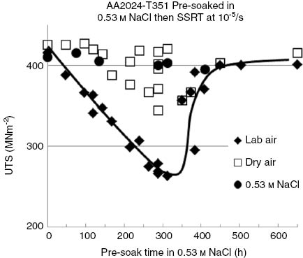
The effect of pre-exposure on peak stress (UTS) for specimens strained slowly in either laboratory air, dry air, or strained while immersed in the pre-exposing solution itself. Tensile specimens were produced from AA2024-T351 alloy as described in the text, and they were pre-exposed to 0.53 m NaCl.
Fractures produced in laboratory air displayed a well-defined outer peripheral ring of embrittlement (as shown in Figure 2), which increased in depth with pre-exposure times up to about 300 h and then decreased rapidly with further pre-exposure such that after 500 h, little embrittlement was evident in the fracture surfaces.
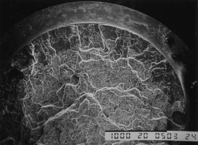
Characteristic external peripheral ring of intergranular fracture for AA2024-T351 tensile specimens pre-exposed to 0.53 m NaCl for times up to 300 h prior to slow strain rate testing to failure at a nominal strain rate of 10-5/s while exposed to laboratory air.
As shown in Figure 1, pre-exposure for 288 h produced the greatest loss in peak stress for the specimens tested in air. However, if specimens were pre-exposed for this time and then left to stand in laboratory air for various times up to 200 h, then the damage produced by the pre-exposure was progressively reduced (Figure 3).
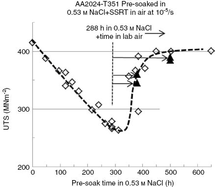
Influence of holding pre-exposed AA2024-T351 tensile specimens (288 h pre-exposure) in laboratory air prior to subjecting them to slow strain rate testing (~10-5/s) in laboratory air. Damage resulting from pre-exposure is partially or wholly reduced by holding in air.
Detailed fractrographic examination of the peripheral ring of nonductile fracture as a function of depth reveals clear evidence of an outer ring of IGC developed during the pre-exposure period, and an inner ring of IGSCC generated during the slow strain rate testing, which displayed less evidence of corrosion. A good example of this behavior is provided in Figure 4, showing a peripheral ring of nonductile fracture generated in a fractured tensile specimen pre-exposed to 0.53 m NaCl for 264 h, prior to being subjected to slow strain rate testing in laboratory air using a nominal strain rate of 2×10⁻⁶/s.
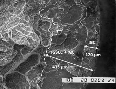
External ring of nonductile fracture observed after pre-exposure to 0.53 m NaCl for 264 h followed by straining in laboratory air. The outermost region (~120-μm depth) is due to IGC generated during pre-exposure. The remainder (~315 μm) is IGSCC produced during the slow strain rate testing at 2×10⁻⁶/s.
In addition to direct examination of the cracked surfaces, the crack depth at the point of catastrophic fracture can be estimated using the peak stress. Two methods available for this are shown in Appendix 1. In the first, it is assumed that the load-bearing capacity of the specimen is reduced by the peripheral crack, so the peak load after pre-exposure is compared with the peak load with no pre-exposure (Augustin, Andrieu, Baret-Blanc, Delfosse, & Odemer, 2010; Augustin, Andrieu, Baret-Blanc, Mankowski, & Delfosse, 2007; Larignon, Alexis, Andrieu, Odemer, & Blanc, 2014) to give an estimate of the peripheral crack depth. The second method is based on the idea that catastrophic fracture occurs when the stress intensity factor of the peripheral crack exceeds the fracture toughness of the material (Stark & Ibrahim, 1986, 1987). An experimentally measured short-transverse fracture toughness of K1c=18 MNm-3/2 was used in the calculation. Crack depths calculated by the two methods were in good agreement and are in agreement with depths of intergranular cracking measured on the fracture surfaces (Figure 5).
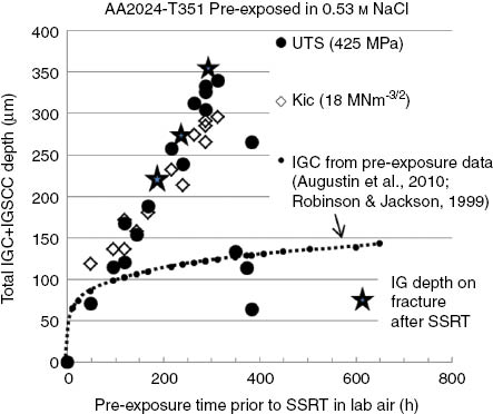
Depth of IGC plus IGSCC for specimens strained in laboratory air at a nominal strain rate of 10-5/s after pre-exposure to 0.53 m NaCl for various times. Published IGC depth as a function exposure time shown for comparison.
As shown in Figure 1, the tests carried out in dry air after pre-exposure followed a similar trend to the laboratory air tests, but the effect of pre-exposure time was less pronounced and longer times were needed before any cracking was detected (about 120 h compared to the 40 h for the laboratory air tests). In addition, much more scatter is evident in the dry air tests. Results of the tests in 0.53 m NaCl are shown in Figure 6, where peak stress is shown as a function of pre-exposure time for the specimens tested in 0.53 m NaCl under total immersion conditions. A slight downward trend in peak stress is evident, but this is due to the small loss of section arising from the IGC, predictable using metallographic measurements of IGC depth as a function of time from previous work (Augustin et al., 2010; Robinson & Jackson, 1999).
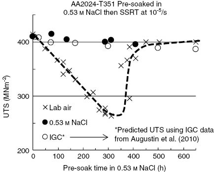
Graph showing the ineffectiveness of uninterrupted immersion on SCC. The peak stress for tensile specimens pre-exposed to 0.53 m NaCl under total immersion condition for various times and then subject to slow strain rate tensile tests in 0.53 m NaCl using a nominal strain rate of 10-5/s. The results for the specimens strained in laboratory air tests are shown as a dotted line for comparison.
3.2 Effect of strain rate
It is well known that the rate at which specimens are strained can have a large influence on the extent of environmentally controlled cracking. For this reason, the influence of strain rate on the magnitude of the pre-exposure effect was investigated to check that the results in Figure 6 are not, in some way, produced by a rate effect. Specimens were pre-exposed for 288 h and then strained using nominal strain rates between 10-7 and 10-4 s-1 (Figure 7).
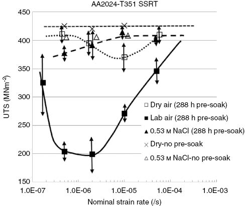
Effect of nominal strain rate on the peak stress for specimens pre-exposed to NaCl solution for 288 h and then strained to failure in various environments.
Considering the tests done in laboratory air first, it can be seen that the loss of mechanical strength was observed only at strain rates below ~10-4/s. The reduction in strength was greatest for strain rates ~10-6/s. Much less reduction in strength was observed at the lowest strain rate.
In dry air, the strength reduction was inconsistent and always significantly less than in laboratory air. The maximum effect was observed at a nominal strain rate ~10-5/s (Figure 7).
No significant embrittlement was found for specimens strained in 0.53 m NaCl, irrespective of the pre-exposure time or the nominal strain rate. The only detrimental effect of testing in 0.53 m NaCl was a minor UTS reduction associated with the IGC generated during pre-exposure.
3.3 Effect of electrochemical potential
The effect of controlling the electrochemical potential of AA2024-T351 during slow strain rate testing while fully immersed in 0.53 m NaCl is shown in Figure 8. Irrespective of the nominal strain rate employed, IGSCC only initiated and grew when the electrochemical potential was above the critical minimum of about -650 mV (SCE).
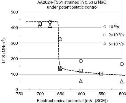
Peak stress (UTS) achieved in tests performed under electrochemical potential control. Note the range of strain rates used.
3.4 Fractrography
Figure 9 shows both intergranular fracture faces of a typical region of IGSCC. The grain boundary precipitates on one fracture face fit with holes or indents on the matching fracture face, suggesting the fracture followed the precipitate/alloy matrix interface. A similar observation has been reported for fracture surfaces formed by IGSCC in 7000 series Al-Zn-Mg-Cu alloys (Scamans, 1980). The fracture from pre-exposure to 0.53 m NaCl closely resembles that reported by many other researchers for the SCC of 2000 series alloys in saline environments (Braun, 1993; Izumoto & Nishimura, 2011; Lee et al., 2012; Maitra, 1981). No evidence of transgranular cracking was detected for AA2024-T351, unlike the case for Al-Zn-Mg-Cu alloys, where it can occur (i) at strain rates slightly above those supporting IG cracking (Holroyd & Hardie, 1981), (ii) for modestly over-aged tempers exposed to saline environments containing additional anions (Braun, 1997, 2009), and (iii) when loading is in a non-short-transverse orientation (Holroyd, 1990).
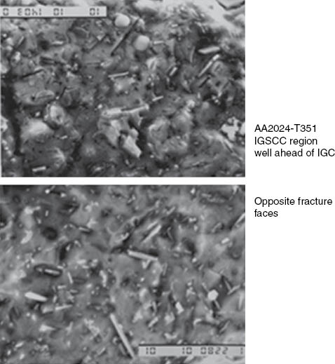
Face matching fracture surfaces for IGSCC well ahead of the region of IGC in a AA2024-T351 tensile specimen pre-exposed to 0.53 m NaCl prior to being strained to failure in laboratory air at nominal strain rate of 10-5/s.
3.5 Film removal
It was found that removal of the surface films and underlying corroded layers by mechanical polishing prior to strain rate testing eliminated all pre-exposure embrittlement, irrespective of the pre-exposure time or nominal strain rate. This showed that IGC corrosion is essential in order to initiate IGSCC.
4 Discussion
Two significant questions arise from the results presented above.
Why is the pre-exposure effect so immediately apparent when strain to failure is conducted in laboratory air, absent when testing is conducted in 0.53 m NaCl?
Why does the pre-exposure effect generated in laboratory air increase with pre-exposure times up to ~300 h, suddenly decrease with further pre-exposure, and become insignificant within 500 h of pre-exposure?
Why AA2024 does not crack under conditions of total immersion after pre-exposure is explained by the fact that the free corrosion potential (FCP) observed during strain rate testing rarely, if ever, exceeds the critical minimum potential of ~-660 mV (SCE) required for cracking to occur (see Figures 8 and 10). Further supporting evidence for the significance of electrode potential is provided by the work of Colner and Francis (1958) on smooth tensile test specimens of a similar alloy when strained in 1 m NaCl. Here, as with AA2024-T351, IGSCC initiation under total immersion conditions required anodic stimulation. In this instance, a sufficient hydrogen peroxide addition to the 1 m NaCl promoted cracking. SCC failure time data taken from their work, along with the typical free corrosion potentials generated by their peroxide additions are shown in Figure 11.
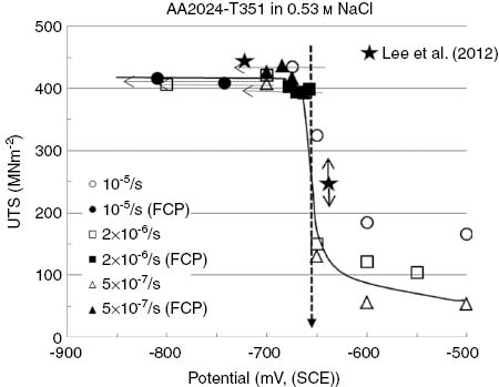
AA2024-T351 FCP during slow strain rate testing in 0.53 m NaCl, superimposed on the peak stress data obtained at FCP and under potentiostatic control (see Figure 8) (FCP’s move in a negative direction during SSRT testing, as indicated by the arrows).
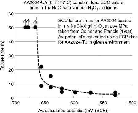
Failure times for under-aged AA2024 (6 h 177°C) subjected to constant load SCC testing under total immersion conditions in 1 m NaCl with various additions of hydrogen peroxide (0–3.5 g/l) taken from Colner and Francis (1958) with average electrochemical potentials during testing using data for AA2024-T3 immersed in similar test solutions.
In our tests, the samples were cathodically protected, despite the IGC introduced during pre-exposure to 0.53 m NaCl.
It is well established that AA2024-T351 plate material exposed to 0.53 m NaCl under total immersion conditions will suffer IGC. Augustin et al. (2007, 2010) have recently provided metallographic evidence of the IGC developed in the short transverse plane for 50-mm-thick AA2024-T351 plate exposed to a range of sodium chloride concentrations (0.5–5 m). On the basis of their published data, the maximum IGC depth expected during the pre-exposure of AA2024-T351 tensile specimens used in this study will be below 200 μm, and for pre-exposure times of ~300 h will typically be around 100–120 μm, as observed in the present work (Figure 4).
A local environment will be retained within the IGC sites generated during pre-exposure, and IGSCC will initiate from these sites if a sufficient mechanical driving force is applied in laboratory air prior “drying out” leading to a loss of the local environment.
Support for this assertion is provided by the following: (a) similar IGSCC growth rates generated during the slow strain rate testing of the pre-exposed AA2024-T351 tensile samples used in this study (Table 1) and those reported by Blain et al. (1984) for AA2024-T351 pre-cracked test specimens tested under total immersion conditions in 0.53 m NaCl (Figure 12), (b) IGSCC is prevented when (i) surface-filmed layers generated during pre-exposure are removed by light mechanical polishing just prior to slow strain rate testing, (ii) pre-exposed test specimens are left unloaded in laboratory air for a sufficient period prior to strain rate testing (Figure 3), and (iii) strain testing is conducted under total immersion conditions (Figure 6).
Estimated IGSCC depth (using the first method shown in the Appendix, assuming UTS=435 MPa) and calculated crack growth rates for AA2024-T351 subjected to slow strain rate testing at various nominal strain rates in laboratory air, after previously being pre-exposed to 0.53 m NaCl under total immersion conditions for 288 h under no external loading (IGSCC assumed to occur during plastic straining).
| Nominal strain rate (/s) | Maximum load (kN) | Calculated IGSCC+IGC (μm) | IGSCC growth (μm) | Plastic straining time (s) | IGSCC growth rate (m/s) |
|---|---|---|---|---|---|
| 5×10⁻⁵ | 2.59 | 199 | 79 | 4378 | 4.6×10⁻⁸ |
| 10-5 | 2.14 | 326 | 206 | 8690 | 3.8×10⁻⁸ |
| 2.22 | 304 | 184 | 5830 | 5.2×10⁻⁸ | |
| 2.12 | 333 | 213 | 7260 | 4.6×10⁻⁸ | |
| 2×10⁻⁶ | 1.88 | 406 | 286 | 8250 | 4.9×10⁻⁸ |
| 1.30 | 607 | 487 | 8800 | 6.9×10⁻⁸ |
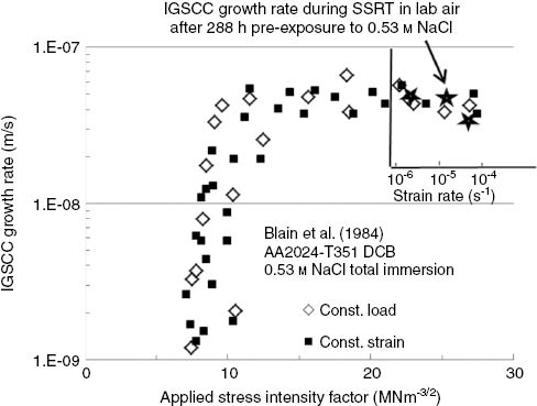
Comparison of IGSCC growth rates generated during the slow strain rate testing of pre-exposed AA2024-T351 tensile samples with published IGSCC growth rate data for AA2024-T351 plate exposed to 0.53 m NaCl (Blain et al., 1984).
On the basis of our findings, an IGC depth of at least 80–100 μm and the availability of a suitable local environment are required for IGSCC to initiate during slow strain rate testing in laboratory air (Figure 13). It is not immediately obvious, however, why the depth of IGSCC generated during straining linearly increases with pre-exposure times up to around 300 h, suddenly decreases with further pre-exposure, reducing to a negligible effect within a further 200 h of pre-exposure (Figure 5) whereas the depth of the IGC promoted during pre-exposure continually increases logarithmically with time.
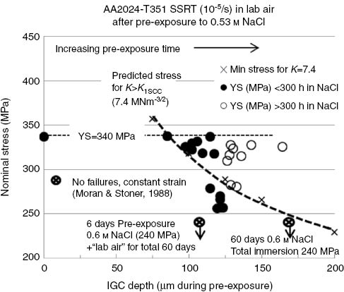
Off-set stress measured during slow strain rate testing of AA2024-T351 in laboratory air (10-5/s) as a function of the depth of IGC generated during pre-exposure to 0.53 m NaCl for various times.
So far, we have concentrated on the peak stress in considering the experimental results. This stress represents the point where fracture becomes catastrophic after IGSCC has produced a crack of a critical size. However, some nonlinearity in the force-displacement record was observed before this point was reached, representing subcritical crack growth and possibly some concomitant plasticity. The onset of this process was characterized by taking the equivalent of a 0.2% off-set stress. The measured off-set stresses are correlated with the depths of the IGC cracks in Figure 13. The data here are principally for pre-exposed specimens of the present material subsequently strained in laboratory air.
We now make the supposition that subcritical crack growth can be nucleated from the IGC defects only when the stress intensity factor associated with the defect is larger than the critical stress intensity factor K1SCC for IGSCC. K1SCC is known to be ~7.4 MNm-3/2, measured using conventional fracture toughness specimens, see data in Figure 12 (Blain et al., 1984) or that required for IGSCC to promote the fracture of smooth tensile specimens when loaded to ~50 MPa, the well documented SCC threshold stress for AA2024-T351 subjected to alternate immersion SCC testing (Sprowls, Brown, & Shumaker, 1972). This supposition is included in Figure 13 as a plot of the minimum stress required to achieve the critical condition at any given IGC crack length.
The two “non-failure” data points shown in Figure 13 are results provided by Moran and Stoner (1988) for under-aged AA2024 (3 h at 190°C) short transverse tensile specimens (similar design as used in this work) loaded to a stress of 240 MPa and then immediately pre-exposed to 0.6 m NaCl for 6 days, followed by being either (a) left under load in the saline solution for at least 60 days or (b) removed from the 0.6 m NaCl and exposed to laboratory air (50% RH) for at least 60 days while remaining under load. These two “non-failure” conditions are consistent with our findings in that the results under total immersion conditions confirm IGSCC initiation in smooth test specimens is difficult without some form of stimulation, and the lack of any IGSCC-induced failures for pre-loaded pre-exposed tensile samples with 6 days pre-exposure to 0.6 m NaCl upon exposure to laboratory air (50% RH) is expected when it is realized the maximum local stress intensity factors generated by the ~100-μm-deep IGC sites promoted during pre-exposure will be ~5.7 MNm-3/2, i.e. below the threshold stress intensity factor needed for IGSCC initiation, K1SCC ~7.4 MNm-3/2.
Moran and Stoner’s (1988) “non-failure result”, which we have attributed to IGSCC initiation conditions not being satisfied, also provides an explanation why the depth of IGSCC promoted in AA2024-T351 after pre-exposure to 0.53 m NaCl, can increase significantly with pre-exposure times up to ~300 h, suddenly starts decreasing with pre-exposure times >~300 h, eventually becoming negligible after around 500 h pre-exposure (Figure 6). A basic assumption in all of the above is that exposure of specimens to NaCl solution produces IGC defects that are crack-like in form and that there is no barrier to them being able to nucleate subsequent IGSCC. Metallographic evidence does support the crack-like nature of the IGC fissures when pre-exposure times are not too long, but for extended exposure (>300 h), the cracks widen and become more like multiple fissures than cracks. Evidence of this is provided by the IGC morphologies in AA2024-T351 generated by pre-exposure to 0.5 m NaCl for 24, 72, 168, and 3000 h, as presented in the paper of Augustin et al. (2010) in Figures 5 and 9. Additional support for the blunting hypothesis is provided by our experimental observation of the expected ~150-μm-deep, broad, and blunt fissures in failed tensile samples having had long-term pre-exposures to 0.53 m NaCl.
Further work is needed to fully quantify what exposure times to laboratory air are needed to “dry out” the local environments contained within the IGC sites generated during pre-exposure to 0.53 m NaCl. It is reasonable to assume given sufficient time that this phenomenon will become important. For example, the reduced loss of mechanical properties promoted during testing at the lowest nominal strain rates (1.5×10⁻⁷/s) (Figure 7) is attributable to a “drying out” effect, as, at least partially, is the reduced loss of mechanical properties promoted when long hold times in laboratory air are introduced prior to the slow strain rate testing of pre-exposed specimens in laboratory air (Figure 3). It is unlikely, however, the “drying out” effects will be of any significance for pre-exposed AA2024-T3 tensile samples tested at nominal strain rate above around 10-6/s, where strain-to-failure will be completed within a few hours, well below the 16 h or more needed in laboratory air for the “drying out” of local environments contained within restricted geometries promoting accelerated IGSCC in pre-exposed pre-cracked AA7150-T651 test specimens (Newton & Holroyd, 1992).
The concept of “non-propagating” cracks is not new (El Haddad, Topper, & Smith, 1979; Parkins, 1979, 1988), and a revived interest in their role in SCC (Castro & Leite, 2013; Castro, Landim, Leite, & Meggiolargo, 2014) has led the authors to consider this further in a future publication.
5 Conclusions
When samples of the alloy are immersed in NaCl solution, short, intergranular fissures are developed. The depth and morphology of the IGC defect growth are highly nonlinear, with initial high penetration rates, which decreases rapidly with time. Initially, the defects are narrow and crack-like, but then broaden and then evolve into multiple blunt fissures.
AA2024-T351 tensile samples are resistant to stress corrosion crack initiation in 0.53 m NaCl at the free corrosion potential under total immersion conditions, irrespective of the pre-exposure time in 0.53 m NaCl or the nominal strain rate applied because the alloys electrochemical potential under total immersion conditions is always below the minimum potential (~-660 mV SCE) required for IGSCC initiation.
Initiation of IGSCC specimens strained in laboratory air (relative humidity 58–60%) is highly dependent upon the morphology of the IGC and the local environment retained within the IGC sites generated during pre-exposure to 0.53 m NaCl. Mechanical property loss during slow strain rate testing in the laboratory can be significantly reduced when sufficient time prior to and/or during testing permits these local environments to dry out.
Subcritical (IGSCC) propagation in tensile samples strained in laboratory air after being pre-exposed to 0.53 m NaCl between 48 and 300 h resulted in peripheral rings of cracking with depths that could be estimated using the peak load.
Specimens that had been pre-exposed for >300 h showed much less cracking on straining in laboratory air. Specimens that had been pre-exposed for 500 h showed no IGSCC due to the morphology of the intergranular attack providing blunt, multiple fissures as opposed to the crack-like features generated by shorter pre-exposure times.
Subcritical crack growth (IGSCC) initiation can be prevented by removal of the corroded surface layers generated during pre-exposure. IGSCC requires ~80 μm of IGC, the minimum depth needed at the alloy’s yield stress for the associated stress intensity factor to exceed the published IGSCC threshold.
About the authors
N.J. Henry Holroyd is a self-employed consultant retained by several clients and an Adjunct Professor with Case Western Reserve University, Cleveland, Ohio, having previously been Senior Vice President of Luxfer Gas Cylinders with global responsibility for Technology and Innovation and a visiting Professor at several UK Universities. Has published well over 100 scientific papers, mainly on the localized corrosion and environment-assisted-cracking of higher-strength aluminium alloys, and is the first named inventor on 7 granted globally patents associated with aluminium alloy usage in metal-spray coatings, welding technology and pressure vessel technology. Hobbies include: playing tenor saxophone (mainstream jazz), golf and collecting/appreciating fine wine.
J.T. Evans is Emeritus Professor at the University of Newcastle upon Tyne and was previously head of the Department of Mechanical, Materials and Manufacturing Engineering. He has extensive publications in the following areas: Dislocations and Plastic Flow in Metals and Alloys; Fracture and Sub-critical Crack Growth in Metals and Composites; Residual Stresses, Fatigue and Surface Contact Fatigue in Gearing; Design and Performance of Carbon-Fibre Composites and Fire-resistance of Carbon-fibre Composites. Included in his most recent publication is work on Magnetism and Barkhausen Emission in Ferromagnetic Materials.
Geoffrey M. Scamans is the Chief Scientific Officer at Innoval Technology and is a Professor of Metallurgy at Brunel University. His expertise is in light metals and their applications in the automotive and aerospace industries, and in knowledge transfer from the research base to industry. Over the last 40 years he has initiated and managed a number of R&D programmes on both materials development and technological innovation, making scientific and technological contributions to the light metals sector, described in over 150 publications. His main interests are in the closed loop recycling of aluminium alloys as an alternative to primary production in order to transform the aluminium industry from packaging based products into transport based products (“Cans to Car”). His other main interest is in understanding the development and properties of deformed surface layers on aluminium alloys and their control through efficient cleaning and pretreatment processes to increase line speeds in sheet finishing operations and to eliminate cosmetic corrosion.
Appendix 1: Estimating crack depth
As stated in the text, the crack depth at the point of final fast fracture was estimated using two methods, assuming in both cases that a uniform peripheral crack depth a had formed in the tensile specimen during SCC. The two methods gave comparable results, but for completeness both are reported below.
In the first method, the tensile strength σ0 is used to calculate the crack depth. It is assumed that fast fracture occurs when the net section stress achieves the value of the tensile strength (Augustin et al., 2007, 2010; Larignon et al., 2014). The crack depth is then given by
(A1)where D is the specimen diameter, and P is the load at fracture.
In the second method, the critical stress intensity factor K1c is used to calculate the crack depth. It is assumed that fast fracture occurs when the stress intensity factor of the peripheral crack reaches a critical value. An initial estimate a1 of the crack depth is then obtained by interpolation using the relation (Stark & Ibrahim, 1986, 1987)
(A2)where F(a)=1.25[1-(2a/D)1.47]-2.4.
Finally, the crack depth is obtained by applying a plasticity correction, a=a1-ry, where ry=1/(6π)(KIc/σ0)2.
References
Abodi LC, DeRose JA, Van Damme S, Demeter A, Suter T, Deconinck J. Modeling localized aluminum alloy corrosion in chloride solutions under non-equilibrium conditions: steps toward understanding pitting initiation. Electrochim Acta 2012; 63: 169–178.10.1016/j.electacta.2011.12.074Suche in Google Scholar
Augustin C, Andrieu E, Baret-Blanc C, Mankowski G, Delfosse J. Intergranular corrosion in 2024 alloy in chloride solutions. J Electrochem Soc 2007; 154: C637–C644.10.1149/1.2778224Suche in Google Scholar
Augustin C, Andrieu E, Baret-Blanc C, Delfosse J, Odemer G. Empirical propagation of intergranular corrosion defects affecting 2024-T351 in chloride solutions. J Electrochem Soc 2010; 157: C428–C436.10.1149/1.3497297Suche in Google Scholar
Blain J, Masounave J, Dickinson JI. A comparison of SCC velocity measurements under constant load and constant displacement. Corros Sci 1984; 24: 1–12.10.1016/0010-938X(84)90131-8Suche in Google Scholar
Boag A, Hughes AE, Glenn AM, Muster TH, McCulloch D. Corrosion of AA2024-T3 Part I: localised corrosion of isolated IM particles. Corros Sci 2011; 53: 17–26.10.1016/j.corsci.2010.09.009Suche in Google Scholar
Branco CM, Radon JC, Culver LE. Influence of specimen orientation and loading history on SCC in aluminium alloy. Corros Sci 1977; 17: 125–141.10.1016/0010-938X(77)90013-0Suche in Google Scholar
Braun R. Investigation of SCC behavior of alloy 2024 using slow strain rate technique. Werkst Korros 1993; 44: 73–82.10.1002/maco.19930440304Suche in Google Scholar
Braun R. Slow strain rate testing of alloy 7050 in different tempers using various environments. Corrosion 1997; 53: 467–474.10.5006/1.3280489Suche in Google Scholar
Braun R. Stress corrosion cracking behaviour of alloy 7050-T7451 plate in aqueous chloride-nitrate solution. In: Somerday B, Sofronis P, Jones R, editors. Effects of hydrogen on materials, Proceedings of the 2008 International Hydrogen Conference, ASM International, 2009: 251–258.Suche in Google Scholar
Castro JTP, Leite JCC. Does notch sensibility exist in environmentally assisted cracking? J Mater Res Technol 2013; 2: 288–295.10.1016/j.jmrt.2013.02.010Suche in Google Scholar
Castro JTP, Landim RV, Leite JCC, Meggiolargo MA. Prediction of notch sensitivity effects in fatigue and environmentally assisted cracking. Fatigue Fract Eng Mater Struct 2014; 00: 1–19.Suche in Google Scholar
Colner WH, Francis HT. A contribution to the theory of stress corrosion in Al-4%Cu alloys. J Electrochem Soc 1958; 105: 377–384.10.1149/1.2428867Suche in Google Scholar
DeRose JA, Suter T, Bałkowiec A, Michalski J, Kurzydlowski KJ, Schmutz P. Localised corrosion initiation and microstructural characterisation of an Al 2024 alloy with a higher Cu to Mg ratio. Corros Sci 2012; 55: 313–325.10.1016/j.corsci.2011.10.035Suche in Google Scholar
Dietzel W, Schwalbe KH, Wu D. Application of fracture mechanics techniques to the environmentally assisted cracking of aluminum 2024. Fatigue Fract Eng Mater Struct 1989; 12: 495–510.10.1111/j.1460-2695.1989.tb00559.xSuche in Google Scholar
Dix EH. Acceleration of the rate of corrosion by high constant stress. AIME Trans 1940; 137: 11–40.Suche in Google Scholar
El Haddad MH, Topper TH, Smith KN. Prediction of non propagating cracks. Eng Fract Mech 1979; 11: 573–584.10.1016/0013-7944(79)90081-XSuche in Google Scholar
Farmery HK, Evans UR. The stress corrosion of certain aluminum alloys. J Inst Met 1955–56; 84: 413–422.Suche in Google Scholar
Garner A, Tromans D. Direct observation of intergranular corrosion in Al-4 wt% Cu alloy. Corrosion 1979; 35: 55–60.10.5006/0010-9312-35.2.55Suche in Google Scholar
Glenn AM, Muster TH, Luo C, Zhou X, Thompson GE, Boag A, Hughes AE. Corrosion of AA2024-T3 Part III: propagation. Corros Sci 2011; 53: 40–50.10.1016/j.corsci.2010.09.035Suche in Google Scholar
Hardwick DA, Taheri M, Thompson AW, Bernstein IM. Hydrogen embrittlement in a 2000-series aluminum alloy. Met Trans 1982; 13A: 235–239.10.1007/BF02643313Suche in Google Scholar
Holroyd NJH. Environment-induced cracking of high-strength aluminum alloys. In: Gangloff RP, Ives MB, editors. Environment-induced cracking of metals. Houston: NACE-10, 1990: 311–345.Suche in Google Scholar
Holroyd NJH, Hardie D. Strain-rate effects in the environmentally assisted fracture of a commercial high-strength aluminum alloy (7049). Corros Sci 1981; 21: 129–144.10.1016/0010-938X(81)90097-4Suche in Google Scholar
Holroyd NJH, Scamans GM. Slow-strain-rate stress corrosion cracking of aluminum alloys. In: Dean SW, Pugh EN, Ugiansky GM, editors. Environment-sensitive fracture: evaluation and comparison of test methods. Philadelphia: ASTM STP 821, 1984: 202–241.10.1520/STP34434SSuche in Google Scholar
Hughes AE, Boag A, Glenn AM, McCulloch D, Muster TH, Ryan Luo C, Zhou X, Thompson GE. Corrosion of AA2024-T3 part II: co-operative corrosion. Corros Sci 2011; 53: 27–39.10.1016/j.corsci.2010.09.030Suche in Google Scholar
Hughes AE, Parvizi R, Forsyth M. Microstructure and corrosion of AA2024. Corrosion Rev 2015; 33: 1–30.10.1515/corrrev-2014-0039Suche in Google Scholar
Hyatt MV. Use of precracked specimens in stress corrosion testing of high strength aluminum alloys. Corrosion 1970; 26: 487–503.10.5006/0010-9312-26.11.487Suche in Google Scholar
Izumoto E, Nishimura R. Environment-induced cracking of Al-Cu alloy (AA2017P-T3) under constant load in distilled water and sodium chloride solutions. Corros Sci 2011; 53: 886–893.10.1016/j.corsci.2010.11.012Suche in Google Scholar
Ketchem SJ. Polarization and stress corrosion studies on an Al-Cu-Mg alloy. Corros Sci 1967; 7: 305–314.10.1016/S0010-938X(67)80020-9Suche in Google Scholar
King PC, Cole IS, Corrigan PA, Hughes AE, Muster TH. FIB/SEM study of AA2024 corrosion under a seawater drop: part I. Corros Sci 2011; 53: 1086–1096.10.1016/j.corsci.2010.12.004Suche in Google Scholar
Knight SP, Salagaras M, Trueman AR. The study of intergranular corrosion in aircraft aluminium alloys using X-ray tomography. Corros Sci 2011; 53: 727–734.10.1016/j.corsci.2010.11.005Suche in Google Scholar
Larignon C, Alexis J, Andrieu E, Odemer G, Blanc B. Propagation of intergranular corrosion defects in AA 2024-T351 evaluated by a decrease in mechanical resistance. J Electrochem Soc 2014; 161: C339–C348.10.1149/2.090406jesSuche in Google Scholar
Lee H, Kim Y, Jeong Y, Kim S. Effects of testing variables on stress corrosion cracking susceptibility of Al 2024-T351. Corros Sci 2012; 55: 10–19.10.1016/j.corsci.2011.09.021Suche in Google Scholar
Little DA, Connolly BJ, Scully JR. An electrochemical framework to explain the intergranular stress corrosion behavior in two Al-Cu-Mg-Ag alloys as a function of aging. Corros Sci 2007; 49: 347–372.10.1016/j.corsci.2006.04.024Suche in Google Scholar
Liu X, Frankel GS, Zoofan B, Rokhlin SI. Transition from intergranular corrosion to intergranular stress corrosion cracking in AA2024-T3. J Electrochem Soc 2006; 153: B42–B51.10.1149/1.2142288Suche in Google Scholar
Liu X, Frankel GS, Zoofan B, Rokhlin SI. In-situ observation of intergranular stress corrosion cracking in AA2024-T3 under constant load conditions. Corros Sci 2007; 49: 139–148.10.1016/j.corsci.2006.05.013Suche in Google Scholar
Logan HL, Hessing H. Stress corrosion tests on high-strength aluminum alloy sheet. J Res Nat Bur Stand 1948; 46: 69–86.10.6028/jres.041.010Suche in Google Scholar
Luo C, Zhou X, Thompson GE, Hughes AE. Observations of intergranular corrosion in AA2024-T351: the influence of grain stored energy. Corros Sci 2012; 61: 35–44.10.1016/j.corsci.2012.04.005Suche in Google Scholar
Maitra S. Determination of stress corrosion cracking resistance of Al-Cu-Mg alloys by slow strain rate and alternate immersion testing. Corrosion 1981; 37: 98–103.10.5006/1.3593853Suche in Google Scholar
Malladi SRK, Xu Q, Tichelaar FD, Zandbergen HW, Hannour F, Mol JMC, Terryn H. Early stages during localized corrosion of AA2024 TEM specimens in chloride environment. Surf Interface Anal 2013; 45: 1619–1625.10.1002/sia.5193Suche in Google Scholar
Mears RB, Brown RH, Dix EH. A generalized theory for the stress corrosion of alloys. In: Symposium on stress-corrosion cracking of metals. ASTM and AIME: 1945: 323–344.10.1520/STP42581SSuche in Google Scholar
Moran JP, Stoner GE. Solution chemistry effects on the stress corrosion cracking behavior of alloy 2090 (Al-Li-Cu) and alloy 2024 (Al-Cu-Mg). In: Sanders TH, Starke EA, editors. Aluminum-Lithium V. Birmingham, UK: MCE Publications, Ltd, 1988: 1187–1196.Suche in Google Scholar
Mulherin JH. Influence of environment on crack propagation characteristics of high strength aluminum alloys. In: Stress corrosion testing. Philadelphia: ASTM-STP 425, 1967: 66–81.10.1520/STP46453SSuche in Google Scholar
Newton CJ, Holroyd NJH. Time-lapse video techniques in the corrosion testing of aluminum alloys. In: Agarwala VS, Ugianski GM, editors. New methods for corrosion testing in the corrosion of aluminum alloys. Philadelphia: ASTM STP 1134, 1992: 153–179.10.1520/STP19588SSuche in Google Scholar
Parkins RN. Development of strain-rate testing and its implications. In: Ugiansky GM, Payer JH, editors. Stress corrosion cracking – the slow strain-rate technique. Philadelphia: ASTM STP 665, 1979: 5–25.10.1520/STP38106SSuche in Google Scholar
Parkins RN. Localized corrosion and initiation. Mater Sci Eng 1988; 103A: 143–156.10.1016/0025-5416(88)90562-9Suche in Google Scholar
Rawdon HS, Krynitsky AI, Berliner JFT. Brittleness developed in aluminum and duralumin by stress and corrosion. Chem Metall Eng 1922; 26: 154–158.Suche in Google Scholar
Reboul MC, Magnin T, Warner TJ. Stress corrosion cracking of high strength aluminium alloys. In: The Third International Conference on Aluminium Alloys, Conference proceedings, Vol. 2, Trondheim, Norway, 1992: 453–460.Suche in Google Scholar
Robinson MJ, Jackson NC. Exfoliation corrosion of high strength Al-Cu-Mg alloys: effect of grain structure. Br Corros J 1999; 34: 45–49.10.1179/bcj.1999.34.1.45Suche in Google Scholar
Scamans GM. Evidence of crack-arrest markings on intergranular stress corrosion fracture surfaces in Al-Zn-Mg alloys. Met Trans 1980; 11A: 846–850.10.1007/BF02661215Suche in Google Scholar
Sprowls DO. Written discussion. In: Stress corrosion testing. Philadelphia: ASTM-STP 425, 1967: 81–83.Suche in Google Scholar
Sprowls DO, Brown RH. Stress corrosion mechanisms for aluminum alloys. In: Staehle RW, Forty AJ, Van Rooyen D, editors. Fundamental aspects of stress corrosion cracking. Houston: NACE, 1969: 466–512.Suche in Google Scholar
Sprowls DO, Brown RH, Shumaker MB. The resistance of high strength aluminum alloys to stress corrosion cracking. In: Stress corrosion cracking in metals – a sate of the art. Philadelphia: ASTM STP 518, 1972: 87–118.10.1520/STP34697SSuche in Google Scholar
Stark HL, Ibrahim RN. Estimating fracture toughness from specimens. Eng Fract Mech 1986; 25: 395–401.10.1016/0013-7944(86)90253-5Suche in Google Scholar
Stark HL, Ibrahim RN. Validity requirements for fracture toughness measurements obtained from small circumferentially notched cylindrical specimens. Eng Fract Mech 1987; 28: 455–460.10.1016/0013-7944(87)90190-1Suche in Google Scholar
Sugimoto K, Hoshino K, Kageyama M, Kageyama S, Sawada Y. Stress corrosion cracking of aged Al-4%Cu alloy in NaCl solution. Corros Sci 1975; 15: 709–720.10.1016/0010-938X(75)90035-9Suche in Google Scholar
Ugiansky GM, Johnson CE, Thompson DS, Gillespie EH. Slow strain-rate testing of aluminum alloys. In: Ugiansky GM, Payer JH, editors. Stress corrosion cracking – the slow strain-rate technique. Philadelphia: ASTM STP 665, 1979: 254–265.10.1520/STP38119SSuche in Google Scholar
Urshino K, Sugimoto K. Stress corrosion cracking of aged Al-Cu-Mg alloys in NaCl solution. Corros Sci 1979; 19: 225–236.10.1016/0010-938X(79)90008-8Suche in Google Scholar
Xiao J, Chauduri S. Predictive modeling of localized corrosion: an application to aluminum alloys. Electochim Acta 2011; 56: 5630–5641.10.1016/j.electacta.2011.04.019Suche in Google Scholar
Zang W, Frankel GS. Transitions between pitting and intergranular corrosion in AA2024. Electrochim Acta 2003; 48: 1193–1210.10.1016/S0013-4686(02)00828-9Suche in Google Scholar
Zhou X, Luo C, Hashimoto T, Hughes AE, Thompson GE. Study of localized corrosion in AA2024 aluminium alloy using electron tomography. Corros Sci 2012; 58: 299–306.10.1016/j.corsci.2012.02.001Suche in Google Scholar
Zhou X, Luo C, Ma Y, Hashimoto T, Thompson GE, Hughes AE, Skeldon P. Grain-stored energy and the propagation of intergranular corrosion in AA2xxx aluminium alloys. Surf Interface Anal 2013; 45: 1543–1547.10.1002/sia.5218Suche in Google Scholar
©2015 by De Gruyter
Artikel in diesem Heft
- Frontmatter
- In this issue
- Editorial
- International Symposium on Environmental Damage Under Static and Cyclic Loads in Structural Metallic Materials at Ambient Temperatures III (Bergamo, Italy, June 15–20, 2014)
- Overviews and reviews
- U.S. Naval Aviation: operational airframe experience with combined environmental and mechanical loading
- Thirty-five years in environmentally assisted cracking in Italy: a point of view
- Fatigue and corrosion fatigue
- Transgranular corrosion fatigue crack growth in age-hardened Al-Zn-Mg (-Cu) alloys
- Effect of cyclic frequency on fracture mode transitions during corrosion fatigue cracking of an Al-Zn-Mg-Cu alloy
- Crack growth behavior of 4340 steel under corrosion and corrosion fatigue conditions
- Modeling of environmentally assisted fatigue crack growth behavior
- Factors influencing embrittlement and environmental fracture
- Pre-exposure embrittlement of an Al-Cu-Mg alloy, AA2024-T351
- Electrochemical approach to repassivation kinetics of Al alloys: gaining insight into environmentally assisted cracking
- Localized dissolution of grain boundary T1 precipitates in Al-3Cu-2Li
- Grain boundary anodic phases affecting environmental damage
- Defect tolerance under environmentally assisted cracking conditions
- Role of Mo/V carbides in hydrogen embrittlement of tempered martensitic steel
- Stress corrosion cracking
- The role of crack branching in stress corrosion cracking of aluminium alloys
- An atomistically informed energy-based theory of environmentally assisted failure
- Discrete dislocation modeling of stress corrosion cracking in an iron
- Quasi-static behavior of notched Ti-6Al-4V specimens in water-methanol solution
- Role of excessive vacancies in transgranular stress corrosion cracking of pure copper
- Multiscale investigation of stress-corrosion crack propagation mechanisms in oxide glasses
- Hydrogen assisted cracking
- Hydrogen effects on fracture of high-strength steels with different micro-alloying
- Environmentally assisted cracking and hydrogen diffusion in traditional and high-strength pipeline steels
- Multiscale thermodynamic analysis on hydrogen-induced intergranular cracking in an alloy steel with segregated solutes