One-step preparation and characterization of core-shell SiO2/Ag composite spheres by pulse plating
-
 ,
,

Abstract
A simple method of one-step pulse plating was used in the fabrication of core-shell SiO2/Ag composite spheres. Structural characteristics and morphologies of the prepared SiO2/Ag composite spheres are characterized by means of X-ray diffraction, scanning electron microscope, and transmission electron microscopy. The Ag shell is uniformly coated on the surface of SiO2 spheres with the thickness of about 20 nm. Photoluminescence (PL) spectrum has revealed that PL of the core-shell samples is much stronger than that of bare SiO2 spheres. Raman spectrometer measurements show that the SiO2/Ag composite spheres have excellent surface-enhanced Raman scattering performance. In addition, the current-voltage characteristic of SiO2/Ag composite spheres has improved at the same time.
1 Introduction
Nowadays, a great deal of research attention is devoted to the development of core-shell composite spheres, which consist of a dielectric solid sphere (e.g. silica, polystyrene) covered by a metallic nanoshell [1, 2]. Especially, an increasing number of research studies have been focused on the core-shell composite spheres with Ag nanoshells because of their great potential applications in catalysis [3], chemical and biological sensing [4], optoelectronics, photonic crystals, magnetics [5], plasmonics and surface-enhanced Raman scattering-based analytical devices [6, 7], and so on.
So far, several researchers have demonstrated a large number of chemical routes for the preparation of core-shell particles, e.g. the electroless deposition method [8], complex or ion pair formation prior to reduction [9], seeding plating process [10, 11], layer by layer method [12], and so on. In most of these methods, the pretreatment process is often used for functional or physical modification of the silica spheres’ surface, and then the Ag nanoshell is attached to the core surface so that the silver particles and the surface of silica can form effective bonds. Particularly, one of the chemical routes, termed the layer by layer method, has become a very attractive topic of investigation since the pioneering work done by Caruso et al. [13], the basic of which is the electrostatic association between alternately deposited, oppositely charged species.
As is commonly understood, it is quite difficult to form a complete and compact Ag nanoshell with the aforementioned approaches. Obviously, most of these chemical methods are complicated and unpurified. In practice, easy method and low cost are important factors in industrial applications. Therefore, it is very important to adopt a kind of simple and one-step method of the preparation of composite spheres.
Alluding to the mentioned shortcomings, in this work we take on a comparatively simple method for the fabrication of SiO2/Ag composite spheres with the aid of pulse plating. Pulse plating is usually used to obtain a dense and uniform coating by adjusting plating parameters [14]. In this work, we prepared SiO2/Ag core-shell composite spheres successfully via a pulse plating one-step method. As a matter of fact, this method is much easier than others currently reported.
2 Materials and methods
2.1 Materials
The silica particles used in this experiment were provided directly by a factory rather than the widely known modified Stöber et al. [15] synthesis and used for the preparation of homogeneous silica spheres. The electroplating baths used were silver nitrate (42~50 g/l), ammonium acetate (77 g/l), ammonia (32 ml/l), KOH (45~55 g/l), and niacin (90~110 g/l), K2CO3 (70~82 g/l) – all of which were analytical reagents (AR) purchased from Sinopharm Chemical Reagent Co. Ltd, Shanghai, China. Ultrapure water (about 0.21 MΩ·cm) from an “up water purification system” produced by ULUPURE (Sichuan, China) was used throughout the whole experiment. In addition, titanium plates were used as the cathodes and Ag plates as the anodes in the pulse plating.
2.2 Synthesis of SiO2/Ag core-shell spheres
The typical scheme is presented in Figure 1. The mechanism of composite spheres produced in cathodes is as follows.

Schematic illustration of deposition procedure for synthesizing the SiO2/Ag composite spheres.
In general, it is believed that particles will be in accelerated motion to the cathode under the force of the electric field because of the particles’ surface adsorption positive charge. In a uniform electric field between two electrodes, the deposition rate (V) of particles in the cathode is expressed as follows:
U is the potential difference between the electrodes, q is the quantity of the particles’ electric charge, and m is the quality of the particles.
The deposition rate is associated with both the adsorbed amount of the charge and the quantity of the particles. Therefore, in the initial plating, SiO2 particles move quickly to the cathode under the action of an electric field while SiO2 particles are coated with silver. In the one-step preparation of SiO2/Ag composite spheres, the silica particles should be mixed with ultrapure water via ultrasonic processing in order to make sure the blending suspension is even, and then the power supply should be turned on at a current density of 0.2–0.4 A/dm2 [16].
2.3 Thermal annealing
To obtain dense coating, the as-prepared samples should be roasted in a chemical vapor deposition (CVD) furnace (SK2-4-13A, China) under an Argon atmosphere.
3 Results and discussion
3.1 X-ray diffraction (XRD)
Crystal structure identification was accomplished using a powder X-ray diffractometer (Rigaku Ultima IV with D/tex Ultra, Japan) operating at 40 KV and 30 mA with Cu Kα radiation (with the corresponding X-ray wavelength of λ=1.54056 nm) at a scanning rate of 0.02 degrees per second in the 2θ ranging from 10 to 80 degrees.
The XRD patterns of bare silica powders shown in Figure 2a indicate that the bare silica is in an amorphous state. The strongest diffraction peak is still only the crystalless state of aggregation. The XRD patterns of SiO2/Ag composite spheres, as demonstrated in Figure 2b, exhibited diffraction peaks at 2θ angles of 38.1°, 44.3°, 64.4°, and 77.4°, corresponding to the reflections of (111), (200), (220), and (311) crystalline planes of the face centered cubic (fcc) structure of Ag (PCPDF # 893722) [17].

(a) XRD patterns of bare silica powder; (b) SiO2/Ag composite spheres prepared by pulse plating.
3.2 Scanning electron microscope (SEM) observation
The morphologies of as-prepared samples were analyzed with a field-emission SEM (JEOL JSM-7500F, Japan) operating at an accelerating voltage of 5 KV.
In Figure 3a and b, some small spheres have attached to big ones because of aggregation. But the surface of all spheres is obviously smooth. The as-prepared core-shell SiO2/Ag composite spheres are shown in Figure 3c and d, and we can see the materials coated on the surface of the spheres are loose. However, through thermal annealing, the coating layer becomes relatively smooth and dense, like the images shown in Figure 3e and f. In summary, the SEM measurement carried out to further confirm the effect of coating shows that SiO2 nanoparticles are homogeneously impregnated with Ag nanoparticles, as in Figure 3, from which a better understanding about whether the silver is coated onto silica spheres can be acknowledged.

(a, b) SEM images of bare silica powder; (c, d) SiO2/Ag composite spheres depending on different angles of view; (e, f) SiO2/Ag composite spheres after post-processing depending on different magnifying powers; (g) TEM images of SiO2/Ag composite spheres; (h) the corresponding EDS pattern.
In Figure 4, the coating layer under the annealing condition of 900°C is smoother and denser than below 800°C. As is known, the melting point of Ag is about 960°C, so 800°C and 900°C were tried to explore a better annealing condition. From Figure 4a, it is clear that the Ag particles cannot be completely melted under the annealing condition of 800°C. However, a relatively ideal result can be achieved below 900°C.

SEM images of SiO2/Ag composite spheres after thermal annealing under different temperature conditions. (a) annealing below 800°C; (b) annealing below 900°C.
3.3 Transmission electron microscopy (TEM) observation
In order to have a deeper understanding of the microstructure of the obtained composite spheres, a TEM (JEOL JEM 2010, Japan) was used to observe and analyze these composite spheres. The sphere was covered by a thick and dense material. This is a typical core-shell composite. The diameter of the core is about 400 nm, and the thickness of the cover layer is about 20 nm (see Figure 3g).
Compared with the energy dispersive spectrometer (EDS) pattern, it is clear that the strong peak comes from the SiO2 sphere and the peaks of Ag comes from the cover layer. Some of weak peaks of Cu come from the Cu grid.
3.4 Photoluminescence (PL) property of SiO2/Ag composite spheres
The results show the PL properties of the composite particles have been enhanced significantly from the original silica [18]. Upon coating, the enhancements of the ultraviolet and visible emission are changed, as reflected by the PL intensity as function of wavelength (Figure 5).

Photoluminescence spectra of pure silica powder and SiO2/Ag composite spheres.
As is known, it is impossible for electrons in silica to jump from the valence band to the conduction band at an excitation wavelength of 325 nm. That is to say, there exists no excitation enhancement for the PL emission of the pure silica powder [19]. However, the waveform shown in Figure 5 does not match this theory. It occurs in this work due to the defect emissions caused by the impurities in silica. In addition, after coating, the defect emissions are remarkably increased in the composite spheres, which indicates that an Ag shell can enhance the defect luminescence. The reason why an Ag shell can enhance the defect luminescence may come from the combination of silver and the oxygen in silica. The specific reasons leading to this increase in defects are still in research. From the property, these composite spheres may also be applied to enhance the signals of other optical species [20].
3.5 Surface enhanced Raman scattering (SERS) property of SiO2/Ag composite spheres
The signal of SERS was enhanced to analyze adsorbed Au or Ag materials [21, 22]. In this study, we investigated the SERS effect of SiO2/Ag composite spheres by performing comparative experiments. Here, DTNB [5,5′-Dithiobis-(2-nitrobenzoic acid)] was chosen as Raman reporters, and the SERS measurements were performed by using the 325 nm exciting radiation. It was quite clearly found that no Raman peak was identified when the pure silica powder acted as the SERS substrate, but the Raman signal can be magnified significantly when the SERS substrate is SiO2/Ag composite spheres, as seen in Figure 6. This result indicates that the SiO2/Ag composite spheres have excellent SERS performance.
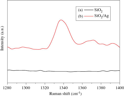
SERS spectra of DTNB. (a) with pure SiO2 powder; (b) with SiO2/Ag composite spheres.
3.6 Electrical conductivity of SiO2/Ag composite spheres
In our work, a four-point probe technique was used to investigate the electrical conductivity of SiO2/Ag composite spheres. Silica powder is used today in a large variety of applications because it is easy to form and has good chemical resistance. However, silica powder is electrically insulating. Composite spheres overcome this shortcoming by coating a layer of silver on the surface of silica [23]. As shown in Figure 7, the current-voltage characteristic (I-V characteristic) of SiO2/Ag composite spheres improves, the reason for which is that the SiO2/Ag composite spheres can increase conductive contact points, forming more conductive channels [24].

I-V characteristics of the pure SiO2 powder and SiO2/Ag composite spheres.
4 Conclusions
In summary, a simple, rapid, and comparatively novel route for the formation of SiO2/Ag core-shell composite spheres has been accomplished. With the aid of pulse plating, neither additional reducing agent nor the core surface modification was needed in this study. According to XRD, SEM, TEM, and EDS, the formation of SiO2/Ag composite spheres has been confirmed. Photoluminescence spectrometer and Raman spectrometer analyses showed these composite spheres had better PL and SERS properties than the pure SiO2 powder. In addition, after coating, the electrical conductivity of SiO2/Ag composite spheres improved. On the basis of the study, the further application on many kinds of composite spheres coated with various metal nanospheres (Au, Pt, Pd, etc.) could be possibly reasonable.
Acknowledgments
The technical support from the Beijing National Center for Electron Microscopy for this research is appreciated. Moreover, the financial support provided by the National Nature Science Foundation of China (Grant No. 51371105) and Educational Commission of Hubei Province of China (Grant No. D20131307) is greatly acknowledged.
References
[1] Luo N, Mao L, Jiang L, Zhan J, Wu Z, Wu D. Mater. Lett. 2009, 63, 154–156.10.1016/j.matlet.2008.09.033Search in Google Scholar
[2] Kundu S, Mandal M, Ghosh SK, Pal T. J. Photochem. Photobiol. A: Chem. 2004, 162, 625–632.10.1016/S1010-6030(03)00398-8Search in Google Scholar
[3] Sun YG, Lei CH. Angew. Chem. Int. Ed. 2009, 48, 6824–6827.10.1002/anie.200902305Search in Google Scholar PubMed
[4] Law WC, Yong KT, Baev A, Hu R, Prasad PN. Opt. Express 2009, 17, 19041–19046.10.1364/OE.17.019041Search in Google Scholar PubMed
[5] Oldenburg SJ, Hale GD, Jackson JB, Halas NJ. Appl. Phys. Lett. 1999, 75, 1063–1065.10.1063/1.124597Search in Google Scholar
[6] Roldán MV, Castro Y, Pellegri N, Durán A. J. Sol-Gel Sci. Tech. 2015, 76, 180–194.10.1007/s10971-015-3765-6Search in Google Scholar
[7] Ma P, Liang F, Diao Q, Wang D, Yang Q, Yang Q, Gao D, Song D, Wang X. RSC Adv. 2015, 5, 32168–32174.10.1039/C5RA04423ESearch in Google Scholar
[8] Huang S, Wen Z, Zhang J, Yang X. Electrochim. Acta 2007, 52, 3704–3708.10.1016/j.electacta.2006.10.044Search in Google Scholar
[9] Simon JD, Peter KS. J. Amer. Chem. Soc. 1982, 104, 6542–6547.10.1021/ja00388a010Search in Google Scholar
[10] Pujari M, Agarwal A, Uppaluri R, Verma A. Appl. Surf. Sci. 2014, 305, 658–664.10.1016/j.apsusc.2014.03.156Search in Google Scholar
[11] Ye X, Zhang C, Xiao X, Cai S. Mater. Lett. 2015, 141, 191–193.10.1016/j.matlet.2014.11.085Search in Google Scholar
[12] Cao H, He J, Deng L, Gao X. Appl. Surf. Sci. 2009, 255, 7974–7980.10.1016/j.apsusc.2009.04.199Search in Google Scholar
[13] Caruso F, Caruso RA, Mohwald H. Science 1998, 282, 1111–1114.10.1126/science.282.5391.1111Search in Google Scholar PubMed
[14] Liu Y, Pan C, Chen W. Mater. Res. Bull. 2008, 43, 3397–3407.10.1016/j.materresbull.2008.02.004Search in Google Scholar
[15] Stöber W, Fink A, Bohn E. J. Colloid Interf. Sci. 1968, 26, 62–69.10.1016/0021-9797(68)90272-5Search in Google Scholar
[16] Juškėnas R, Pakštas V, Sudavičius A, Kapočius V, Karpavičienė V. Appl. Surf. Sci. 2004, 229, 402–408.10.1016/j.apsusc.2004.02.023Search in Google Scholar
[17] Deng Z, Chen M, Wu L. J. Phys. Chem. C 2007, 111, 11692–11698.10.1021/jp073632hSearch in Google Scholar
[18] Li Y, Liu B, Zhang R, Xie ZL, Zhuang Z, Dai JP, Tao T, Zhi T, Zhang GG, Chen P, Ren FF, Zhao H, Zheng YD. J. Appl. Phys. 2015, 117, 153103.10.1063/1.4918555Search in Google Scholar
[19] Jiang R, Li B, Fang C, Wang J. Adv. Mater. 2014, 26, 5274–5309.10.1002/adma.201400203Search in Google Scholar PubMed
[20] Zhang XF, Clime L, Ly HQ, Trudeau M, Veres T. J. Phys. Chem. C 2010, 114, 18313–18317.10.1021/jp1051112Search in Google Scholar
[21] Moskovits M. Rev. Modern Phys. 1985, 57, 783–826.10.1103/RevModPhys.57.783Search in Google Scholar
[22] Kleinman SL, Frontiera RR, Henry A, Dieringer JA, Duyne RPV. Phys. Chem. Chem. Phys. 2013, 15, 21–36.10.1039/C2CP42598JSearch in Google Scholar PubMed
[23] Hu Y, Zhang H, Li F, Cheng X, Chen T. Polym. Test. 2010, 29, 609–612.10.1016/j.polymertesting.2010.03.009Search in Google Scholar
[24] Xu C, Li W, Wei Y, Cui X. Mater. Des. 2015, 83, 745–752.10.1016/j.matdes.2015.06.036Search in Google Scholar
©2017 Walter de Gruyter GmbH, Berlin/Boston
This article is distributed under the terms of the Creative Commons Attribution Non-Commercial License, which permits unrestricted non-commercial use, distribution, and reproduction in any medium, provided the original work is properly cited.
Articles in the same Issue
- Frontmatter
- Original articles
- Wave propagation in functionally graded piezoelectric-piezomagnetic rectangular bars
- Graphene/poly(vinylidene fluoride) dielectric composites with polydopamine as interface layers
- A novel biaxial double-negative metamaterial for electromagnetic rectangular cloaking operation
- Formation of homogenous copper film on MWCNTs by an efficient electroless deposition process
- Nano-SiCp/Al2014 composites with high strength and good ductility
- Microstrip line-fed monopole antenna on an epoxy-resin-reinforced woven-glass material for super wideband applications
- Influence of casting speed on fabricating Al-1%Mn and Al-10%Si alloy clad slab
- Thermal insulating epoxy composite coatings containing sepiolite/hollow glass microspheres as binary fillers: morphology, simulation and application
- Analysis of influence of fibre type and orientation on dynamic properties of polymer laminates for evaluation of their damping and self-heating
- Dynamic stability of nanocomposite viscoelastic cylindrical shells coating with a piezomagnetic layer conveying pulsating fluid flow
- Buckling and layer failure of composite laminated cylinders subjected to hydrostatic pressure
- One-step preparation and characterization of core-shell SiO2/Ag composite spheres by pulse plating
- The failure mechanism of carbon fiber-reinforced composites under longitudinal compression considering the interface
- A thermal-plastic model of friction stir welding in aluminum alloy
- A model for longitudinal tensile strength prediction of low braiding angle three-dimensional and four-directional composites
- Nonlinear stability of shear deformable eccentrically stiffened functionally graded plates on elastic foundations with temperature-dependent properties
- Design and multibody dynamics analyses of the novel force-bearing structures for variable configuration spacecraft