A thermal-plastic model of friction stir welding in aluminum alloy
-
 ,
,

Abstract
A three-dimensional heat transfer model for friction stir welding is presented in this paper. A moving coordinate was introduced to reduce the difficulty of modeling the moving tool. Heat input from the tool shoulder and the tool pin were considered in the model. The plastic deformation heat was introduced into the model, too. It is clear that the heat production increased owing to plastic deformation, and this process depends on the stress level. Temperature measurement experiments were done to validate the calculated results. The calculated results were in good agreement with the experimental results. Preheating the workpiece is beneficial to obtain a good weld seam.
1 Introduction
Friction stir welding (FSW) has emerged as an innovative method for joining low melting-temperature alloys like aluminum (Al) and magnesium (Mg). A good understanding of the heat transfer process in the workpiece can be helpful in evaluating the welding quality [1]. As the tool travels along the joint, the adjoining surfaces are stirred together. There are three distinct regions in the weld joint in FSW: a heat-affected zone (HAZ), a thermo-mechanically affected zone (TMAZ) and a nugget zone (NZ). The majority of heat transfer models for FSW [2], [3], [4], [5], [6] apply Rosenthal and Weld’s [7] framework for a moving point source, with friction from the tool shoulder contributing the dominant heat input. Ulysse [8] extended the framework to introduce a plastic work term. However, the model was still restricted to determining thermal transients around a point source. Liu et al. [9] developed an electrically assisted FSW system, which enables a local electrical current field moving with the FSW tool without requiring the tool to be one of the electrodes. The effectiveness of the electro-plastic effect, which describes a material softening phenomenon during plastic deformation induced by high-density current, was investigated for the FSW of dissimilar Al 6061 alloy to TRIP 780 steel [9]. Sound friction stir welded joints of 6061-T6 aluminum alloy to AZ31B magnesium alloy are obtained using the combination of the intermediate rotation rate of the tool (600–800 rpm) and a low traverse speed (30–60 mm/min) [10]. Heat input in Al-Mg dissimilar metal FSW could be calculated accurately based on measuring the x-axis torque and spindle torque [10]. Because of the differences in friction coefficient, liquation tendency and deformability between Al alloy and Mg alloy, as well as in the extent of mixing, the heat input increased by placing aluminium alloy on the advance side of the tool, the increased rotation rate and traverse speed could decrease heat input. Kuang et al. [11] studied the interlayer of the dissimilar FSW of 2-mm copper plate and 2-mm aluminum plate using 0.2-mm zinc foil as a filler metal with a pinless tool. The macro- and microstructure, heat history of the interlayer under different parameters and the weld properties were investigated [11]. A numerical method based on computational fluid dynamics was employed to quantitatively analyze the thermo-physical phenomena in FSW with two tools of different pin shapes (an axisymmetrical conical tool and an asymmetrical triflat tool) [12]. The total heat generation, heat density and temperature distribution during the welding process with a triflat tool were elucidated and compared with that of the conical tool, and the material flow patterns and deformation regions of various pin orientations were illustrated in detail. The computed thermal cycles and peak temperature values at some locations were in good agreement with the experimentally measured ones [12]. The goal of the current study was to investigate the region under the shoulder where the joint was created and to know how to calculate the heat produced by friction and plastic deformation.
In this model, the friction heat is divided into three parts: (1) the friction heat between the shoulder and the workpiece; (2) the friction between the cylindrical area of the pin and the workpiece; and (3) the friction heat between the bottom area of the pin and the workpiece. The heat produced by plastic deformation around the tool is introduced into the model, too.
2 Experiment of temperature measurement
Two 6063-T6 plates, each with a dimension of 300×110×8 mm, were butt welded in a FSW machine (FSW-3LM-002, China FSW Center, Beijing, China). The tool made of high-speed steel consists of a shoulder and a threading pin with a radius of 12 and 5 mm, respectively. The length of the pin is 7.8 mm in relation to the thickness of the plates. A three-dimensional view of the workpiece and the tool with its boundary conditions is shown in Figure 1. The temperature-dependent material properties of aluminum alloy 6063-T6 were considered during the model development, as shown in Table 1 [13].

Boundary conditions applied on the workpiece.
Physical property of the 6063-T6 aluminum.
| Temperature, °C | 100 | 200 | 300 | 400 | 500 |
| Heat conductivity, W/(m °C) | 180 | 184 | 188 | 192 | 196 |
| Heat capacity, J/(kg °C) | 921 | 1005 | 1047 | 1089 | 1235 |
| Yield stress, MPa | 260 | 221 | 80 | 28 | 5 |
The plates were prepared to measure the temperature at four points using thermocouples enwrapped by ceramic tube. On each plate, two K-type thermocouples of 0.5 mm diameter were welded to the surface. The locations of the thermocouples on the workpiece are shown in Figures 2 and 3.

Thermocouple locations on workpiece.

Thermocouples enwrapped by ceramic tube.
The thermocouples cannot be placed in the thermo-mechanically affected zone (TMAZ) of the weld since the stirring of the tool will destroy it when the tool reaches its location. Transient temperatures were recorded in the four channels during the FSW process. Thermocouples were attached to a system that can sample the temperature data at 50 Hz. The latter, in turn, was attached to a computer with a customized program for recording the temperature data.
3 Thermal model description
The FSW process is divided into the following three periods: (a) the preheating period, (b) the welding period and (c) the tool pull-out period. The time for preheating is 10 s in all. The third period is not considered in the model. Heat is generated because of friction and the plastic deformation at the interface of the tool and the workpiece during the process.
Frictional heat between the tool and the workpiece produces (1) the friction heat between the shoulder and the workpiece; (2) the friction heat between the cylindrical area of the pin and the workpiece; and (3) the friction heat between the bottom area of the pin and the workpiece.
The following assumptions were introduced into the model. (i) There is no material melting during the welding process. (ii) The surface of the shoulder is slick, and it will not affect the plastic flow of the material under the tool. (iii) The radiation heat loss is neglected as it is considerably less compared to the conduction and convection losses.
3.1 Heat transfer model
During the weld period, the tool moves at a constant speed along the joint line. For such a problem, it is convenient to use a moving coordinate system that moves with the tool, instead of using a stationary system. By applying a moving coordinate, it is not necessary to model the complicated stir process near the pin, thus making the model easier to use. The heat transfer control equation for the workpiece in a moving coordinate system with a positive x-direction moving tool can be written as
where T is the temperature, c is the heat capacity, ρ is the density, ν is the tool moving speed, and kx, ky, kz are the heat conductivities, which vary with the temperature in the calculations.
3.1.1 Frictional force in the FSW
When the tool rotates and is inserted into the workpiece, the workpiece endures the pressure force and shearing force, and the temperature of the material goes up to 100s of centigrade and stabilizes. The plastic deformation happens around the pin. Since Coulomb’s law is not suited for calculating the frictional force in the FSW process, the sticking friction law was adopted in this model.
According to the sticking friction law, the raised points on the contact area (microstructure) should be welded with heavy pressure and high temperature. When the contact area moves while the friction is happening, the welded points will be cut and the force that will do the cutting is the frictional force. So, the friction force results from the association of normal force and shearing force.
Based on the common conception of strength [14], the equivalent stress is introduced to calculate the friction force:
where K is the equivalent stress, σ is the compression stress of the workpiece, τ is the shearing stress of the workpiece and α is a constant, which is commonly 9.
When the workpiece yields, the shearing strength is equal to the compression stress multiplied by 0.577, so
The friction force is
where F is the frictional force and A is the actual contact area.
In the FSW process, with a high temperature, the surface of the workpiece appears during the plastic flow, with the actual contact area approaching the contact area of the tool.
3.1.2 Heat frictional force between the tool and the workpiece
Friction heat between the shoulder and the workpiece is crucial to the FSW weld joint. The infinitesimal area model of the shoulder surface is shown in Figure 4. The frictional force of the infinitesimal area is

The multiplication model on the shoulder surface.
where r is the distance from the infinitesimal area to the center of the tool and θ is the central angle of the infinitesimal area.
The work frictional force of the infinitesimal area in one cycle is
And the work frictional force on the interface between the shoulder and the workpiece in one cycle is
where Rt is the radius of the shoulder and Rp is the radius of the pin.
The heat produced by the frictional force between the shoulder and the workpiece in 1 s is
where w is the rotational speed of the tool.
The heat produced between the shoulder and the workpiece is transmitted to the tool and the workpiece at the same time. And because of the different thermophysical properties, the heat that the tool and the workpiece receive is different. The thermal distribution factor decides how much heat the tool and the workpiece receive, respectively, and the factor is
where ρ1 is the density of the workpiece material, λ1 is the coefficient of the thermal conductivity of the workpiece material, c1 is the heat capacity of the workpiece material, ρ2 is the density of the tool material, λ2 is the coefficient of the thermal conductivity of the tool material and c2 is the heat capacity of the tool material.
So, the heat-flow density into the workpiece between the shoulder and the workpiece is
The multiplication model on the cylindrical area of the pin is shown in Figure 5. The heat-flow density into the workpiece between the cylindrical area of the pin and the workpiece is
The multiplication model on the cylindrical area of the pin.
where α is the rate multiplier of the actual area of the threading pin to the cylindrical area.
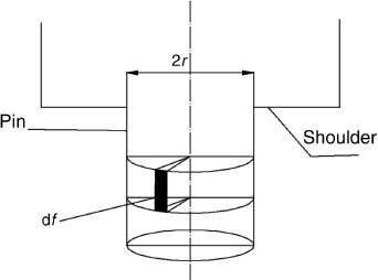
The multiplication model on the bottom area of the pin is shown in Figure 6. The heat-flow density into the workpiece between the bottom of the pin and the workpiece is

The multiplication model on the bottom area of the pin.
3.1.3 Heat input by the plastic deformation
Based on the theory of metal plastic deformation, the energy produced while plastic deformation is happening is converted to potential energy of elastic deformation and to thermal energy of plastic deformation. The former consists of free elastic potential deformation, which emerges before plastic deformation and disappears after unloading, and restraint potential energy, which is generated by distortion of the crystal lattice. After unloading, the restraint potential energy stays in the deformable body and is converted to heat. This is the heat effect of plastic deformation.
In the FSW, plastic deformation is much greater than elastic deformation, and the latter is ignored in the model, which can be built as a rigid-viscoplastic model. From the theory of plasticity, the capacity factor of the plastic deformation of the workpiece is
where σ̅ is the equivalent effective stress and
For aluminum alloy, the ratio of the capacity factor of the plastic deformation converted to heat is about 0.9, so the body heat of plastic deformation in the FSW process is
The plastic flow around the tool is shown in Figure 7. The equivalent effective strain rate is

Plastic flow layer around the tool.
where n is the angular velocity, H is the height of the pin, ϕ is the lead angle of the screw thread in the pin and B is the thickness of the plastic flow around the pin and can be obtained from the constitution diagram of the welding joint.
The equivalent effective stress is [15]
where R is the mole gas constant and T is the temperature.
3.2 Boundary condition
The conduction and convection coefficients on various surfaces play an important role in the determination of the thermal history of the workpiece in FSW. In this model, the boundary condition at the joint line is symmetric, and the interface between two plates in the joint line is considered as thermal insulation. And only one plate is calculated. Figure 1 shows the various boundary conditions applied on the model.
3.2.1 Interface between the tool and the workpiece
The heat flux boundary condition for the interface between the tool and the workpiece is
3.2.2 The convection boundary conditions
Convection at the sides of the workpiece and the tool is represented based on Newton’s law of cooling as
where n is the normal direction vector of boundary Γ, h is the convection coefficient and T0 is the initial temperature, which is room temperature.
3.2.3 Interface between the workpiece and the backplate
Contact conductance at the interface between the workpiece and the backplate has a non-uniform variation, depending on the temperature and pressure at various zones in contact. This contact condition is imposed in the code of the finite element method by introducing a layer of 10 mm thickness with a thermal conductivity equal to that of the steel multiplied by a factor.
The coefficient of heat transmission is [16]
where λ is the thermal conductivity of the steel, t is the thickness of the layer and α is equal to 1 under the tool, lower than 1 behind the tool and equal to 0 elsewhere.
4 Results and discussion
The general-purpose finite element code ANSYS (Pittsburgh, PA, USA) was used for solving the energy equations. The Lagrangian finite element formulation with a nonuniform mesh was used for the model. A higher density of mesh was provided at the surface along the joint line owing to the maximum expected temperature gradient. The density of the mesh gradually decreased, going laterally away from the joint line. A model with the same size as the workpiece was used in the welding.
4.1 Calculated temperature
Figure 8 shows the temperature field in the preheating period (t=10 s) and that in the welding period (t=31 s). The rotation speed was 600 rpm, and the weld speed was 200 mm/min. In Figure 7, the highest temperature was about 400°C, and the material was softened through agitation and extrusion. The isotherm in this period seemed like the shape of the tool, and the highest temperature appeared along the contour of the tool. The main heat production was frictional heat, and the plastic deformation heat was secondary.

The temperature field in the preheating period.
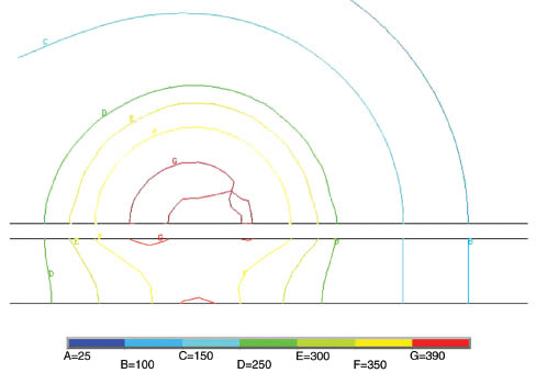
In Figure 9, the highest temperature was about 450°C and the temperature field was steady. In the TMAZ, the isotherm was not circular because the heat produced by plastic deformation was enhanced during the welding. The shape of the isotherm in the TMAZ depended on the combination of friction and plastic deformation, especially in the advance side of the tool. In the thickness section, the temperature at the top was higher than that at the bottom because the heat produced in the interface between the shoulder and the workpiece was greater than in other parts. The local temperature field of TMAZ in the preheating period is shown in Figure 10. The isotherm in the TMAZ was interleaving. This is because the heat input was not enough to form the weld seam. The material could not come into the plastic flow state. If the tool moves at this time, some defects will be found in the weld seam. So, the time for preheating the workpiece is the key to the formation of the weld. It is necessary to allocate enough time to agitate and extrude the material, which can flow in the plastic state.

The temperature field in the weld period.
Local temperature field of TMAZ in the preheating period.
4.2 Experiment validation
The results at the positions of thermocouple A and B in the simulated thermal profile were compared with the experimental results and are shown in Figure 11. It can be seen that the highest temperature attained was almost the same for both process simulations, which compared well with the thermocouple results. The gradient of the temperature that built up in the workpiece, however, was different for both the simulation cases, with the adaptive contact conductance model giving more closely conforming results. Figure 11 shows that the presented heat-transfer model can be applied successfully in predicting the thermal cycles of the workpiece during FSW. By coupling this model to the corresponding microstructure models, the calculated temperature history can also be used in predicting the hardness in the weld zone.

Calculated and measured temperatures at typical measuring points.
5 Conclusions
A three-dimensional transient heat-transfer model, using the description of a rigid-viscoplastic material, was developed in this paper; the calculated results successfully demonstrated the heat transfer process of the workpiece in FSW. The following conclusions can be drawn:
This model can accurately demonstrate the heat-transfer process in FSW. Predicted results were compared with experimental data, and a good agreement was obtained.
The frictional force between the tool and the workpiece cannot be calculated simply by friction factor but requires using the sticking friction law at high temperature, and it results from the association of normal force and shearing force between the tool and the workpiece.
The heat input by the plastic deformation cannot be ignored, as it is important for the temperature in TMAZ, and it may sometimes be the primary heat source in the welding process.
A sufficient time to preheat the workpiece is beneficial to increase the temperature of the workpiece in front of the tool pin, allowing the material to be welded easily.
Acknowledgments
This research was supported by the Foundation of High Level Cultivate Special Project of Shanghai University of Engineering Science (2012gp21), the Natural Science Foundation of China (51375294), the Natural Science Foundation of Shanghai (12ZR1444500), the Research Innovation Project of Shanghai Education Committee (14YZ139) and the Local College Capacity Building of Shanghai Science and Technology Committee (13160501200).
References
[1] Sued MK, Pons D, Lavroff J, Wong EH. Mater. Design 2014, 54, 632–643.10.1016/j.matdes.2013.08.057Search in Google Scholar
[2] Pan W, Li D, Tartakovsky AM. Int. J. Plasticity 2013, 48, 189–204.10.1016/j.ijplas.2013.02.013Search in Google Scholar
[3] Qian J, Li J, Sun F, Xiong J. Scripta Mater. 2013, 68, 175–178.10.1016/j.scriptamat.2012.10.008Search in Google Scholar
[4] Colligan KJ, Mishra RS. Scripta Mater. 2008, 58, 327–331.10.1016/j.scriptamat.2007.10.015Search in Google Scholar
[5] Yang B, Yan J, Sutton MA, Reynolds AP. Mat. Sci. Eng. A. 2004, 364, 55–65.10.1016/S0921-5093(03)00532-XSearch in Google Scholar
[6] Song M, Kovacevic R. Int. J Mach Tools Manu. 2003, 43, 605–615.10.1016/S0890-6955(03)00022-1Search in Google Scholar
[7] Rosenthal D, Weld J. Res. Suppl. 1941, 20, 220–234.10.1213/00000539-194101000-00057Search in Google Scholar
[8] Ulysse P. Int. J. Mach. Tools Manuf. 2002, 42, 1549–1557.10.1016/S0890-6955(02)00114-1Search in Google Scholar
[9] Liu X, Lan S, Ni J. J. Mater Process Tech. 2015, 219, 112–123.10.1016/j.jmatprotec.2014.12.002Search in Google Scholar
[10] Fu B, Qin G, Li F. J. Mater Process Tech. 2015, 218, 38–47.10.1016/j.jmatprotec.2014.11.039Search in Google Scholar
[11] Kuang B, Shen Y, Chen W. Mater. Design 2015, 68, 54–62.10.1016/j.matdes.2014.12.008Search in Google Scholar
[12] Su H, Wu CS, Bachmann M. Mater. Design 2015, 77, 114–125.10.1016/j.matdes.2015.04.012Search in Google Scholar
[13] Brown WF, Jr., Mindlin H, Ho CY. Aerospace Structural Metals Handbook. Purdue University: West Lafayette, 1993.Search in Google Scholar
[14] Jonas JJ, Sellars CM, Tegart WJ. Int. Metall. Rev. 1969, 3, 1–24.10.1179/095066069790138056Search in Google Scholar
[15] Mengjun W, Libin Y. J. Huazhong Univ. Sci. Technol. 2003, 31, 20–22.10.1007/BF02904782Search in Google Scholar
[16] Gallais C, Denquin A. 5th International Friction Stir Welding Symposium, Metz, France, 14–16 September 2004.Search in Google Scholar
©2017 Walter de Gruyter GmbH, Berlin/Boston
This article is distributed under the terms of the Creative Commons Attribution Non-Commercial License, which permits unrestricted non-commercial use, distribution, and reproduction in any medium, provided the original work is properly cited.
Articles in the same Issue
- Frontmatter
- Original articles
- Wave propagation in functionally graded piezoelectric-piezomagnetic rectangular bars
- Graphene/poly(vinylidene fluoride) dielectric composites with polydopamine as interface layers
- A novel biaxial double-negative metamaterial for electromagnetic rectangular cloaking operation
- Formation of homogenous copper film on MWCNTs by an efficient electroless deposition process
- Nano-SiCp/Al2014 composites with high strength and good ductility
- Microstrip line-fed monopole antenna on an epoxy-resin-reinforced woven-glass material for super wideband applications
- Influence of casting speed on fabricating Al-1%Mn and Al-10%Si alloy clad slab
- Thermal insulating epoxy composite coatings containing sepiolite/hollow glass microspheres as binary fillers: morphology, simulation and application
- Analysis of influence of fibre type and orientation on dynamic properties of polymer laminates for evaluation of their damping and self-heating
- Dynamic stability of nanocomposite viscoelastic cylindrical shells coating with a piezomagnetic layer conveying pulsating fluid flow
- Buckling and layer failure of composite laminated cylinders subjected to hydrostatic pressure
- One-step preparation and characterization of core-shell SiO2/Ag composite spheres by pulse plating
- The failure mechanism of carbon fiber-reinforced composites under longitudinal compression considering the interface
- A thermal-plastic model of friction stir welding in aluminum alloy
- A model for longitudinal tensile strength prediction of low braiding angle three-dimensional and four-directional composites
- Nonlinear stability of shear deformable eccentrically stiffened functionally graded plates on elastic foundations with temperature-dependent properties
- Design and multibody dynamics analyses of the novel force-bearing structures for variable configuration spacecraft