Formation of homogenous copper film on MWCNTs by an efficient electroless deposition process
-
Abolfazl Alizadeh Sahraei
 ,
Hamidreza Naser Saeed
,
Hamidreza Naser Saeed

Abstract
In this study, copper-coated multi-walled carbon nanotubes (MWCNTs) were prepared using electroless deposition process with an efficient bath composition. As-received MWCNTs underwent acid treatment and subsequent sensitization with tin and activation with palladium before the copper coating process. The electroless deposition process was performed in a bath, which contained copper sulphate pentahydrate as a copper precursor, potassium sodium tartrate as a complexing agent, and formaldehyde as a reducing agent. Surface modifications of MWCNTs were studied by Fourier transform infrared spectroscopy, imaging techniques (scanning electron microscopy, transmission electron microscopy), and X-ray diffraction. On the basis of the results, it was observed that the coating layer covers most surfaces of the nanotubes. Furthermore, copper oxide is also deposited on the surfaces of MWCNTs. The total amount of metals after each sensitization, activation, and metallization step was determined by thermo gravimetric method and induced coupled plasma atomic emission spectroscopy. Coating of MWCNTs was accomplished successfully through adjusting proper chemical ratios and concentrations. The calculated bath efficiency was about 99%.
1 Introduction
The superior mechanical, thermal, and electrical properties of carbon nanotubes (CNTs) have made them attractive for various applications, including filler materials in composites, energy storage materials, nano-probes, and sensors [1], [2], [3], [4], [5], [6], [7]. Regarding high Young’s modulus of multi-walled CNTs (MWCNTs) [8], they are potential materials to enhance strength of composites impressively; however, application of CNTs in composite fabrication encounters several challenges, which are mainly due to the non-wetting nature of CNTs, their tendency to agglomeration, and formation of clusters by Van der Waals forces [9]. In this regard, appropriate preparation of composite and modification of CNTs are crucial. Chemical modifications such as oxidation by mineral acids or plasma functionalization that introduce functional groups onto the surface of CNTs can improve interactions between polymer matrix and CNTs as the reinforcement [10], [11], [12], [13], [14]. In metal matrix composites (MMCs), although functionalization has a positive impact [15], CNT coating of metals may be a reasonable way to achieve high-strength interfacial bonding [16], [17], [18], [19]. The coated CNTs are a reasonable selection as the precursor powder for metal matrix-carbon nanotube (MM-CNT) composite structures, processed through a powder metallurgy route. Kim et al. [18] fabricated CNT-reinforced copper matrix (CNT/Cu) nanocomposites by pre-coating of single-wall CNTs with nickel. They mechanically mixed the powders and consolidated the nanocomposites by hot press sintering. On the basis of the results, slight decreases of electrical and thermal conductivity besides significant mechanical improvement were observed. Daoush et al. [17] evaluated mechanical and electrical properties of CNT/Cu nanocomposites prepared by electroless copper coating and spark plasma sintering. The results revealed that using electroless coating technique in fabricating CNT/Cu nanocomposites considerably improves mechanical properties, but a drop of more than 20% in electrical conductivity is also observed by addition of 5 vol.% CNT. Rajkumar and Aravindan [20] investigated tribological properties of CNT/Cu nanocomposites using copper-coated CNTs. The results showed better tribological properties of coated composites as compared to the unreinforced copper. The improvement is attributed to the high cohesion strength of the reinforcement with matrix.
Indeed, pre-coating of CNTs with a thin layer of metal improves properties of MM-CNT composite because of the following: one is increasing density of reinforcement, which facilitates dispersion quality of constituent materials, and the other is enhancing interfacial bonding of matrix and reinforcement by improving surface reactivity of CNTs, which in turn leads to a better load transfer efficiency between two phases at the CNT/metal interface [21].
As previous studies indicate, limited methods such as electrochemical deposition [22], electroless deposition [23], [24], molecular-level mixing [16], and chemical/physical vapor deposition [25] have been applied to metal coating of CNTs. Among the aforementioned methods, the electroless deposition technique is of high importance because of its simplicity and higher efficiency. Also, the method has been used to deposit various elements such as copper [24], nickel [26], silver [27], and cobalt [23] onto CNTs.
Low chemical reactivity of CNTs necessitates several treatments before the coating process. Oxidation, sensitization, and activation of surface are necessary for a dense coating of CNTs. These surface treatments can also increase the wettability to keep CNTs in the suspension and to modify their surface charge to reduce tendency of agglomeration. Sensitization and activation of CNTs, which involve the adsorption of tin and palladium particles, could be achieved either in one step [28] or in two steps [29]. The sensitization and activation processes play significant roles in the initiation of electroless metallization on any kind of non-metallic species [30].
The deposition rate and deposit properties of electroless plating mainly depend on complexing agent, reducing agent, ratio of complexing agent to copper source, bath temperature, and pH. Also, using ultrasonic waves enhances adsorption of particles in each step of the coating procedure [31]. Concentration of the complexing agent is also important for preventing the precipitation of metal ions in solution. Besides, it helps the metal ions to participate in deposition on the substrate [32].
To the best knowledge of the authors, very few researches have reported the coating procedure of CNTs, and detailed information on synthesis and characterization of coated CNTs is lacking. In the present work, copper-coated CNTs are synthesized in an efficient electroless deposition bath, and the precise chemical composition of the composite is measured and reported. Copper-coated CNTs are potential materials for reinforcing MMCs with higher sintering temperatures. Our experimental results on copper and aluminum matrix composite using the copper-coated CNTs have been published in [33], [34].
2 Materials and methods
MWCNTs grade of <15 μm length and ~50 nm diameter with purity of ~95% were supplied from Shenzhen Co. Ltd. All materials composed of highly pure chemicals were provided from Daejung Co. Ltd. (Siheung, South Korea).
The functionalization of the MWCNTs were carried out using 10.0 m HNO3 solution for 2 h at 80°C under reflux condition after being sonicated at room temperature for 15 min. The solution was then centrifuged, and its solid content was filtered and washed several times in deionized water until the pH of the solution approached neutral values. The MWCNTs were finally dried in a vacuum oven at 70°C overnight. Prior to electroless plating, acidified MWCNTs were sensitized and activated by means of the following processes. A solution consisting of 0.1 m SnCl2.2H2O and 0.1 m HCl was used for sensitization of MWCNTs by 30 min of sonication. In order to prevent Sn(OH)Cl formation in the solution, HCl molar concentration should typically be equal to or greater than SnCl2. In the activation step, sensitized MWCNTs were stirred in a 0.0025 m solution of PdCl2, and in 0.25 m of HCl for 30 more minute by sonication. MWCNTs were washed by deionized water and separated from medium by centrifugation.
Table 1 shows the copper bath composition in the electroless plating procedure. Along with a specified ratio of copper sulphate pentahydrate as a source of copper, potassium sodium tartrate (Rochelle salt) as a complexing agent, and formaldehyde as a reducing agent, 0.2 g of the activated MWCNTs was added into 100 ml of deionized water in ambient temperature. The pH of the solutions was adjusted in the range of 12.5–12.8 using sodium hydroxide solution. MWCNTs and all of the chemicals, except formaldehyde, were mixed by sonication. Formaldehyde was then added, and after about 2 min, the electroless coating reactions were initiated by emergence of hydrogen bubbles in the solution. Simultaneously, the pH drop should be recovered by adding sodium hydroxide solution. Then, the deposited MWCNTs were washed with deionized water and dried at 70°C. The schematic of the whole process is illustrated in Figure 1.
Composition of copper electroless deposition bath.
| Compound | Concentration |
|---|---|
| CuSO4.5H2O | 0.1 mol/l |
| KNaC4H4O6·4H2O | 0.5 mol/l |
| HCHO (37%) | 1% vol. |
| NaOH | – |
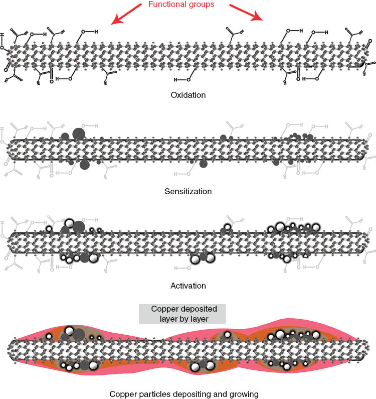
Schematic fabrication process steps of the copper electroless deposition.
The functional groups on the surface of the oxidized MWCNTs were detected by Bruker Vector 33 Fourier transform infrared spectroscopy (FTIR) instrument. The acid-treated MWCNTs were heated at 90°C for an hour in order to remove any possible moisture before FTIR characterization. The morphologies of the deposited MWCNT composites were characterized by transmission electron microscopy (TEM; Q1 Philips EM208) and scanning electron microscopy (SEM; Vega II TESCAN) operated at 100 and 15 kV, respectively. The quantitative elemental analysis was accomplished by energy-dispersive X-ray spectroscopy (EDX; SAMx). The crystalline structure of metal deposits was analyzed using Philips X’Pert X-ray diffractometer (XRD). The average crystallite size of the coated metals was calculated by Scherrer equation from the (111) diffraction peak. Variations of pH in the electroless bath solution during the deposition process were recorded by a digital pH meter model 56502 Az instrument Co. Ltd. Thermo gravimetric analysis (TGA) was performed in air at a heating rate of 10°C/min from ambient temperature to 800°C to quantify the mass percentage of metal particles on the surface of MWCNTs (TG/DTA 6300, SII Nanotechnology, Japan). More accurate mass percentages of tin, palladium, and copper were measured by inductively coupled plasma atomic emission spectroscopy (ICP-AES, Varian 735-ES). Sample preparation for the ICP-AES analysis was carried out by dissolving 0.1 g of powder in HNO3 at 120 to 150°C for about 45 min to 1 h. Following the separation of coated MWCNTs from suspension, concentration of copper in the filtered solution was calculated using atomic absorption spectroscopy (AAS) in order to measure copper consumption efficiency of electroless bath.
3 Results and discussion
Nitric acid treatment, which has been used for functionalization, is expected to produce carboxylic (COOH) and/or hydroxyl groups (OH) on the surface of MWCNTs [35], [36]. These functional groups improve the solubility of MWCNTs in aqueous solution and are suitable nucleation sites on the MWCNT surface to aid metal deposition [37], [38]. The FTIR spectra of as-received and oxidized MWCNTs are illustrated in Figure 2. The FTIR spectrum of oxidized MWCNTs (Figure 2B) indicates intensive band at wavenumbers ~3440 cm-1, which is attributed to -OH stretching vibration of the hydroxyl groups and/or -OH in carboxyl groups, whereas the bands in the range of 850–1300 cm-1 prove the presence of C-O bonds in different chemical surroundings [39]. In addition to the mentioned peaks, two other major peaks at about 1630 and 1400 cm-1 correspond to C=O bands in ketone/quinone groups and O-H bending in carboxylic acids, respectively [40], [41]. Furthermore, the appearance of the peak at wavenumbers ~3440 cm-1 in FTIR spectrum of as-received MWCNTs might be due to the partial oxidation of the surfaces of MWCNTs during the purification steps performed by the manufacturer. The peak at ~2350 cm-1 may also be associated with the presence of CO2 in the air.
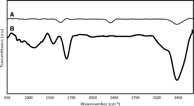
FTIR spectra of (A) as-received MWCNTs and (B) 2-h 10.0 m HNO3 treatment at 80°C.
The SEM images and EDX spectra of as-received and treated MWCNTs besides TEM image of coated MWCNTs are shown in Figure 3. As it can be seen from Figure 3A, the average diameters of as-received MWCNTs were about 50 nm, and they were twisted and entangled with each other in the form of clusters. Acid treatment is essential to unravel the twisting and to facilitate the dispersion of MWCNTs in aqueous solution. Sensitized MWCNTs and the deposited tin particles on their exterior surface are shown in Figure 3B. Figure 3C and D shows the SEM image and EDX spectrum of activated MWCNTs, respectively. Sn2+, which was deposited in the sensitization step, reduced the Pd2+ to Pd colloid nuclei that served as metallic active centers for growing copper seed layer. The EDX result confirms the presence of tin, palladium, and oxygen on the MWCNTs surface in this step. The existence of oxygen may be related to the oxygen-containing functional groups that originated from the oxidation treatment. Morphology of copper-coated MWCNTs is investigated in Figure 3E. As it can be seen, the metallic particles cover most surfaces of the nanotubes. The EDX pattern in Figure 3F shows the presence of carbon, copper, oxygen, and a small amount of tin. Here, the observed oxygen may be attributed to simultaneous electroless coating deposition of copper and copper oxide on the MWCNTs. Precise TEM observation (Figure 3G) also confirms that the metallic copper is deposited along the exterior surfaces of a single MWCNT. Better surface treatment produces uniform metallic coating on CNTs [37].
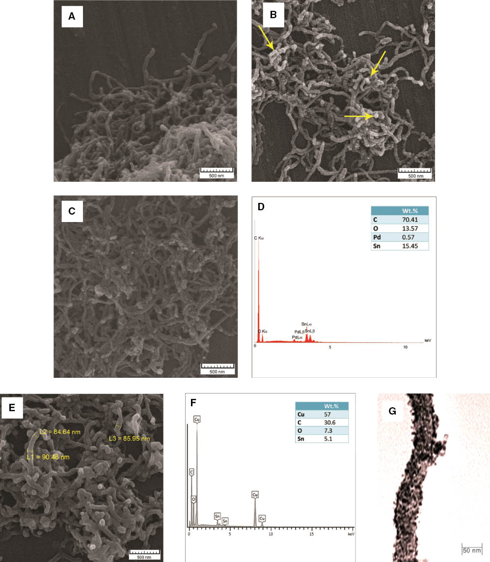
SEM micrographs of (A) as-received MWCNTs, (B) sensitized MWCNTs, (C) activated MWCNTs, (E) copper-coated MWCNTs. EDX spectrum of (D) activated MWCNTs and (F) copper-coated MWCNTs. (G) TEM observation of a single-coated MWCNT.
The crystalline phase of copper-coated MWCNTs was analyzed via the XRD pattern, as can be seen in Figure 4. Analysis of the XRD pattern proves the existence of metallic copper and copper oxide in the deposited layer. The peaks at 43.3, 50.4, 74.1, and 89.9° 2θ are assigned to the (111), (200), (220), and (311) planes of the face-centered cubic crystal structure of copper metal. On the other hand, the peaks at 36.4, 42.3 and 61.3° 2θ correspond to the (111), (200), and (220) planes of copper oxide in the form of Cu2O. Formation of the Cu2O phase can be explicated via potential-pH equilibrium diagram. Theoretically, for pH lower than 5, Cu2O phase formation possibility is zero. Whenever the pH increases to alkaline solution, the possibility of Cu2O formation increases [32]. It is worth mentioning that chemically oxygen atoms present at the Cu-CNT interface is the key factor to both uniform dispersion and strong interfacial bonding of constituent materials [21], [42]. The average crystallite sizes of the metallic copper and copper oxide, calculated by the Scherrer equation, are about 19.17 and 23.41 nm, respectively.
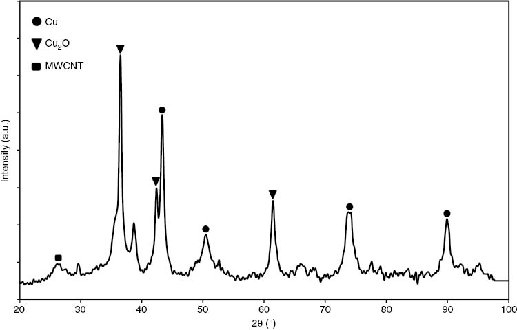
XRD pattern of coated MWCNTs.
Among the parameters affecting the electroless deposition process, the pH value of the electroless bath solution is the most important parameter of the experimental procedure [43]. As our experiments show, in pH values smaller than 12, no chemical deposition reactions occur after 30 min of reductant addition, whereas for the pH values in the range of 12.5–12.8, the deposition process starts in about 2 min. The maximum rate of deposition for the tartrate solution is achieved at pH of 12.8 [44]. The overall reaction for electroless copper deposition with formaldehyde as a reducing agent is:
The reaction reveals that hydrogen gas bubbles on the surface of solution and pH drop are the signs of deposition reactions’ initiation. The obtained results indicate that the deposition process stops when the pH value approaches 10.5, and consequently additional sodium hydroxide solution is required. When blue color of electroless bath solution caused by copper salt vanishes, electroless copper deposition reaction is finished.
Figure 5 represents TGA and differential thermal analysis (DTA) profiles of the copper-coated MWCNTs. The mass loss below ~140°C is due to the release of possible adsorbed gases and moisture on the surface of MWCNTs. Decomposition of oxygen-containing functional groups proceeds in the temperature range of 140–350°C. Total weight loss percentages for these two temperature regions were 3.3 and 5.3 wt.%, respectively. As shown in the DTA profile, the MWCNT weight loss starts at about 350°C, and two stepwise declines in weight occur at temperatures of about 385 and 410°C. Because of the layer-by-layer configuration of graphite sheets in MWCNTs, the oxidation rate of nanotubes is slower than the oxidation rate of amorphous carbon [45]. The two peaks in the DTA of MWCNTs could be attributed to the oxidation temperature of amorphous and crystalline carbon, respectively [13]. According to the aforementioned explanations, MWCNTs have less than 6 wt.% amorphous carbon. The MWCNTs oxidation finishes at near 500°C. At temperatures higher than 500°C, the remaining mass, which is 62 wt.% of the total sample weight, is attributed to deposited metals (Cu, Sn, and Pd), Cu2O, and catalyst nanoparticles used in synthesis of MWCNTs.
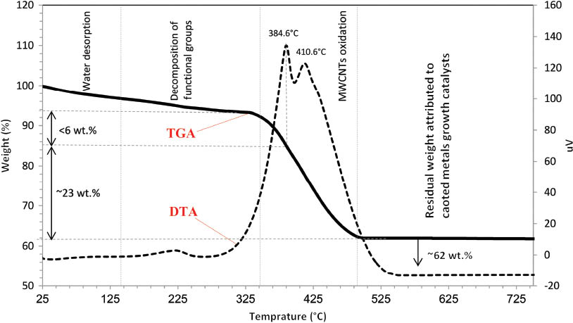
TGA/DTA profiles of MWCNTs coated by copper.
Table 2 shows the concentration of metal particles deposited on MWCNTs in each step measured by ICP-AES analysis. Decreasing amounts of Sn and Pd at the final step may be due to the weak adhesion of some of these particles on the MWCNT surface. These particles may be removed from the substrate by washing. Indeed, Sn2+ has two functions: reduction of Pd ions, and adhesion to MWCNTs surface and the subsequent adhesion of palladium to the substrate [24]. The results achieved by the ICP-AES analysis are in good agreement with TGA. The higher solid content of the sample measured by TGA is about 4 wt.% that may attribute to the remainder oxygen and catalyst particles used in MWCNT synthesis procedures.
Concentration of metal particles deposited on MWCNTs in sensitization, activation, and electroless copper deposition steps.
| Sample | Sn (%wt) | Pd (%wt) | Cu (%wt) |
|---|---|---|---|
| Sensitized MWCNT | 0.2 | – | – |
| Activated MWCNT | 0.16 | 0.27 | – |
| Copper-coated MWCNT | 0.1 | 0.12 | 58.2 |
The concentration of the remaining copper ions in the solution was 14.1 mg/l measured by AAS. That is, more than 99.5% of available copper was deposited on the MWCNTs surface. This remarkable efficiency is likely attributed to the well-adjusted ratio of complex agent to copper source, the efficient functionality of selected complex agent, and the use of ultrasonic waves.
4 Conclusions
Copper-coated MWCNTs were successfully synthesized using nitric acid treatment, separate sensitization and activation solutions, and electroless deposition process. The results show that the selection of proper reactants and their concentrations in the electroless bath, ratio of complexing agent to copper precursor, pH value of about 12.8, and the use of ultrasonic waves are essential considerations for achieving an efficient electroless process. Consumption of more than 99.5 wt.% of available copper besides fast initiation of deposition reactions also prove the high efficiency of the process. Crystalline phase characterization of the coated layer revealed that copper oxide also deposited on MWCNTs. On the basis of the experiments, it was inferred that the measured weight percentages of deposited metals are advantageous data for researchers who use MWCNTs as reinforcement materials in MMCs. In the future, the authors will take advantage of the copper-coated MWCNTs in polymeric matrices to fully investigate the electrical and thermal properties of the final composite.
Acknowledgments
The authors would like to acknowledge the Iran National Science Foundation (INSF) for funding this project.
References
[1] Ajayan P, Zhou O. Carbon Nanotubes 2001, 391–425.10.1007/3-540-39947-X_14Search in Google Scholar
[2] Deng F, Zheng QS, Wang QS, Nan CW. Appl. Phys. Lett. 2007, 90, 021914-021914-021913.10.1063/1.2430914Search in Google Scholar
[3] Liang X, Wang S, Duan X, Zhang Z, Chen Z, Zhang J, Peng L. J. Nanosci. Nanotechnol. 2007, 7, 4–5.10.1166/jnn.2007.340Search in Google Scholar
[4] Baniassadi M, Laachachi A, Makradi A, Belouettar S, Ruch D, Muller R, Garmestani H, Toniazzo V, Ahzi S. Thermochi. Acta 2011, 520, 33–37.10.1016/j.tca.2011.02.037Search in Google Scholar
[5] Asiaei S, Khatibi AA, Baniasadi M, Safdari M. J. Reinf. Plast. Compos. 2010, 29, 818–829.10.1177/0731684408100701Search in Google Scholar
[6] Ghazavizadeh A, Baniassadi M, Safdari M, Atai A, Ahzi S, Patlazhan S, Gracio J, Ruch D. J. Comput. Theor. Nanosci. 2011, 8, 2087–2099.10.1166/jctn.2011.1930Search in Google Scholar
[7] Li DS, Baniassadi M, Garmestani H, Ahzi S, Reda Taha MM, Ruch D. J. Comput. Theor. Nanosci. 2010, 7, 1462–1468.10.1166/jctn.2010.1504Search in Google Scholar
[8] Lu JP. Phys. Rev. Lett. 1997, 79, 1297–1300.10.1103/PhysRevLett.79.1297Search in Google Scholar
[9] Agarwal A, Bakshi SR, Lahiri D. Carbon Nanotubes Reinforced Metal Matrix Composites, CRC Press Taylor & Francis Group: Boca Raton, 2011.Search in Google Scholar
[10] Ávila-Orta CA, Cruz-Delgado CA, Neira-Velázquez MG, Hernández-Hernández E, Méndez-Padilla MG, Medellín-Rodríguez FJ. Carbon 2009, 47, 1916–1921.10.1016/j.carbon.2009.02.033Search in Google Scholar
[11] Luo Y, Zhao Y, Cai J, Duan Y, Du S. Mater. Des. 2012, 33, 405–412.10.1016/j.matdes.2011.04.033Search in Google Scholar
[12] Meng L, Fu C, Lu Q. Prog. Nat. Sci. 2009, 19, 801–810.10.1016/j.pnsc.2008.08.011Search in Google Scholar
[13] Naseh MV, Khodadadi AA, Mortazavi Y, Pourfayaz F, Alizadeh O, Maghrebi M. Carbon 2010, 48, 1369–1379.10.1016/j.carbon.2009.12.027Search in Google Scholar
[14] O’Connell MJ, Boul P, Ericson LM, Huffman C, Wang Y, Haroz E, Kuper C, Tour J, Ausman KD, Smalley RE. Chem. Phys. Lett. 2001, 342, 265–271.10.1016/S0009-2614(01)00490-0Search in Google Scholar
[15] Sahraei AA, Fathi AA, Givi MKB, Boroun S, Pashaei MH. J. Compos. Mater. 2014, 48, 3485–3497.10.1177/0021998313510333Search in Google Scholar
[16] Cha SI, Kim KT, Arshad SN, Mo CB, Hong SH. Adv. Mater. 2005, 17, 1377–1381.10.1002/adma.200401933Search in Google Scholar
[17] Daoush WM, Lim BK, Mo CB, Nam DH, Hong SH. Mater. Sci. Eng. A 2009, 513–514, 247–253.10.1016/j.msea.2009.01.073Search in Google Scholar
[18] Kim C, Lim B, Kim B, Shim U, Oh S, Sung B, Choi J, Ki J, Baik S. Synth. Met. 2009, 159, 424–429.10.1016/j.synthmet.2008.10.017Search in Google Scholar
[19] Lin CB, Chang Z-C, Tung YH, Ko Y-Y. Wear 2011, 270, 382–394.10.1016/j.wear.2010.11.010Search in Google Scholar
[20] Rajkumar K, Aravindan S. Wear 2011, 270, 613–621.10.1016/j.wear.2011.01.017Search in Google Scholar
[21] Kim KT, Cha SI, Gemming T, Eckert J, Hong SH. Small 2008, 4, 1936–1940.10.1002/smll.200701223Search in Google Scholar
[22] Quinn BM, Dekker C, Lemay SG. J. Am. Chem. Soc. 2005, 127, 6146–6147.10.1021/ja0508828Search in Google Scholar
[23] Chen X, Xia J, Peng J, Li W, Xie S. Compos. Sci. Technol. 2000, 60, 301–306.10.1016/S0266-3538(99)00127-XSearch in Google Scholar
[24] Wang F, Arai S, Endo M. Electrochem. Commun. 2004, 6, 1042–1044.10.1016/j.elecom.2004.08.007Search in Google Scholar
[25] Knez M, Nielsch M, Niinistö L. Adv. Mater. 2007, 19, 3425–3438.10.1002/adma.200700079Search in Google Scholar
[26] Sahoo P, Das SK. Mater. Des. 2011, 32, 1760–1775.10.1016/j.matdes.2010.11.013Search in Google Scholar
[27] Chin KC, Gohel A, Chen WZ, Elim HI, Ji W, Chong GL, Sow CH, Wee ATS. Chem. Phys. Lett. 2005, 409, 85–88.10.1016/j.cplett.2005.04.092Search in Google Scholar
[28] Ang LM, Hor TSA, Xu GQ. Chem. Mater. 1999, 11, 2115–2118.10.1021/cm990078iSearch in Google Scholar
[29] Ang LM, Hor TSA, Xu GQ, Tung CH, Zhao SP, Wang JLS. Carbon 2000, 38, 363–372.10.1016/S0008-6223(99)00112-8Search in Google Scholar
[30] Xu L, Liao J, Huang L, Ou D, Guo Z, Zhang H, Ge C, Gu N, Liu J. Thin Solid Films 2003, 434, 121–125.10.1016/S0040-6090(03)00274-8Search in Google Scholar
[31] Peng Y, Chen Q. Colloids Surf. A 2009, 342, 132–135.10.1016/j.colsurfa.2009.04.030Search in Google Scholar
[32] Bindra P, White JR. Fundamental aspects of electroless copper plating. In Electroless Plating Fundamentals & Applications, Mallory GO, Hajdu JB, Eds., William Andrew/Noyes: New York, 1990, pp. 289–375.Search in Google Scholar
[33] Alizadeh Sahraei A, Fathi A, Besharati Givi M, Pashaei M. Appl. Phys. A 2014, 116, 1677–1686.10.1007/s00339-014-8300-zSearch in Google Scholar
[34] Torabi Merajin M, Mosavi Mashhadi M, Alizadeh Sahraei A. J. Compos. Mater. 2013.Search in Google Scholar
[35] Kuznetsova A, Popova I, Yates JT Jr, Bronikowski MJ, Huffman CB, Liu J, Smalley RE, Hwu HH, Chen JG. J. Am. Chem. Soc. 2001, 123, 10699–10704.10.1021/ja011021bSearch in Google Scholar PubMed
[36] Yu Z, Brus LE. J. Phys. Chem. A 2000, 104, 10995–10999.10.1021/jp002197nSearch in Google Scholar
[37] Imam MA, Zeng Q, Bayazitoglu Y, Wilson K, Barrera EV, Luna J. Mater. Sci. Forum 2007, 655–658.10.4028/www.scientific.net/MSF.561-565.655Search in Google Scholar
[38] Rao GP, Lu C, Su F. Sep. Purif. Technol. 2007, 58, 224–231.10.1016/j.seppur.2006.12.006Search in Google Scholar
[39] Stobinski L, Lesiak B, Kövér L, Tóth J, Biniak S, Trykowski G, Judek J. J. Alloys Compd 2010, 501, 77–84.10.1016/j.jallcom.2010.04.032Search in Google Scholar
[40] Goyanes S, Rubiolo GR, Salazar A, Jimeno A, Corcuera MA, Mondragon I. Diamond Relat. Mater. 2007, 16, 412–417.10.1016/j.diamond.2006.08.021Search in Google Scholar
[41] Terzyk AP, Gauden PA, Kowalczyk P. Carbon Materials: Theory and Practice, Research Signpost, Kerala, India, 2008.Search in Google Scholar
[42] Park M, Kim B-H, Kim S, Han D-S, Kim G, Lee K-R. Carbon 2011, 49, 811–818.10.1016/j.carbon.2010.10.019Search in Google Scholar
[43] Xu C, Wu G, Liu Z, Wu D, Meek TT, Han Q. Mater. Res. Bull. 2004, 39, 1499–1505.10.1016/j.materresbull.2004.04.021Search in Google Scholar
[44] Paunovic M. Electroless deposition of copper. In Modern Electroplating, Schlesinger M, Paunovic M, Eds., John Wiley & Sons Inc.: Hoboken, NJ, 2010, pp. 433–446.10.1002/9780470602638Search in Google Scholar
[45] Maghrebi M, Khodadadi AA, Mortazavi Y, Mhaisalkar S. Appl. Surf. Sci. 2009, 255, 7243–250.10.1016/j.apsusc.2009.03.074Search in Google Scholar
©2017 Walter de Gruyter GmbH, Berlin/Boston
This article is distributed under the terms of the Creative Commons Attribution Non-Commercial License, which permits unrestricted non-commercial use, distribution, and reproduction in any medium, provided the original work is properly cited.
Articles in the same Issue
- Frontmatter
- Original articles
- Wave propagation in functionally graded piezoelectric-piezomagnetic rectangular bars
- Graphene/poly(vinylidene fluoride) dielectric composites with polydopamine as interface layers
- A novel biaxial double-negative metamaterial for electromagnetic rectangular cloaking operation
- Formation of homogenous copper film on MWCNTs by an efficient electroless deposition process
- Nano-SiCp/Al2014 composites with high strength and good ductility
- Microstrip line-fed monopole antenna on an epoxy-resin-reinforced woven-glass material for super wideband applications
- Influence of casting speed on fabricating Al-1%Mn and Al-10%Si alloy clad slab
- Thermal insulating epoxy composite coatings containing sepiolite/hollow glass microspheres as binary fillers: morphology, simulation and application
- Analysis of influence of fibre type and orientation on dynamic properties of polymer laminates for evaluation of their damping and self-heating
- Dynamic stability of nanocomposite viscoelastic cylindrical shells coating with a piezomagnetic layer conveying pulsating fluid flow
- Buckling and layer failure of composite laminated cylinders subjected to hydrostatic pressure
- One-step preparation and characterization of core-shell SiO2/Ag composite spheres by pulse plating
- The failure mechanism of carbon fiber-reinforced composites under longitudinal compression considering the interface
- A thermal-plastic model of friction stir welding in aluminum alloy
- A model for longitudinal tensile strength prediction of low braiding angle three-dimensional and four-directional composites
- Nonlinear stability of shear deformable eccentrically stiffened functionally graded plates on elastic foundations with temperature-dependent properties
- Design and multibody dynamics analyses of the novel force-bearing structures for variable configuration spacecraft