Abstract
In this paper, the effect of casting speed on fabricating Al-1%Mn and Al-10%Si alloy clad slab was investigated. Before the trials with the semi-continuous casting process were conducted, a series of simulation with the engineering software FLUENT was made to forecast the influence of the casting speed on the temperature field and the liquid fraction of the clad slab. The simulation results indicated that the increase of the casting speed reduces the time in the cooling zone, thus the thickness of the Al-1%Mn solidification shell under the dividing plate gets thinner. Based on the simulation results, the Al-1%Mn alloy and Al-10%Si alloy clad slab was successfully produced by semi-continuous casting process. The interface of clad ingots was investigated by methods of metallographic and electron probe microanalysis. The tests on the interface confirmed the simulation results and showed that a clad slab of two different aluminum alloys with excellent metallurgical bonding was achieved by semi-continuous casting. According to the result of the tensile tests, the strength of the specimens remains at 110 MPa, and the fracture position located in the Al-1%Mn alloy indicates that the strength of the interface is higher than that of the Al-1%Mn alloy.
1 Introduction
Clad slab has become a favorite topic in the materials field because it possesses excellent physical, chemical and mechanical properties, which a single alloy does not have [1], [2], [3], [4]. Clad metals are widely used in many fields, such as aerospace, petroleum, chemical, automobile and shipbuilding industries. There have been numerous publications over the last 10 years on the need for clad materials. Clad materials can be fabricated by clad rolling [5], [6], hot-extruding [7], [8], explosive welding [9], [10], laser cladding [11], [12] and continuous casting [13]. Researchers are paying more attention to reduce total manufacturing costs and improve the interface bonding strength of clad materials. Continuous casting is an ideal method for producing clad slab, which includes inversion casting [13], double-stream-pouring continuous casting [14], direct-chill semi-continuous casting [15], the Novelis Fusion™ process [16] and so on. With continuous casting, the two liquid metals enter in contact in the mold pool directly to gain a clean, non-pollution, high bonding strength cladding interface. Therefore, the problem of low bonding strength can be solved [17]. In addition, high production efficiency and low cost of production are also advantages of continuous casting. Furthermore, the clad slab can be produced on the existing direct water-cooled continuous casting production lines. The energy consumption can be reduced dramatically. In essence, continuous casting and semi-continuous casting are two similar fabricating methods. Continuous casting was invented after the invention of semi-continuous casting in the 1950s; the main difference between these two methods is the ingot length. The ingots gained from continuous casting are much longer than those of semi-continuous casting. So the equipment for semi-continuous casting is simpler and more suitable for laboratory conditions.
The Al-1%Mn alloy (in wt.%, unless otherwise stated) is an excellent corrosion resistance alloy, but its strength is low. The Al-10%Si alloy has a high strength but poor corrosion resistance. The Al-10%Si alloy with Al-1%Mn alloy cladding on it can combine their advantages, and it can be widely applied to many fields, especially to various heat exchangers.
In this study, the clad slab of Al-10%Si alloy and Al-1%Mn alloy was fabricated by semi-continuous casting. Before the semi-continuous casting process, the fabricating process under different casting speed was simulated and the influence of different casting speed on the clad slab solidification was discussed. The microstructure and solute distribution were observed, and the mechanical properties were measured.
2 Materials and methods
2.1 Semi-continuous casting process
Figure 1 shows the schematic of the experimental apparatus. The water-cooled stainlessness steel dividing plate divides the mold into two sections, and the water flow in it is controllable. The lower part on the left side of the dividing plate acts as an inner mold wall; the bottom of the dividing plate and the Al-10%Si side of the dividing plate are totally heat insulated. During experiment, the Al-1%Mn and Al-10%Si alloys were melted in their respective radiation furnaces. When the temperature of Al-1%Mn reached 983 K, the melt was poured into the left section of the mold. Once the bottom die was drawn, the Al-10%Si melted at 943 K was poured into the right section of the mold to contact with the Al-1%Mn solidification shell below the dividing plate, and the critical process parameters were adjusted to maintain an excellent metallurgical bonding at the interface during the steady state of the semi-continuous casting. The critical process parameters are listed in Table 1.
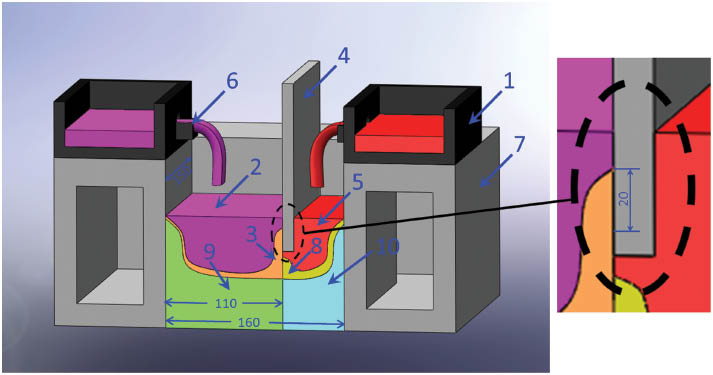
One-half of a symmetrical schematic illustration of continuous casting of clad slab: (1) melt launder, (2) Al-1%Mn alloy melt, (3) Al-1%Mn alloy solidified shell, (4) water-cooled dividing plate, (5) Al-10%Si alloy melt, (6) sprues, (7) mold, (8) semi-solid Al-10%Si alloy, (9) interface, (10) bimetal slab.
Experimental parameters of the semi-continuous casting.
| No. | Dividing plate cooling water flow (l·h-1) | Casting speed (mm·min-1) | Mould cooling water flow (m3·h-1) | Al-1%Mn alloy casting temperature (K) | Al-10%Si alloy casting temperature (K) |
|---|---|---|---|---|---|
| 1 | 250 | 70 | 4 (begin) | 983 | 943 |
| 5 (stable) | |||||
| 2 | 250 | 80 | 4 (begin) | 983 | 943 |
| 5 (stable) |
The as-cast specimens were ground, polished and etched using a solution of 1% HF+99% H2O (Zibo Zhongfu Chemical Trade Co., Ltd.) for 15 s. The microstructures were observed by Zeiss supra scanning electron microscope (SUPRA55, Carl Zeiss Jena). The distribution of the Si and Mn elements across the interface in as-cast state was analyzed by electron probe microanalyses (EPMA-1600, Shimadzu). In order to evaluate the interfacial strength, the tensile tests were performed using a ZwickBZ2.5/TS1S test machine (DNS100, Changchun testing machine institute Co., Ltd) at a velocity of 1 mm·min-1.
2.2 Physical model of the simulation
Before the semi-continuous casting process, a series of simulation was carried out to forecast the influence of the casting speed on the temperature field and the liquid fraction of the clad slab.
The cross-section dimensions of the ingot fabricated in this research are 300 mm×160 mm (length×width). In order to reduce the calculation amount, a one-half symmetry model is used. Full standard of the mold is 150 mm×160 mm×500 mm (length×width×height), and full standard of the dividing plate is 150 mm×15 mm×55 mm (length×width×height). The cooling zone dimension of the dividing plate is 150 mm×20 mm (length×width).
Before simulation, several fundamental hypotheses are described as follows:
The aluminum alloy melts are incompressible Newtonian fluid.
The interaction between two kinds of melts is negligible.
There is no diffusion in solid alloys.
The influence of fluctuant meniscus on flow field is ignored.
The density and content of the melts in the mold are invariant.
2.3 Governing equations
Energy equation
where
where Cp is specific heat at constant pressure, ΔHf is the latent heat of the material, and fL is the liquid fraction, TL and TS are liquidus and solidus temperatures, respectively.
2.4 Boundary conditions and parameters of alloys
The commercial software used to solve the thermal field is FLUENT. The parameters of Al-1Mn and Al-10Si alloys are given in Table 2. The boundary conditions are listed as follows:
Parameters of experimental alloys.
| Parameters | Al-1%Mn alloy | Al-10%Si alloy |
|---|---|---|
| Density (kg·m-3) | 2730 | 2650 |
| Viscosity (Pa·s) | 0.0013 | 0.0013 |
| Specific heat (J·kg-1·K-1) | 893 | 864 |
| Thermal conductivity (W·m-1·K-1) | 193 | 155 |
| Latent heat (kJ·kg-1) | 386 | 481.5 |
| Solidus temperature (K) | 916 | 830 |
| Liquids temperature (K) | 927 | 846.5 |
Figure 2 shows the diagram of model symmetry planes and position of sprues. The bottom and the water-cooled dividing plate on the Al-10%Si side are adhered by heat insulation material to prevent the Al-10Si alloy from fast solidification, while the bottom part of the Al-1%Mn side is set as the cooling zone. The coefficient of heat transfer hdiv is measured by experiment to be 4000~5000 W·m-2·K-1.
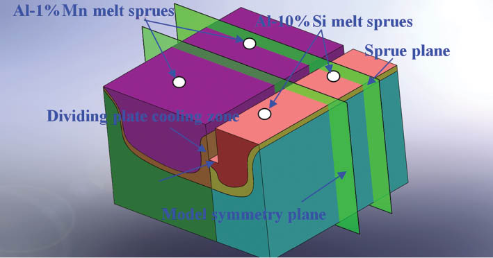
Diagram of model symmetry plane and sprue plane.
Specific boundary conditions:
1. Surface of the melt
The liquid melts were poured into the mold continuously, which can be seen as the Dirichlet problem. In the sprues of Al-1%Mn melt,
In the sprues of Al-10%Si melt,
where ρAl-1%Mn and ρAl-10%Si are the densities of Al-1%Mn and Al-10%Si melts, respectively. hAl-1%Mn and hAl-10%Si are the heights of the sprues to the melt surface, respectively; Tpour-Al-1%Mn and Tpour-Al-10%Si are the pouring temperatures of the Al-1%Mn and Al-10%Si melt, respectively. αAl-1%Mn and αAl-10%Si are the phase fractions of Al-1%Mn alloy and Al-10% alloy, respectively.
2. Water-cooled mold boundary
During the melt solidification, an air gap is formed between the mold and the shell. The heat transfer coefficient between the mold and the shell is assumed to vary with the solid fraction, which can be calculated as:
where hcontact is intended to reflect good thermal contact, hgap reflects a poor thermal contact when the gap is formed between the alloy and mold. fs is solid fraction, which is calculated as:
The secondary cooling boundary is divided into two zones: the air-cooling zone and the water-cooling zone. The coefficient of heat transfer in air cooling zone can be calculated as follows:
where σ is the Stefan-Boltzmann constant, ε is the blackness of the clad slab surface, and T is the surface temperature of the ingot.
After air-cooling zone, the ingot surface moves into the secondary water-cooling zone; the coefficient of heat transfer is given as follows:
where
3 Results and discussion
3.1 Simulation results
Figure 3 shows the influence of the casting speed on bimetal slab temperature field. It can be seen that the temperature decreases near the cooling zone and under the dividing plate. When the casting speed rises to 80 mm·min-1, the surface temperature of the solidification shell under the dividing plate is higher than that of 70 mm·min-1. It is because the raising of the casting speed shortens the time that the alloys have before they enter into contact.
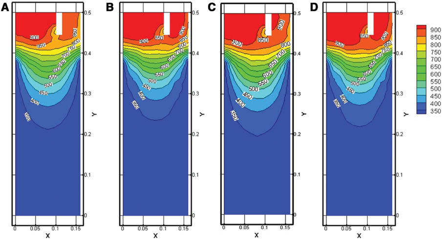
Influence of casting speed on the temperature field of clad slab: (A) symmetry plane, 70 mm·min-1; (B) sprues, 70 mm·min-1; (C) symmetry plane, 80 mm·min-1; (D) sprues, 80 mm·min-1.
Figure 4 shows the influence of casting speed on the liquid fraction of clad slab. It can be seen that the solidification shells at the sprue planes are thinner than those of symmetry planes under the same casting speed. The solidification shells maintain their shapes after they leave the bottom of the dividing plate at the casting speed of 70 mm·min-1, as shown in Figure 4A and B. The Al-1%Mn solidification shell becomes thinner when the casting speed rises to 80 mm·min-1. At the same time, the Al-1%Mn shell is remelted by the Al-10%Si melt, and the remelting is more obvious at sprue plane than that at symmetry plane, which is shown in Figure 4C and D. The temperature rises more easily with a thinner solidification shell, thus the liquid fraction rises. In the meantime, the melt cave at the casting speed of 80 mm·min-1 is deeper than that of the 70-mm·min-1 specimen. When the casting speed rises from 70 mm·min-1 to 80 mm·min-1, the thicknesses of the Al-1%Mn shell at the sprue and symmetry plane are reduced to 4 mm and 6 mm, respectively. The results indicate that the shell thickness at the symmetry plane is affected by the changing of the casting speed obviously. In that case, a lower casting speed can reduce the difference of the solidification shell at different positions.
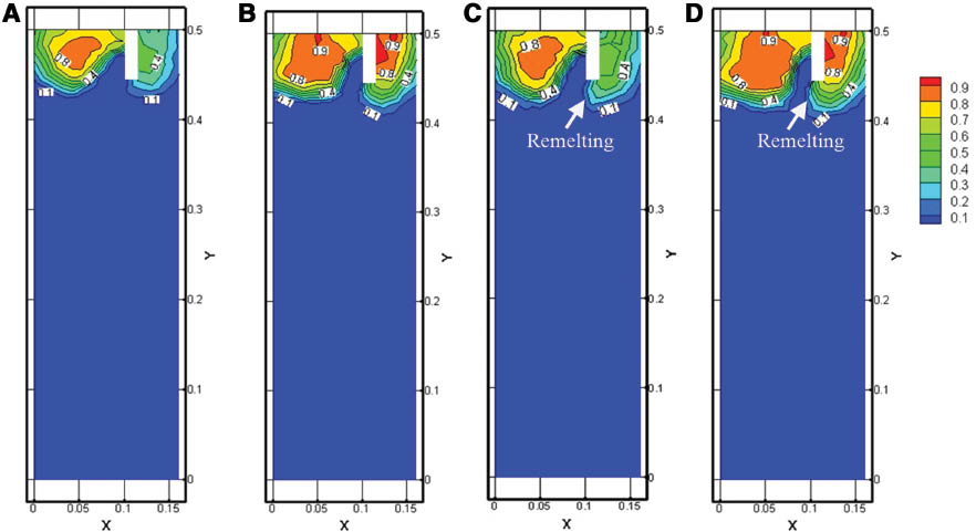
Influence of casting speed on the liquid fraction of clad slab: (A) symmetry plane, 70 mm·min-1; (B) sprues, 70 mm·min-1; (C) symmetry plane, 80 mm·min-1; (D) sprues, 80 mm·min-1.
3.2 Solidification structure
The cross-section macrostructure of the ingot at different casting speeds is shown in Figure 5. The interfaces of the clad slab are clear and straight. Two different Al alloys have no mixed flow in the interface as shown in the 70-mm·min-1 specimen. However, in the 80-mm·min-1 specimen, there is a small amount of mixed flows in the interface. But in the 80-mm·min-1 specimen, the Al-1%Mn melt flows into the Al-10%Si solidification shell from the cracks. In the meantime, the mixed flow does not expand into the further area after the whole cross-section solidified because the mixed interface can be restrained by secondary cooling.

Macrostructures of clad slab on cross section with different casting speed: (A) 70 mm·min-1 and (B) 80 mm·min-1.
Based on the simulation results, when the casting speed rises to 80 mm·min-1, the Al-1%Mn solidification shell gets thinner. When the thinner solidification shell leaves the cooling zone, the shell cannot support the Al-10%Si melt under the static pressure and dynamic pressure. The Al-10%Si melt strikes and remelts the low-strength solidification shell, resulting in the bending of the interface and some mixed flow through the cracks on the shell. Thus, it can be seen that the experimental and simulation results are reasonably consistent.
The microstructures of the clad slab at different casting speeds are shown in Figure 6. The Al-1%Mn solidification shell acts as the heterogeneous nucleation site of Al-10%Si alloy in the solidification process. The microstructure on the Al-1%Mn alloy side contains α-Al and (α-Al+MnAl6) eutectic phase while α-Al and (α-Al+Si) eutectic structure on the Al-10%Si alloy side. But the size of eutectic silicon in the 80-mm·min-1 specimen is smaller than that in the 70-mm·min-1 specimen. Because the raising of the casting speed brings the ingot to the secondary cooling area earlier, this results in the quick solidification of the Al-10%Si melt.
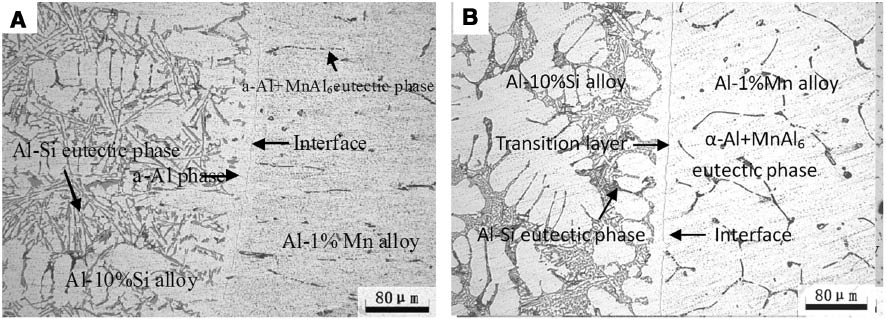
Microstructures of clad slab on cross-section with different casting speed: (A) 70 mm·min-1 and (B) 80 mm·min-1.
3.3 Composition distribution analysis
Figure 7 shows the composition distribution near the interface. It is clear to see a straight interface without melt mixture or serious remelting. The line scanning results indicate that the content of Si element decreases in the diffusion layer. The diffusion distance of Mn is much shorter than that of Si, which can be explained by two reasons.
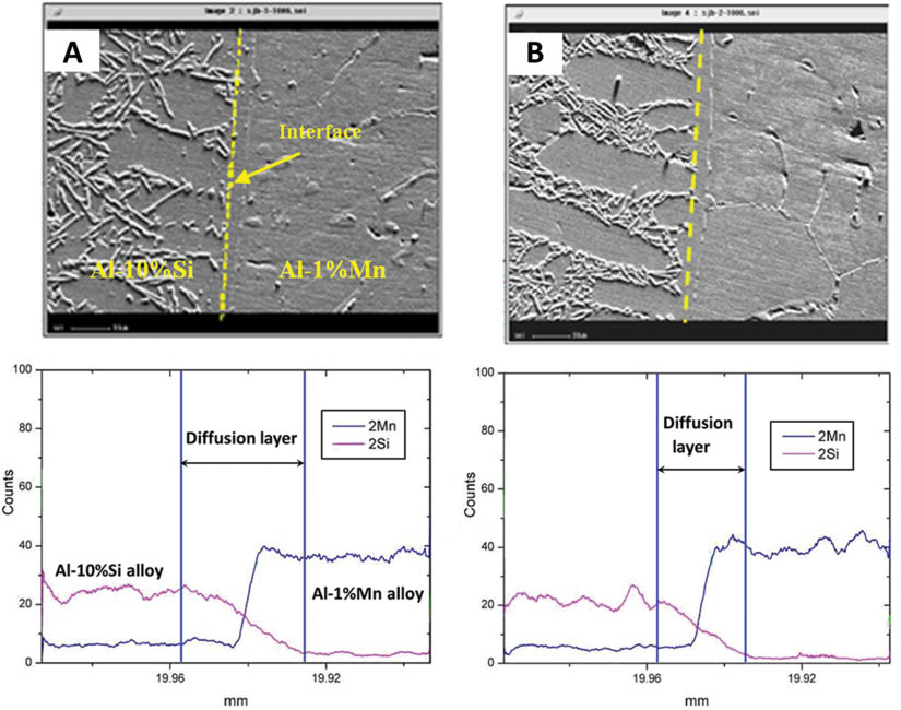
The content variations of Mn and Si at the diffusion layer of clad slab with different casting speeds: (A) 70 mm·min-1 and (B) 80 mm·min-1.
First, the diffusion coefficient is expressed by the Arrhenius equation:
where D0 is the diffusion constant and Q is the activation energy, T is absolute temperature, and R is the gas constant. The pre-exponential factor D0 and Q of Si and Mn are 3.5×10⁻⁵ m2·s-1, 120.5 kJ·mol-1 (617~904 K) and 2.2×10⁻⁵ m2·s-1, 123.9 kJ·mol-1 (723~923 K), respectively [18], [19]. The diffusion coefficient of Si into Al is calculated to be larger than that of Mn diffusion into Al in the temperature range of 723~904 K.
Second, the concentration gradient of the Mn element is lower than that of Si element in the diffusion layer. The diffusion layers are marked in Figure 7 based on the line analysis result of EPMA. The diffusion layer is formed by interdiffusion of Si and Mn in the Al matrix and is important for the mechanical properties of the interface.
In addition, from Figure 7, it can be seen that under different casting speeds, the diffusion distances are also different. The diffusion layer at 70 mm·min-1 is thicker than that at 80 mm·min-1. With the rise of the casting speed, the Al-1%Mn solidification shell is thinner. In the meantime, the temperature of the diffusion interface is higher than that of the lower casting speed specimen, which is beneficial to the elements diffusion. In that case, the diffusion layer of the higher casting speed specimen should be thicker than the lower casting speed one. However, the raising of the casting speed brings the diffusion area to the secondary cooling area earlier, resulting in the remarkable reduce of the element diffusion at the interface.
3.4 Mechanical properties
To examine the strength of the interface, a tensile test was carried out, and the specimens were taken from the same position of ingots gained by different casting speeds. The size of the tensile specimens is according to GB/T16865-1997 standard, which is equivalent to ASTM B557-1994 standard. The tensile specimens after tensile test are shown in Figure 8, and the tensile test results are shown in Table 3. It can clearly be seen that, with the raising of the casting speed, the mechanical properties do not change. From the EPMA results, there is an interdiffusion area near the interface. In this area, the elements Si and Mn diffuse into each other. Due to the solid solution strengthening effect, the strength of interface is higher than the Al-1%Mn alloy. The data on the tensile test can be seen as the lower limit value of the interface strength. Lloyd et al. found that the fracture of AA3003/AA6111 clad materials in tensile test always takes place in the lower strength AA3003 (Al-1Mn-0.5Fe-0.2Si); because plasticity predominantly occurs in the softer alloy, the failure occurs when the AA3003 reached its ultimate tensile strength [20]. These are consistent with the present study. The tensile test result indicates that a clad slab with an excellent metallurgical bonding in the interface can be obtained using the semi-continuous casting process.
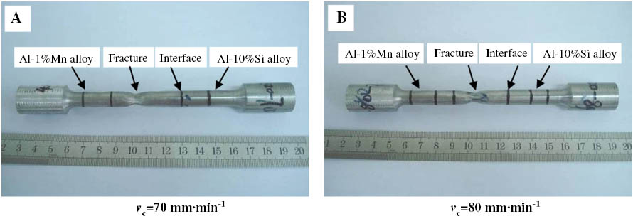
Tensile test results of clad slab under different casting speed: (A) 70 mm·min-1 and (B) 80 mm·min-1.
The tensile test data of clad slab under different casting speed.
| No. | Tensile speed (mm·min-1) | Tensile strength (MPa) | Elongation (%) |
|---|---|---|---|
| 1 | 70 | 107 | 26.5 |
| 2 | 80 | 103 | 20.9 |
4 Conclusions
The clad slab can be obtained when the Al-1%Mn alloy pouring temperature is 983 K, the pouring temperature of Al-10%Si alloy is 843 K, and the casing speed is 70–80 mm·min-1.
The analysis of the interface shows that the change of the casting speed does not influence the interface structure. When the casting speed rises to 80 mm·min-1, the eutectic silicon in the specimen is much smaller than in the 70-mm·min-1 specimens.
Elements distribution of Si and Mn is gradually variant. The Al-1%Mn alloy, which was poured into the mold earlier, serves as the substrate of heterogeneous nucleation of the Al-10%Si alloy. As a consequence, a diffusion layer is obtained between the Al-1%Mn and Al-10%Si alloy due to the solute diffusion. The greater casting speed reduces the diffusion time; in that case, the diffusion layer in 80-mm·min-1 specimen is thicker than that in the 70-mm·min-1 specimen.
The tensile strength of the clad specimen is about 100 MPa, and the fractured position is in the Al-1%Mn side, indicating that the interface strength is higher than the lower strength part of the material. The strength of the Al-1%Mn alloy is the lower limit value of the interface.
Acknowledgments
The authors wish to express their appreciation to the support of the National Natural Science Foundation of China (no. 51134013 and no. 51271042).
References
[1] Qwamizadeh M, Kadkhodaei M, Salimi M. ISIJ International 2013, 53, 265–273.10.2355/isijinternational.53.265Search in Google Scholar
[2] Paramsothy M, Srikanth N, Gupta M. J. Alloys Compd. 2008, 461, 200–208.10.1016/j.jallcom.2007.07.050Search in Google Scholar
[3] Wang Y, Zhang XG, Meng LG, Zhu H, Zhao M, Jiang N. J. Mater. Res. 2013, 28, 1601–1608.10.1557/jmr.2013.140Search in Google Scholar
[4] Song XY, Sun JB, Zhong DS, Yu YS, Wang TM, Cao ZQ, Li TJ. Mater. Res. Innovations 2012, 16, 51–55.10.1179/1433075X11Y.0000000012Search in Google Scholar
[5] Eizadjou M, Danesh MH, Janghorban K. Mater. Design 2008, 29, 909–913.10.1016/j.matdes.2007.03.020Search in Google Scholar
[6] Maleki H, Bagherzadeh S, Mollaei-Dariani B, Abrinia K. J. Mater. Eng. Perform. 2013, 22, 917–925.10.1007/s11665-012-0342-9Search in Google Scholar
[7] Lee JS, Son HT, Oh IH, Kang CS, Yun CH, Lim SC, Kwon HC. J. Mater. Process. Technol. 2007, 187, 653–656.10.1016/j.jmatprotec.2006.11.144Search in Google Scholar
[8] Zhang Y, Zeng X, Liu L, Lu C, Zhou H, Li Q, Zhu Y. Mater. Sci. Eng. A 2004, 373, 320–327.10.1016/j.msea.2004.02.007Search in Google Scholar
[9] Kaya Y, Kahraman N. Mater. Design 2013, 52, 367–372.10.1016/j.matdes.2013.05.033Search in Google Scholar
[10] Durgutlu A, Gülenç B, Findik F. Mater. Design 2005, 26, 497–507.10.1016/j.matdes.2004.07.021Search in Google Scholar
[11] Liu L, Wang H, Song G. J. Mater. Sci. 2007, 42, 565–572.10.1007/s10853-006-1068-6Search in Google Scholar
[12] Wang XH, Zhang M, Du BS. Mater. Manuf. Processes 2013, 25, 509–513.10.1080/10426914.2012.700154Search in Google Scholar
[13] Li N, Guo SR, Lu DX. J. Mater. Sci. Technol. 2002, 18, 187–188.10.1016/S0924-0136(02)00124-3Search in Google Scholar
[14] Zhang WW, Rohatgi PK, Shao M, Li YY. Mater. Sci. Eng. A 2009, 505, 120–130.10.1016/j.msea.2008.11.003Search in Google Scholar
[15] Jiang HX, Zhang HT, Qin K, Cui J-Z. Direct-chill semi-continuous casting process of three-layer composite ingot of 4045/3004/4045 aluminum alloys. Trans. Nonferr. Met. Soc. China 2011, 21, 1692–1697.10.1016/S1003-6326(11)60916-3Search in Google Scholar
[16] Gupta A, Lee ST, Wagstaff RB. Mater. Sci. Technol. 2007, 22, 71–75.10.1179/175355507X214069Search in Google Scholar
[17] Wang TM, Li J, Du YY, Yan ZM, Sun JB, Cai S, Xu JJ, Li TJ. Mater. Res. Innovations 2010, 14, 271–276.10.1179/143307510X12777574294786Search in Google Scholar
[18] Nagasaki S. Data Book of Metals, Japan Institute of Metals Press: Japan, 1993, p. 20.Search in Google Scholar
[19] Du Y, Chang Y, Huang B, Gong W, Jin Z, Xua H, Yuan Z. Mater. Sci. Eng. A 2003, 363, 140–151.10.1016/S0921-5093(03)00624-5Search in Google Scholar
[20] Lloyd DJ, Gallerneault M, Wagstaff RB. Metall. Mater. Trans. A 2010, 41, 2093–2103.10.1007/s11661-010-0298-zSearch in Google Scholar
©2017 Walter de Gruyter GmbH, Berlin/Boston
This article is distributed under the terms of the Creative Commons Attribution Non-Commercial License, which permits unrestricted non-commercial use, distribution, and reproduction in any medium, provided the original work is properly cited.
Articles in the same Issue
- Frontmatter
- Original articles
- Wave propagation in functionally graded piezoelectric-piezomagnetic rectangular bars
- Graphene/poly(vinylidene fluoride) dielectric composites with polydopamine as interface layers
- A novel biaxial double-negative metamaterial for electromagnetic rectangular cloaking operation
- Formation of homogenous copper film on MWCNTs by an efficient electroless deposition process
- Nano-SiCp/Al2014 composites with high strength and good ductility
- Microstrip line-fed monopole antenna on an epoxy-resin-reinforced woven-glass material for super wideband applications
- Influence of casting speed on fabricating Al-1%Mn and Al-10%Si alloy clad slab
- Thermal insulating epoxy composite coatings containing sepiolite/hollow glass microspheres as binary fillers: morphology, simulation and application
- Analysis of influence of fibre type and orientation on dynamic properties of polymer laminates for evaluation of their damping and self-heating
- Dynamic stability of nanocomposite viscoelastic cylindrical shells coating with a piezomagnetic layer conveying pulsating fluid flow
- Buckling and layer failure of composite laminated cylinders subjected to hydrostatic pressure
- One-step preparation and characterization of core-shell SiO2/Ag composite spheres by pulse plating
- The failure mechanism of carbon fiber-reinforced composites under longitudinal compression considering the interface
- A thermal-plastic model of friction stir welding in aluminum alloy
- A model for longitudinal tensile strength prediction of low braiding angle three-dimensional and four-directional composites
- Nonlinear stability of shear deformable eccentrically stiffened functionally graded plates on elastic foundations with temperature-dependent properties
- Design and multibody dynamics analyses of the novel force-bearing structures for variable configuration spacecraft

