A novel biaxial double-negative metamaterial for electromagnetic rectangular cloaking operation
-
 ,
,

Abstract
This paper presents the design and analysis of a novel biaxial double-negative (DNG) metamaterial for electromagnetic cloaking operation in the microwave range. The proposed metamaterial exhibits DNG characteristics for the three axes (x, y, and z axes) wave propagation through the material. For the z-axis wave propagation, it shows resonance in the X-band and shows DNG characteristics there. Similarly, for the x-axis wave propagation, the material displays resonances in the multi-band (S-, C-, and X-bands) microwave frequency ranges with DNG characteristics at the S-, C-, and X-bands. The material exhibits DNG properties at the S- and C-bands for y-axis wave propagation as well. In the basic design, a new metamaterial structure was developed that was split into two arms. The commercially available finite-difference time-domain (FDTD)-based computer simulation technology (CST) Microwave Studio software was adopted to obtain the reflection and transmission parameters of the unit cell. The metamaterial was then used in designing a rectangular electromagnetic cloaking device where a metal cylinder was perfectly cloaked in the C-band region of the microwave spectra. The metamaterial shows near-zero refractive-index property as well in the cloaked zone. This is a novel and promising design in the electromagnetic paradigm for its biaxial DNG characteristics and rectangular cloaking operation.
1 Introduction
In the recent years, a great deal of interest has been reported in the literature on the physics and engineering of metamaterial. Metamaterials are naturally unavailable artificially constructed uncommon materials that may have some exciting electromagnetic properties. These exotic properties may include negative permittivity (ε<0) or permeability (μ<0), negative refractive index, inverted Snell’s law, etc. Veselago in 1967 [1] depicted a concept of materials of such reversed characteristics, but the matter was not of much interest to researchers due to the unavailability of such natural materials. Around 30 years later, Smith et al. [2] in 2000 practically presented a composite material of such negative properties, and using such material, they successfully designed the first invisibility cloak in the microwave range in 2006 [3]. Metamaterial that displays both negative permittivity (ε) and negative permeability (μ) simultaneously is called double-negative (DNG) or left-handed (LH) metamaterial. Metamaterial with either negative permittivity or permeability is called single-negative (SNG) metamaterial. In this regard, according to Veselago, the sign of refractive index will be negative as well if both permittivity and permeability are found to be negative. However, because of these unconventional features of the metamaterial, it can be utilized in many important applications like electromagnetic absorption reduction, antenna design, filter design, invisibility cloaking, absorber design, etc. [3], [4], [5], [6], [7]. Many metamaterial structures have been proposed in the literatures for specific applications, but metamaterials with biaxial DNG properties are rarely found. For example, Turkmen et al. [8] presented a single-axial nested U-type metamaterial for C-and X-band applications, but they used multiple rings for producing multi-band functionality, and their metamaterial did not show DNG property. Dhouibi et al. [9] designed a z-shaped metamaterial for C-band applications, but their metamaterial was demonstrated for SNG property for one-axis wave propagation. In addition, currently, a metamaterial unit cell structure was reported in [10] for S-band applications, but it was showing epsilon negative property for the x-axis wave propagation only. Similarly, there are some DNG metamaterials found in the literature like Karamanos et al. [11] that proposed a dual-frequency single axial DNG metamaterial in C-band, but they used two different metamaterial structures in the two sides of the substrate. Islam et al. [12] claimed a DNG metamaterial for the z-axis wave propagation, but it was applicable only for C-band. Moreover, a multi-band DNG metamaterial was designed in [13], but it was displaying the DNG property for the x-axis wave propagation only. Recently, one of the prominent applications of metamaterial is invisibility cloak design. The cloak of invisibility is a form of technique that makes an object hidden. It was revealed earlier that, by reducing the scattering cross-section (SCS) from an object, cloaking could be performed at a specific frequency [14]. By using special metamaterial, this reduction of SCS can be achieved. Cloaking is usually done for military applications like concealment coating on missile or aircraft so that it cannot be tracked by the enemy. After the first design that was mentioned in [3], very few works are found in the literature in this field. For example, Alitalo et al. [14] designed a cylindrical cloak that works in 3.3 GHz. They also demonstrated a cloak in [15] for the X-band, but it was a cylindrical-type cloak. Wang et al. [16] constructed a cylindrical cloak as well using dielectric metamaterial, but it works only in the X-band.
In this paper, a new semi-pi-shaped biaxial metamaterial that shows DNG properties for x, y, and z-axis wave propagation in the microwave regime is proposed. Usually, a material can be characterized as “biaxial” if it has three different refractive indices corresponding to three principal coordinate axes of the material. The metamaterial is then used for designing a rectangular invisibility cloak that works in the C-band microwave spectra. Commercially available finite-difference time-domain (FDTD)-based simulation software was used to obtain the reflection and transmission parameters of the unit cell as well as the cloak.
2 Materials and methods
The design parameter and the schematic view of the proposed DNG unit cell structure are given in Figure 1(A). The unit cell structure is designed with two metal parts of copper, and they are placed in such a way that it forms a semi-pi-shape structure with all of them having thickness of 0.035 mm. Each part has two arms that are joined orthogonally. The two joined arms are not equal in size. There is a gap between the two parts, where the upside gap is denoted by “g”, and its value is 0.33 mm. Similarly, the lower side gap is denoted by “s”, and its value is 0.5 mm. To design a DNG metamaterial, the series branch of the unit cell circuit must contain an inductance or capacitance, and the corresponding shunt branch must contain the opposite order of reactance. In this design, each arm of the unit cell acts as inductance, and each gap of the unit cell is responsible for generating capacitance. The equivalent circuit is given in Figure 1(B). As the length of each arm and the gaps in the unit cell are not equal, the resistance, inductances, and capacitances are marked as R, L1, L2, C1, and C2, respectively.
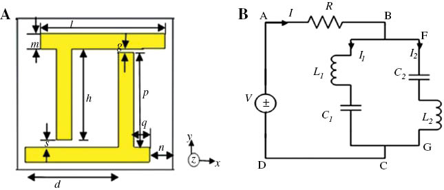
(A) The proposed unit cell structure and (B) equivalent circuit of the unit cell.
In the equivalent circuit, two loops were defined as ABCDA and BFGCB, and the current I (from the source) was divided into I1 and I2 at the junction B, where I=I1+I2(according to Kirchhoff’s 1st law). If, for the applied voltage V, the current produces Q charge in the capacitor, then from the loop ABCDA according to Kirchhoff’s 2nd law, the differential equation will be
Similarly, in the loop BFGCB,
Taking Laplace transformation in Equation 2,
After applying initial value theorem in Equation 4, the simplified equation will be
Similarly, from Equation 3, the simplified equation will be
Therefore, from Equations 5 and 6, the corresponding current and field calculation can be obtained.
However, the structure is designed over a square-shaped FR-4 substrate material with dielectric constant of 4.2 and dielectric loss tangent of 0.002. The side length and width of the substrate is 10 mm, and the thickness is 1.6 mm. The rest of the design parameters are seen in Table 1.
Design specification of the unit cell.
| Unit cell parameters | Value (mm) |
|---|---|
| d | 6 |
| g | 0.33 |
| h | 6 |
| l | 8 |
| m | 1 |
| n | 1.5 |
| p | 6.27 |
| q | 1 |
| s | 0.5 |
In this study, the commercially available FDTD-based computer simulation technology (CST) Microwave Studio software is used to obtain the transmission and reflection parameters of the unit cell. To show the biaxial operation of the unit cell, initially, the z-axis wave propagation is executed, and then the x- and y-axis wave propagations will be performed. For the z-axis wave operation, the unit cell was placed between positive and negative wave-guide ports at the z-axis, and the electromagnetic wave was propagated in the z-axis. The perfect electric and perfect magnetic conductor boundary conditions were applied in the rest of the axis. For simulation, frequency domain solver was used for simulation, and 1003 frequency samples were taken. The simulation was executed for frequency range between 1 and 15 GHz. The simulation geometry for z-axis wave propagation is seen in Figure 2(A).

(A) Simulation geometry for z-axis wave propagation, (B) fabricated prototype for measurement, and (C) current distribution of the unit cell at the frequency of 9.56 GHz.
For measurement purposes, a fabricated prototype was built using 14×23 unit cells, as seen in Figure 2(B). The dimension of the prototype was 140×230 mm2. The measurements were performed in a semi-anechoic chamber using two broadband horn antennas placed 1.5 m apart. The prototype was placed between the horn antennas in such a way that ensures z-axis wave propagation through the prototype. A vector network analyzer N5227A was used to calculate the reflection coefficient (S11) of the unit cell. Moreover, for calibration purposes, measurement with and without prototype was performed as well.
3 Results and discussion
The current distribution of the unit cell at the frequency of 9.56 GHz is shown in Figure 2(C). Unlike the split ring resonator, the current is following the opposite direction in the two arms of the unit cell because of the dissimilar geometry of the unit cell.
Figure 3(A) displays the S-parameters magnitude of the unit cell for the z-axis electromagnetic wave propagation. It depicts that the reflection parameter (R) has resonance at the frequency of 9.56 GHz that is in the X-band, and the transmission parameter (T) exhibits resonances in the frequencies of 8.46 and 12.67 GHz in the microwave. These resonances also belong to the X-band of the microwave spectra. However, the measured result is presented in Figure 3(B), where the measured S-parameters (S11and S21) are shown, and the reflection coefficient (S11) shows resonance at the same position (i.e. at the frequency of 9.56 GHz) of the simulated amplitude in Figure 3(A).
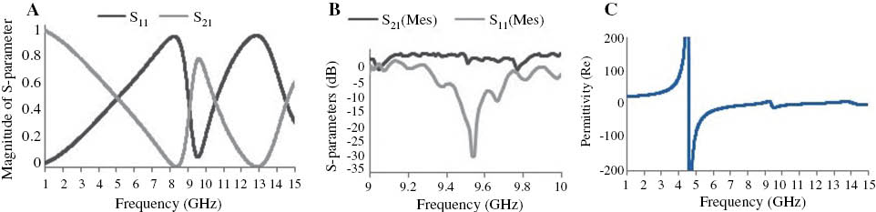
(A) Amplitude of S-parameters (reflection and transmission parameter) for the proposed unit cell structure, (B) measured S-parameters (S11and S21), and (C) real value of effective permittivity versus frequency for z-axis wave propagation.
The effective medium parameters permittivity, permeability, and refractive index can be determined from the simulated complex parameters S11(reflection coefficient) and S21(transmission coefficient) by the method mentioned in [17]. Figure 3(C) reveals the real magnitude of effective permittivity against frequency. The permittivity curve shows a negative magnitude at the frequency of 4.58 and 9.56 GHz. Figure 4(A) and (B) displays the real magnitude of effective permeability and the real value of the refractive index consecutively. It is seen from Figure 4(A) that the permeability curve has a clear negative magnitude from the frequency of 8.85 GHz, and it continues up to 11.33 GHz, including the resonance point at the frequency 9.56 GHz. It covers nearly 2.48-GHz frequency bandwidth in the microwave region. Usually, in the varying magnetic field, the gap between the arms of the unit cell forms charge density. Although, at low frequency, the current of the oscillator can remain in phase with the applied field, but at the higher frequency, it fails to cope. It then produces negative permeability at that frequency. Similarly, in Figure 4(B), it is evident that the refractive index (η) curve has a negative peak from the frequency of 9.38 to 11.33 GHz that covers almost 2-GHz frequency bandwidth in the X-band of the microwave spectra. However, it is notable here that the reflection parameter had a clear resonance at 9.56 GHz as well. Therefore, according to z-axis wave propagation, the material can be characterized as broadband DNG metamaterial for the X-band. Moreover, a near-zero refractive-index (NZRI) region is visible from the frequency of 5 to 8.48 GHz as well.

(A) Real value of effective permeability versus frequency and (B) real value of refractive index (η) versus frequency for z-axis wave propagation.
3.1 Results for the wave propagation in the x-axis
Further investigation was done by placing the metamaterial between the two positive, negative wave-guide ports at the x-axis to ensure x-axis wave propagation. The perfect electric and perfect magnetic conductor boundary conditions were applied in the rest of the axis. Figure 5(A) and (B) displays the simulation arrangement and the S-parameters magnitude of the unit cell for the z-axis wave propagation consecutively.

(A) Simulation geometry for x-axis wave propagation and (B) S-parameters (reflection and transmission coefficient) of the proposed unit cell structure for x-axis wave propagation.
In Figure 5(B), it is visible that, for the x-axis wave propagation, the reflection coefficient (S11) exhibits maximum resonances at the frequencies of 4.052, 7.412, and 10.52 GHz, which are in the range of S-, C-, and X-bands of the microwave spectra. Similarly, the transmission coefficient (S21) shows mentionable resonances at the frequencies of 4.86, 11.64, and 14.02 GHz that are in the range of C-, X-, and Ku-bands of the microwave spectra.
Figure 6(A) and (B) reveals the real curve of effective permittivity and permeability of the unit cell due to the x-axis wave propagation. The permittivity curve in Figure 6(A) displays a large range of negative magnitude from the frequency of 1.89 to 6.36 GHz. In addition, it also shows a negative value from 7.41 to 7.48, 10.02 to 10.62, and 11.57 to 13.64 GHz in the microwave region. Equally, in Figure 6(B), the effective permeability curve exhibits a negative peak from the frequency of 3.73 to 4.22, 5.73 to 7.62, 8.72 to 11.16, 12.97 to 13.22, and 13.82 to 15 GHz. Therefore, it is apparent that the material shows negative magnitude for both permittivity and permeability at the resonance points of 4.052, 7.412, and 10.52 GHz in the microwave spectra. Usually, the properties of permittivity and permeability are most likely affected by the polarization due to the internal architecture of the material. When electromagnetic waves enter in anisotropic materials, which have unequal lattice axes, it is affected by the polarization inside the material. As a result, the value of permittivity and permeability changes due to changes in the design. In the same way, the refractive index curve is also affected by the polarization.

(A) Real value of effective permittivity versus frequency and (B) real value of effective permeability versus frequency for the x-axis wave propagation.
However, the real magnitude of refractive index is seen in Figure 7 for x-axis wave propagation, where sharp resonances are seen in the S-, C-, and X-bands with value of refractive index η=-83.03, η=-24.56, and η=-11.40, respectively, at the frequencies of 3.73, 5.73, and 10.02 GHz of microwave spectra. In the S-band, the refractive index curve has negative magnitude from the frequencies of 3.73 to 4.22 GHz. In the C-band of the microwave spectra, it has a negative value from the frequencies of 5.73 to 6.31 GHz and from 7.41 to 7.48 GHz. Likewise, in the X-band, the refractive index curve reveals negative peak from the frequencies of 10.02 to 10.61 GHz. Consequently, it is clear that the material exhibits DNG property in the S-, C-, and X-bands of the microwave region for the x-axis wave propagation. However, it is remarkable that, after 1.8 GHz, in the rest of the places (except the negative region), the refractive index curve displays NZRI property that has potential applications in the high-gain antenna design.

Real value of refractive index (η) versus frequency for the x-axis wave propagation.
3.2 Results for the wave propagation in the y-axis
To ensure y-axis wave propagation through the metamaterial, the unit cell was placed between the two positive, negative wave-guide ports at the y-axis. The boundary conditions and same methodology were performed to obtain the value of the effective parameters. Figure 8(A) and (B) displays the simulation arrangement and the S-parameter magnitude of the unit cell for the y-axis wave propagation in a row.

(A) Simulation geometry for y-axis wave propagation and (B) S-parameters (reflection and transmission coefficient) of the proposed unit cell structure for y-axis wave propagation.
From Figure 8(B), it is visible that, for the y-axis wave propagation, the reflection coefficient exhibits major resonances (below -10 dB) at the frequencies of 3.25, 5.94, and 6.72 GHz that are in the range of S- and C-bands of the microwave spectra. Likewise, transmission coefficient displays stop band from the frequencies of 3.73 to 5.88 GHz in C-band and large stop band from the frequencies of 8.07 to 12.88 GHz that covers X-band and a few portions of Ku-band of the microwave spectra.
Figure 9(A) and (B) discloses the effective real magnitude of permittivity and permeability for the y-axis wave propagation through the unit cell. It is observable from Figure 9(A) that the permittivity curve has a sharp negative peak at the frequency of 1.95 GHz, and the negativity continues up to 5.80 GHz. It again shows a negative magnitude from the frequencies of 5.91 to 7.30 GHz. It also displays negativity from the frequencies of 12.73 to 13.81 GHz, and another sharp negative peak is visible in the frequency of 14.79 GHz in the microwave region. Similarly, in Figure 9(B), it is clearly seen that the permeability curve exhibits three resonances in the S-, C-, and X-bands of the microwave spectra. In the S-band, it shows a negative peak from the frequencies of 3.08 to 3.57 GHz. Equally, in the C-band, it displays negative magnitude from the frequencies of 5.67 to 6.78 GHz, and in the X-band, it reveals large negative bandwidth from the frequencies of 8.37 to 13.71 GHz in the microwave region. As a result, it is noticeable that according to the reflection parameter in Figure 8(B), the material shows negative permeability and permittivity at the frequency of 3.25 GHz in the S-band and 5.94 and 6.72 GHz in C-band of the microwave spectra. So, at these points of resonance frequency, the material can be characterized as DNG material.

(A) Real value of effective permittivity versus frequency and (B) real value of effective permeability versus frequency for the y-axis wave propagation.
Figure 10 depicts the real magnitude of the refractive index for the y-axis wave propagation of the unit cell. In Figure 10, it is visible that the refractive index curve shows mentionable negative peak in the S- and C-bands and a few portion of the Ku-band. In the S-band, it displays a sharp negative peak at the frequency of 3.10 GHz, and it continues exhibiting a negative value up to 3.57 GHz. In the C-band, the refractive index curve shows a negative magnitude from the frequencies of 5.67 to 5.80 and 5.91 to 6.78 GHz. Similarly, in the Ku-band, it exhibits a negative value from the frequencies of 12.73 to 13.71 GHz, which is nearly 1-GHz bandwidth. However, it is noticeable that two large portions in the refractive index graph are found exhibiting NZRI properties. One of those portions exists between the frequencies of 3.71 to 5.43 GHz, which is nearly 1.72-GHz bandwidth, and another from the frequencies of 8.51 to 12.46 GHz that cover almost the whole X-band portion in the microwave spectra. However, the value of refractive index (η) also satisfies the resonances that were found for the reflection coefficient at the frequencies of 3.25, 5.94, and 6.72 GHz with values of η=-33.88, η=-12.34, and η=-1.70, respectively. Additionally, according to the z-axis wave propagation, the negative refractive index resonance was at the frequency of 9.56 GHz with the value of ηz=-17.81. Similarly, at the same frequency for x-axis wave propagation, it was ηx =0.04, and for the y-axis wave propagation, it shows the near-zero value of ηy =0.11 that demonstrates the material biaxial properties.

Real value of refractive index (η) versus frequency for the y-axis wave propagation.
4 Design of an electromagnetic cloak using the metamaterial
In the further step, the material was then used to design an electromagnetic cloak. Cloak of invisibility is one kind of mechanism that makes a region of space or object to be hidden from view to the nearby observer. In case of electromagnetic cloak, the electromagnetic waves that strike upon it is guided in such a way that it will not be able to penetrate inside the cloaking space; rather, it will bend around the cloaking object. Scattering cancellation is one of the cloaking techniques where the object to be cloaked is surrounded by a kind of dielectric shell that will either cancel or reduce the scattering of the electromagnetic waves from the body of object. It causes the electromagnetic waves to return to its original path, and any object inside the cloak shell will not be seen by the outsider. To cloak an object, the SCS or normalized scattering width of a body has to be kept below one. Usually, natural material does not offer this opportunity easily. However, by employing metamaterial or by engineering the geometry of metamaterial, this task can be performed easily. In this study, a very simple single-layer rectangular cloak was designed.
The designed biaxial metamaterial was used to build the wall of the cloak. Four walls were built, and each wall was 400 mm2that was built by 2×2 unit cell. For simulation, the same methodology was used, and transverse electric wave was propagated through the cloak.
Figure 11(A) shows the simulation geometry of the cloak. From Figure 11(A), it is seen that a metallic (aluminium) cylinder has been placed in the cloak as an object to be concealed. The inner radius of the cylinder was 3 mm, and the outer radius was 4 mm. The metallic cylinder was placed in the middle of the cloak in such a way that the distance from the center of the cylinder to each of the metamaterial wall of the cloak was a=b=10 mm.

(A) Simulation geometry of the rectangular cloak with metal cylinder (inside) and (B) calculated result of normalized scattering width of cloaked object normalized to scattering width of bare object for the rectangular cloak.
Figure 11(B) reveals the calculated result of normalized scattering width of cloaked object normalized to scattering width of bare object for the rectangular cloak. It is seen that the normalized scattreing width curve shows below one value from the frequencies of 5.25 to 5.88 GHz, and the lowest value is achieved at 5.67 GHz. Therefore, the frequencies of 5.25 to 5.88 GHz are the regions where the object can be cloaked using the metamaterial shell.
In Figure 12(A) and (B), the numerical results of H-field distribution in the xy-plane at 5.67 GHz for both uncloaked and cloaked states are respectively shown. In Figure 12(A), the H-field distribution for the bare object (metal cylinder) is shown, where clear shadow or forward scattering is seen behind the object that indicated reflection in the backward direction. Therefore, if any person sees the object, staying in this shadow zone, he will be able to see the object. In Figure 12(B), the numerical results of H-field distribution in the xy-plane at 5.67 GHz for both cloaked objects are shown. It is evident from Figure 12(B) compared to Figure 12(A) that the forward scattering or shadow in the forward direction (behind the object) has been alleviated enough. It indicates that the plain wave has returned to its original path, and therefore the cloaking operation is performed. It is noted here that the cloaking operation achieved where the metamaterial shows NZRI property in all the three axes.

H-field distribution in the xy-plane at cloaked frequency (5.67 GHz) (A) for the bare object and (B) for the cloaked object.
5 Conclusions
In this study, a novel biaxial DNG metamaterial was presented. The metamaterial exhibits DNG properties for all the three principal axes (x, y, and z) wave propagation in the microwave regime. For characterization of the metamaterial, the FDTD-based simulation tool was utilized. The measured result agrees well with the simulated result as well. Later on, this metamaterial was used to design a rectangular cloak. It was shown that the proposed metamaterial-based rectangular cloak was able to cloak a cylindrical object in the C-band region of the microwave spectra where the metamaterial shows NZRI property. The design, simplicity, DNG characteristics, and rectangular cloaking operation have made the metamaterial novel in the electromagnetic paradigm.
References
[1] Veselago VG. Sov. Phys. Uspekhi 1968, 10, 509–514.10.1070/PU1968v010n04ABEH003699Search in Google Scholar
[2] Smith DR, Padilla WJ, Vier DC, Nemat-Nasser SC, Schultz S. Phys. Rev. Lett. 2000, 84, 4184–4187.10.1103/PhysRevLett.84.4184Search in Google Scholar PubMed
[3] Schurig D, Mock JJ, Justice BJ, Cummer SA, Pendry JB, Starr AF, Smith DR. Science 2006, 314, 977–980.10.1126/science.1133628Search in Google Scholar PubMed
[4] Faruque MRI, Islam MT, Misran N. Prog. Electromagn. Res. 2012, 124, 119–135.10.2528/PIER11112301Search in Google Scholar
[5] Ullah MH, Islam MT, Faruque MRI. Materials 2013, 6, 5058–5068.10.3390/ma6115058Search in Google Scholar PubMed PubMed Central
[6] Islam MT, Faruque MRI, Misran N. IEICE Electron. Express 2010, 7, 240–246.10.1587/elex.7.240Search in Google Scholar
[7] Shen X, Cui TJ, Zhao J, Ma HF, Jiang WX, Li H. Opt. Express 2011, 19, 9401–9407.10.1364/OE.19.009401Search in Google Scholar PubMed
[8] Turkmen O, Ekmekci E, Turhan-Sayan G. IET Microwaves Antennas Propag. 2012, 6, 1102–1108.10.1049/iet-map.2012.0037Search in Google Scholar
[9] Dhouibi A, Burokur SN, de Lustrac A, Priou A. Adv. Electromagnet. 2012, 1, 64–70.10.7716/aem.v1i2.82Search in Google Scholar
[10] Islam SS, Faruque MRI, Islam MT. J. Electr. Electron. Eng. 2014, 7, 13–16.10.3390/ma7074994Search in Google Scholar
[11] Karamanos TD, Dimitriadis AI, Kantartzis NV. IEEE Antennas Wirel. Propag. Lett. 2012, 11, 480–483.10.1109/LAWP.2012.2197170Search in Google Scholar
[12] Islam SS, Faruque MRI, Islam MT. Informacije MIDEM 2014, 44, 218–223.Search in Google Scholar
[13] Islam SS, Iqbal Faruque MR, Islam MT. Appl. Phys. A 2014, 116, 723–733.10.1007/s00339-014-8549-2Search in Google Scholar
[14] Alitalo P, Valagiannopoulos CA. Electron. Lett. 2012, 48, 1056–1057.10.1049/el.2012.2094Search in Google Scholar
[15] Alitalo P, Culhaoglu AE, Osipov AV, Thurner S, Kemptner E, Tretyakov SA. IEEE Trans. Antennas Propag. 2012, 60, 4963–4968.10.1109/TAP.2012.2207339Search in Google Scholar
[16] Wang X, Chen F, Semouchkina E. IEEE Microwave Wireless Compon. Lett. 2013, 23, 63–65.10.1109/LMWC.2013.2238914Search in Google Scholar
[17] Luukkonen O, Maslovski SI, Tretyakov SA. IEEE Antennas Wirel. Propag. Lett. 2011, 10, 3588–3596.10.1109/TAP.2011.2163750Search in Google Scholar
©2017 Walter de Gruyter GmbH, Berlin/Boston
This article is distributed under the terms of the Creative Commons Attribution Non-Commercial License, which permits unrestricted non-commercial use, distribution, and reproduction in any medium, provided the original work is properly cited.
Articles in the same Issue
- Frontmatter
- Original articles
- Wave propagation in functionally graded piezoelectric-piezomagnetic rectangular bars
- Graphene/poly(vinylidene fluoride) dielectric composites with polydopamine as interface layers
- A novel biaxial double-negative metamaterial for electromagnetic rectangular cloaking operation
- Formation of homogenous copper film on MWCNTs by an efficient electroless deposition process
- Nano-SiCp/Al2014 composites with high strength and good ductility
- Microstrip line-fed monopole antenna on an epoxy-resin-reinforced woven-glass material for super wideband applications
- Influence of casting speed on fabricating Al-1%Mn and Al-10%Si alloy clad slab
- Thermal insulating epoxy composite coatings containing sepiolite/hollow glass microspheres as binary fillers: morphology, simulation and application
- Analysis of influence of fibre type and orientation on dynamic properties of polymer laminates for evaluation of their damping and self-heating
- Dynamic stability of nanocomposite viscoelastic cylindrical shells coating with a piezomagnetic layer conveying pulsating fluid flow
- Buckling and layer failure of composite laminated cylinders subjected to hydrostatic pressure
- One-step preparation and characterization of core-shell SiO2/Ag composite spheres by pulse plating
- The failure mechanism of carbon fiber-reinforced composites under longitudinal compression considering the interface
- A thermal-plastic model of friction stir welding in aluminum alloy
- A model for longitudinal tensile strength prediction of low braiding angle three-dimensional and four-directional composites
- Nonlinear stability of shear deformable eccentrically stiffened functionally graded plates on elastic foundations with temperature-dependent properties
- Design and multibody dynamics analyses of the novel force-bearing structures for variable configuration spacecraft