The failure mechanism of carbon fiber-reinforced composites under longitudinal compression considering the interface
-
 ,
,

Abstract
In this paper, a longitudinal compression experiment of composites was conducted and the macroscopic failure mode was obtained. Also, the microscopic failure morphologies of longitudinal compression and kink band were observed by using scanning electron microscopy. It can be seen that, under compression, fibers bend and form a kink band, which is the most typical failure mode. Then a micromechanical model of fiber random distribution based on the random collision algorithm, which can reveal the progressive failure mechanism of longitudinal compression considering the kink-band deformation, was established, with two dominant damage mechanisms – plastic deformation and ductile damage initiation of the polymer matrix and interfacial debonding included in the simulation by the extended Drucker-Prager model and cohesive zone model, respectively. Through numerical simulation, the loading and failure procedures were divided into three stages: elastic domain, softening domain and fiber failure domain. It can be concluded that the kink band was a result of fiber instability (micro-bulking), which is caused by the elastic bending of fibers. The fibers rotate and break into two places, forming a kink band. Then the fibers rotate further until the matrix between the fibers fails and the kink-band breaks and, hence, the composite loses its load-bearing capability.
1 Introduction
Carbon fiber-reinforced composites are widely used for structural applications in aeronautics, astronautics and navigation. At the design stage, an efficient use of composites requires a complete understanding of their properties and failure mechanisms. In terms of composite bearing and failure, longitudinal compression is a typical loading state and it plays an important role in predicting the damage tolerance of structural components.
Rosen [1] proposed the first model for fiber-reinforced plastic failure under longitudinal compression, which is based on the in-phase micro-buckling of a two-dimensional layered (fibers and matrix) elastic material with no initial imperfection. It is recognized that the in-plane buckling of the fibers places the matrix pre-dominantly in shear. Argon [2] proposed that an initial local fiber misalignment would induce fiber bending and matrix shearing, forcing the material to rotate further in a positive feedback process and leading subsequently to ultimate failure during compression. After that, two approaches, micro-buckling and kinking, are most widely used to explain the essential mechanism of longitudinal compressive deformation and failure, which can be found in the references. Many other authors have also studied this failure mode.
Recent experimental investigations [3], [4], [5], [6], [7] have revealed that such laminates fail owing to the formation of a kink band; the fibers break at two points. This creates a band 10–15 fiber diameters wide inclined at a propagation angle of 5–15° to the horizontal axis, which is shown in Figure 1. Typical kink-band parameters such as the width (ω), the propagation angle (β) and the rotation angle (α) of the fibers are also shown in this figure. Failure by kink-band formation can be found in many other engineering materials such as non-crimp fabric [8], wood [9] and paper [10].
![Figure 1: The definition of a kink band. (A) Micrograph from experiment in Ref. [7]. (B) Schematics and definition of the kink-band geometric parameters: fiber angle α, band angle β, and band width ω.](/document/doi/10.1515/secm-2015-0057/asset/graphic/j_secm-2015-0057_fig_001.jpg)
The definition of a kink band. (A) Micrograph from experiment in Ref. [7]. (B) Schematics and definition of the kink-band geometric parameters: fiber angle α, band angle β, and band width ω.
Soutis and Fleck [5] tested carbon-epoxy unidirectional (UD) composites under uniaxial compression, using both unnotched and open-hole specimens. The main failure mode observed was fiber micro-buckling in the 0 ply. Vogler and Kyriakides [11] achieved a stable and almost in-plane propagation of kink bands in UD carbon fiber-reinforced polymers, using compression combined with shear. Pimenta et al. [12], [13] investigated the initiation and propagation of kink bands through an experimental study and numerical modeling. Based on the results achieved, the sequence of events and key features for kink-band formation were identified. Also, they developed an analytical micromechanical model for kink-band formation in a UD fiber-reinforced composite, which is based on the equilibrium of an imperfect fiber laterally supported by an elastic-plastic matrix. Gutkin et al. [14], [15], [16] investigated longitudinal compressive failure in notched UD and cross-ply carbon/epoxy specimens. They used a micromechanical finite element (FE) model to investigate the failure mechanisms and generate failure envelopes for fiber-reinforced composites under combined in-plane shear and longitudinal compressive loading. This was verified using an analytical model. Recently, Romanowicz [17] established a periodic unit cell model with non-uniform fiber waviness that is able to reproduce the mechanisms that govern the failure of fiber-reinforced polymers under compression and provide accurate characteristics of micro-buckling.
Although the aforementioned authors have done a lot of research on the failure mechanism of composites under longitudinal compression, an effective comparison between experiment and numerical simulation has not been given in detail. It is the same with specific sequence and mechanism of kink-band deformation. In this paper, a longitudinal compression experiment was conducted and the macroscopic failure mode was obtained. Also, the microscopic failure morphologies of longitudinal compression and kink band could be observed by using scanning electron microscopy (SEM). Then a micromechanical model of fiber random distribution based on the random collision algorithm, which can reveal the progressive damage process and failure mechanism of carbon fiber-reinforced composites under longitudinal compression considering the interface and the kink-band deformation, was established, with two dominant damage mechanisms – plastic deformation and ductile damage initiation of the polymer matrix and interfacial debonding included in the simulation by the extended Drucker-Prager model and cohesive zone model, respectively. The finite element method (FEM) analysis could reveal the mechanism of deformation and failure quantitatively.
2 Materials and methods
2.1 Specimen and preparation
The material system used in the experiment was CCF300/5228A (AVIC Beijing Institute of Aeronautical Materials, Beijing, China), and the longitudinal compression test was conducted according to ASTM D3410 [18]. The thickness of all specimens was taken as 2 mm, and the single layer thickness was 0.125 mm. The basic mechanical property testing of the composites was conducted on an Instron 5966 machine (Instron Corporation, Norwood, MA, USA). The load-displacement curve during the loading process was recorded through a data acquisition system, and the specimen strain in the test section was acquired through a strain gauge. The fracture surfaces of failed specimens were examined using SEM (JSM-5800, JEOL, Akishima, Tokyo, Japan), based on which the microscopic damage mechanism was determined.
2.2 Test result
The macroscopic loading conditions of the specimens are shown in Figure 2, and the microscopic failure morphologies are shown in Figure 3.

The macroscopic loading conditions of the specimens under longitudinal compression. (A) Before the test; (B) after the test.

The microscopic failure morphologies of the longitudinal compression. (A) At an amplification rate of 50 µm; (B) at an amplification rate of 10 µm.
The experiment results show that the failure mechanisms of longitudinal compression are quite complex. Simply stated, the longitudinal compressive properties are dominated by fiber properties because, in the experiment, after fiber breakage the composite completely loses its load-bearing capacity.
As shown in Figure 2, under compressive loading, the fibers bend and form a kink band. This is the most typical failure mode. In Figure 3, there obviously exist fiber breakage, matrix damage and kink band induced by bending, which all resulted from compression. The formation of a kink band leads to extensive interfacial debonding and matrix shear damage. The fibers then gradually lose peripheral support owing to the failure of the interface and the matrix. When the external load reaches a critical value, the fiber matrix completely debonds. Finally, the fibers break and a main crack throughout the cross section occurs.
3 Microscopic computational model
3.1 FEM model
This paper shows the development of a micromechanical model that can reveal the progressive damage process and failure mechanism of carbon fiber-reinforced composites under longitudinal compression considering the interface and the kink-band deformation. This model contains 25 fibers with 56% fiber volume fraction in consideration of both the validity of the model and the amount of calculation, based on the random collision algorithm. The model can capture the stress distribution, damage initiation and evolution more accurately and objectively. The size of the model is 1×1×17 mm, which is shown in Figure 4. Because the length of the model is far greater than the width, the stress distribution in the model is not influenced by the stress concentration at the loading end. The stress-strain responses of this model are similar to the experimental data, and the strength and ductility of different fiber distributions in a model that included 25 fibers remain stable on the whole. These ensure that the size of the model did not influence the model predictions significantly.

The micromechanical model.
The material system of the micromechanical model is CCF300/5228A, and the material properties of the fiber and the matrix used in the model are listed in Table 1. A 0.1-μm layer of cohesive elements defined in terms of the linear traction-separation law is inserted between the fiber and the surrounding matrix to simulate the interfacial mechanical behavior. Detailed information about the plastic matrix and the cohesive element is shown in Section 3.2.
The material properties of CCF300/5228A [19].
| Fiber/CCF300 | |
|---|---|
| Longitudinal modulus, E1f (GPa) | 224.29 |
| Transverse modulus, E2f=E3f (GPa) | 30.18 |
| The in-plane shear modulus, G12f=G13f (GPa) | 70.64 |
| The in-plane Poisson’s ratio, ν12f=ν13f | 0.243 |
| Transverse shear modulus, G23f (GPa) | 11.52 |
| Transverse Poisson’s ratio, ν23f | 0.310 |
| Matrix/5228A | |
| Modulus, Em (GPa) | 3.22 |
| Poisson’s ratio, νm | 0.346 |
In the longitudinal compression model, the fiber is the main load-bearing constituent. In order to simulate the mechanical behavior of micro-bulking, the initial fiber misalignment is defined in the FEM model to represent the fiber imperfection. When the stress transferred from the matrix exceeds the strength of the fiber, the fiber will break and lose its bearing capacity in the axial direction. The maximum stress criterion adopted for the fiber is given as follows:
where Xt and Xc are the tensile and compressive strength of the fiber in the axial direction, respectively.
The Young’s modulus of the fiber is reduced after the failure criterion is satisfied, as expressed in the following equation:
For the CCF300 carbon fiber, Xt=3500 MPa and Xc=2290 MPa [19]. Ef is the elastic modulus of the fiber without damage,
The free boundary condition is as follows according to Ref. [12]: one boundary surface of the micromechanical model, which is perpendicular to the fiber direction, is clamped, and the displacement load along the fiber axis is imposed on the other free boundary surface until the micromechanical model becomes damaged and fails.
The fibers and the matrix were meshed with eight-node linear brick reduced integration elements (C3D8R) with an hourglass control, and the interface was meshed with eight-node three-dimensional cohesive elements (COH3D8).
3.2 Plastic matrix and the interface cohesive zone
In order to effectively simulate the effect of the yield behavior of the matrix plastic on the kink-band formation under longitudinal compressive loading, this paper used the extended linear Drucker-Prager criterion to predict the yield of the polymeric matrix, which includes the effect of hydrostatic stress on yield behavior [20]. This can be expressed in Equation 2.
where p is the hydrostatic stress, q is the von Mises equivalent stress, r is the third invariant of deviatoric stress, β(θ, fi) is the slope of the linear yield surface in the p-t stress plane and is commonly referred to as the friction angle of the material, d is the cohesion of the material and K(θ, fi) is the ratio of the yield stress in triaxial tension to the yield stress in triaxial compression.
Ductile criterion is used to predict the damage initiation discriminating between the different triaxial stress states. After the initiation of failure, the damage evolution is controlled by a progressive failure procedure, which is illustrated in Figure 5A. The dashed curve in the figure is the stress–strain response in the absence of damage, while the solid curve represents the damaged response. The damage manifests itself in two forms: softening of the yield stress and degradation of the elasticity, both of which are related to the damage variable D.

(A) Stress-strain behavior of the polymeric matrix. (B) Traction-separation law of the cohesive element.
In the figure, σy0 and
According to Refs. [21], [22], for most epoxy matrixes, the parameters of the Mohr-Coulomb model are φ=15° and c=39.1 MPa, which make the tensile and compressive strength to be σt=60 MPa and σc=101.9 MPa, respectively. According to Ref. [20], these parameters can be converted to the parameters of the extended linear Drucker-Prager model by Equation 3:
The implementation of this stress-displacement concept in a finite element model requires the definition of a characteristic length (L) that is associated with an integration point. The fracture energy is then given as
The material parameters of the matrix are shown in Table 2. And the equivalent plastic strains at the initiation of damage for uniaxial tension and compression are set to 0.05 and 0.5, respectively [21], [22].
Material parameters of the matrix.
| d (MPa) | B | k | Gm (J/m2) |
|---|---|---|---|
| 64.7 | 24° | 0.8 | 0.5 |
The interface in this paper uses a cohesive element defined in terms of the linear traction-separation law, which relates the separation displacement between the top and the bottom faces of the element to the traction vector acting upon it.
The nominal traction stress vector, t, consists of three components: tn, ts and tt, which represent the normal and two shear tractions, respectively.
In an elastic-linear softening constitutive model, the traction stress vector is defined as follows:
where Kii (i=n, s, t) is the stiffness coefficient corresponding to the three stresses in the cohesive element and εi (i=n, s, t) is the three strains.
The corresponding separations are denoted by δn, δs and δt. Let T0 denote the original thickness of the cohesive element. The nominal strains can be defined as
The stress-strain relationship of the cohesive element after the fraction is shown in Figure 5B. The traction stress is reduced depending on the interface damage parameter D, which evolves from 0 (in the absence of damage) to 1 (at ultimate failure). The displacement at failure is determined by the fracture energy G, which corresponds to the area under the traction-separation curve.
A quadratic nominal stress criterion is used to simulate the initial damage, which can be represented as
where
The power law criterion states that failure under mixed-mode conditions is governed by a power law interaction of the energies required to cause failure in the individual (normal and two shear directions) mode. It is given by
where
The values of the interfacial parameters are taken from Refs. [21], [22], which are shown in Table 3.
Material parameters of the interface.
| Kn=Ks=Kt (GPa/m) | Gn=Gs=Gt (J/m2) | |
|---|---|---|
| 108 | 39.1 | 100 |
4 Results and discussion
Through numerical simulations, the average stress-strain response and the progressive damage process of longitudinal compression can be obtained. The stress-strain curves of the micromechanical model and the macroscopic experiment under longitudinal compressive loading are shown in Figure 6. The loading and failure procedure can be evidently divided into three stages: elastic domain, softening domain and fiber failure domain. The micromechanical simulation and the macroscopic experiment results can meet well with each other. Contrary to the experimental stress-strain curve, the predicted curve is not smooth. Because ABAQUS/Explicit was used to conduct the quasi-static problem, the fluctuation in the elastic region of the predicted stress-strain curve was induced by the inertia force. After the stress-strain curve reaches the failure region, successive failure occurs in the composite constituents (fiber, matrix and interface) and cracks grow and cross-link in the model. Very violent fluctuations occur in the predicted stress-strain curve. The experimental stress-strain curve was obtained by linking the stress-strain points, which were acquired through a testing machine and a strain gauge, and it was obtained after treatment (through the numerical fitting of the load-time curve and the strain-time curve). So, the experimental stress-strain curve appeared smoother than the predicted stress-strain curve.

The stress-strain curves of the micromechanical model and the macroscopic experiment under longitudinal compressive loading.
Through combining the characteristic points on the stress-strain curve with the corresponding damage states in analysis, the damage initiation and evolution process of the fiber-reinforced composite under a particular load and the sequence of events for the kink-band formation can be proposed. When the stress-strain curve is before point A, it is the elastic domain (Figure 7A, F and K), and the fibers and the matrix deform elastically. The initial imperfection of fiber misalignment induces a slight bending of the fibers and shears the matrix. When the stress-strain curve reaches point B, it is the primary stage of the softening domain, and the initial interface debonding and matrix cracking occur (Figure 7B, G and L). As compression continues (point C), the interface debonding further expands (Figure 7C) and the matrix yields in shear within an inclined band developed across all the layers along the full model width (Figure 7H). The limited support given there to the fibers promotes deflection in a kinked where fibers bend at two points and a band region between them comes into being gradually (Figure 7M), with highly curved and stressed regions near the yield band boundaries. The overall stiffness drops suddenly. In the FEM results, owing to the use of numerical stabilization and to the edge effect, the peak load was artificially increased and the transition between the elastic and the softening domains was smooth. As the stress-strain curve reaches point D, it is the peak load of the compression process, the interface completely debonds (Figure 7D) and the matrix damages at each position form the main cracks (Figure 7I). Fiber rotation increases locally within a widening yield band. Axial fiber bending stresses increase within the maximum bending bands (Figure 7N) at its boundaries. Point E represents fiber failure domain. As the fiber curvature increases in the maximum bending bands, their strength is reached and the initial failure occurs at the outer fibers; as the damage propagates inwards, the location and orientation of the yield and the maximum bending bands stabilize, and only fiber rotation increases until the final fiber breaks and the kink-band geometry is fully formed (Figure 7E, J and O).

The deformation and progressive damage process of carbon fiber-reinforced composites under longitudinal compression.
(A) Interfacial initial debonding at longitudinal compressive strain load ε=0.55%. (B) Interfacial debonding at longitudinal compressive strain load ε=0.69%. (C) Interfacial debonding at longitudinal compressive strain load ε=0.82%. (D) Interfacial debonding at longitudinal compressive strain load ε=0.95%. (E) Interfacial debonding at longitudinal compressive strain load ε=1.00%. (F) Matrix damage at longitudinal compressive strain load ε=0.55%. (G) Matrix initial damage at longitudinal compressive strain load ε=0.69%. (H) Matrix damage at longitudinal compressive strain load ε=0.82%. (I) Matrix damage at longitudinal compressive strain load ε=0.95%. (J) Matrix damage at longitudinal compressive strain load ε=1.00%. (K) Fiber micro-bulking and stress distribution at longitudinal compressive strain load ε=0.55%. (L) Fiber micro-bulking and stress distribution at longitudinal compressive strain load ε=0.69%. (M) Fiber micro-bulking and stress distribution at longitudinal compressive strain load ε=0.82%. (N) Fiber micro-bulking and stress distribution at longitudinal compressive strain load ε=0.95%. (O) Fiber micro-bulking and stress distribution at longitudinal compressive strain load ε=1.00%.
Figure 8 shows a fairly standard kink band obtained by numerical simulation wherein all the relevant parameters can be effectively defined. ω is the band width, α represents the fiber angle and β is the band angle. This is a typical microscopic unit in actual failure mode. During the kink-band formation, the material constituent damage can be obviously observed, including the interfacial debonding, matrix cracking and fiber micro-bulking. Previously, some researchers [2] considered kinking to be independent from micro-buckling, and they thought that kink band was based on matrix yielding or cracking owing to the initial fiber misalignments and on further phase-shifted rotation owing to the loading. But in our FEM analysis, quite apparent fiber micro-bulking can be gained. During matrix yielding, the fiber gradually loses peripheral support. So it bends to one side owing to the initial imperfection, and this is the phenomenological conclusion. Based on FEM analysis, this phenomenological conclusion is a result of fiber instability (micro-bulking). Micro-buckling in composites is thought to be caused by the elastic bending of fibers, which is induced by misalignments and loaded by resin matrix material in shear. The fibers rotate and break into two places, forming a kink band. The fibers then rotate further until the matrix between the fibers fails, and the kink-band breaks and, hence, the composite loses its load-bearing capability. So, fiber instability and initial misalignments will both have an effect on the failure behavior under longitudinal compression.
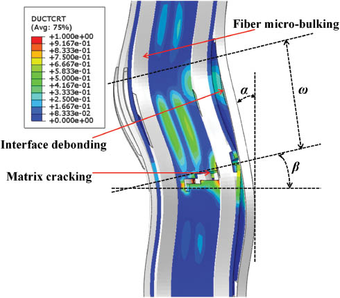
The deformation and damage propagation during the kink-band formation.
This micromechanical model has aided the design and safe applications of new material constituent matching by predicting the performance of the engineering composite materials. Also, it can be useful in implementing the concept of material design. A particular kind of composite material with optimal performance in order to meet its working requirements can be gained by adjusting the parameters of the mechanical property and their matching of composite constituents through this micromechanical model, so as to provide a theoretical basis for the optimal design and development of composites.
For multi-directional engineering composites, a more complex model whose mechanical properties (stiffness, strength, roughness) are much closer to real engineering composites should be established. The simplest multi-directional composite is the quasi isotropic laminates ([45/0/-45/90]4s). In the future, the numerical simulation of quasi isotropic laminates based on the existing modeling of UD composites will be conducted.
5 Conclusions
Experimental testing and numerical simulation are the most commonly used methods for studying the deformation and failure behavior of composites. In this paper, a longitudinal compressive experiment was conducted. It was concluded that the longitudinal compression properties are dominated by the fiber properties, and under compressive loading the fibers bend and form a kink band, which is the most typical failure mode. Through SEM, it can be seen that the formation of a kink band leads to extensive interfacial debonding and matrix shear damage. Fibers gradually lose peripheral support owing to the failure of the interface and the matrix. Finally, the fibers break and the composite loses its load-bearing capability.
Through FEM analysis, a micromechanical model that can reveal the progressive damage process and failure mechanism of carbon fiber-reinforced composites under longitudinal compression considering the interface and the kink-band deformation was established, and the loading and failure procedure can be evidently divided into three stages: elastic domain, softening domain and fiber failure domain. The detailed damage initiation and evolution process of fiber-reinforced composite constituents under compression and the sequence of events for kink-band formation were also proposed. During kink-band formation, the material constituent damage can be obviously observed. First, the fibers and the matrix deform elastically. Then, the initial imperfection of fiber misalignment induces a slight bending of the fibers and shears of the matrix and then the initial interface debonding and matrix cracking occur. As compression continues, the interface debonding further expands, and the matrix yields in shear within an inclined band developed across all the layers along the full model width. The limited support given there to the fibers promotes deflection in a kinked where fibers bend at two points and a band region between them comes into being gradually, with highly curved and stressed regions near the yield band boundaries. The overall stiffness drops suddenly. As fiber curvature increases in the maximum bending bands, their strength is reached and initial failure occurs at the outer fibers; as the damage propagates inwards, the location and orientation of the yield and the maximum bending of the bands stabilize, and only fiber rotation increases until the final fiber breaks and the kink-band geometry is fully formed, with a large amount of matrix cracking.
It also can be concluded that the kink band is a result of fiber instability (micro-bulking), which is thought to be caused by the elastic bending of fibers, and loaded by the resin matrix material in shear. The fibers rotate and break into two places, forming a kink band. The fibers then rotate further until the matrix between the fibers fails and the kink-band breaks and, hence, the composite loses its load-bearing capability. So, fiber instability and initial misalignments will both have significant effects on the failure behavior under longitudinal compression.
Acknowledgments
The financial support of the National Basic Research Program (973) of China (under grant no. 2010CB631103) is acknowledged.
References
[1] Rosen VW. Mechanics of Composite Strengthening. Fibre Composite Materials, American Society of Materials: Metals Park, OH, 1965.Search in Google Scholar
[2] Argon AS. Fracture of Composites. Treatise on Materials Science and Technology, Academy Press: New York, 1972.10.1016/B978-0-12-341801-2.50007-2Search in Google Scholar
[3] Soutis C. ASTM STP 1997, 1242, 168–176.10.1520/STP18275SSearch in Google Scholar
[4] Guynn EG, Bradley WL, Ochoa O. J. Compos. Mater. 1992, 26, 1594–1627.10.1177/002199839202601103Search in Google Scholar
[5] Soutis C, Fleck NA. J. Compos. Mater. 1990, 24, 536–558.10.1177/002199839002400505Search in Google Scholar
[6] Moran P, Liu L, Shih C. Acta Metall. Mater. 1995, 43, 2943–2958.10.1016/0956-7151(95)00001-CSearch in Google Scholar
[7] Pinho ST, Robinson P, Iannucci L. Compos. Sci. Technol. 2006, 66, 2069–2079.10.1016/j.compscitech.2005.12.023Search in Google Scholar
[8] Edgren F, Asp LE, Joffe R. Compos. Sci. Technol. 2006, 66, 2865–2877.10.1016/j.compscitech.2006.02.021Search in Google Scholar
[9] Benabou L. Mech. Mater. 2010, 42, 335–343.10.1016/j.mechmat.2009.11.015Search in Google Scholar
[10] Wadee MA, Hunt GW, Peletier MA. J. Mech. Phys. Solids. 2004, 52, 1071–1091.10.1016/j.jmps.2003.09.026Search in Google Scholar
[11] Vogler TJ, Kyriakides S. Int. J. Solids. Struct. 2001, 38, 2639–2651.10.1016/S0020-7683(00)00174-8Search in Google Scholar
[12] Pimenta S, Gutkin R, Pinho ST, Robinson P. Compos. Sci. Technol. 2009, 69, 948–955.10.1016/j.compscitech.2009.02.010Search in Google Scholar
[13] Pimenta S, Gutkin R, Pinho ST, Robinson P. Compos. Sci. Technol. 2009, 69, 956–964.10.1016/j.compscitech.2009.02.003Search in Google Scholar
[14] Gutkin R, Pinho ST, Robinson P, Curtis PT. Compos. Sci. Technol. 2010, 70, 1223–1231.10.1016/j.compscitech.2010.03.010Search in Google Scholar
[15] Gutkin R, Pinho ST, Robinson P, Curtis PT. Compos. Sci. Technol. 2010, 70, 1214–1220.10.1016/j.compscitech.2010.03.009Search in Google Scholar
[16] Gutkin R, Pinho ST, Robinson P, Curtis PT. Mech. Mater. 2011, 43, 730–739.10.1016/j.mechmat.2011.08.002Search in Google Scholar
[17] Romanowicz M. J. Compos. Mater. 2014, 48, 2387–2399.10.1177/0021998313498106Search in Google Scholar
[18] ASTM D3410/D3410M-03, Standard Test Method for Compressive Properties of Polymer Matrix Composite Materials with Unsupported Gage Section by Shear Loading, ASTM International: West Conshohocken, PA, USA, 2003.Search in Google Scholar
[19] Li X. Research on Multi-Scale Failure Analysis Method and Typical Laminates’ Failure Law of Composite Materials, Beihang University: Beijing, 2014.Search in Google Scholar
[20] ABAQUS theory manual. Abaqus 6.11 Documentation. HKS Inc.: Providence, RI, USA, 2011.Search in Google Scholar
[21] Yang L, Yan Y, Liu Y, Ran Z. Compos. Sci. Technol. 2012, 72, 1818–1825.10.1016/j.compscitech.2012.08.001Search in Google Scholar
[22] Gonzalez C, LLorca J. Compos. Sci. Technol. 2007, 67, 2795–2806.10.1016/j.compscitech.2007.02.001Search in Google Scholar
©2017 Walter de Gruyter GmbH, Berlin/Boston
This article is distributed under the terms of the Creative Commons Attribution Non-Commercial License, which permits unrestricted non-commercial use, distribution, and reproduction in any medium, provided the original work is properly cited.
Articles in the same Issue
- Frontmatter
- Original articles
- Wave propagation in functionally graded piezoelectric-piezomagnetic rectangular bars
- Graphene/poly(vinylidene fluoride) dielectric composites with polydopamine as interface layers
- A novel biaxial double-negative metamaterial for electromagnetic rectangular cloaking operation
- Formation of homogenous copper film on MWCNTs by an efficient electroless deposition process
- Nano-SiCp/Al2014 composites with high strength and good ductility
- Microstrip line-fed monopole antenna on an epoxy-resin-reinforced woven-glass material for super wideband applications
- Influence of casting speed on fabricating Al-1%Mn and Al-10%Si alloy clad slab
- Thermal insulating epoxy composite coatings containing sepiolite/hollow glass microspheres as binary fillers: morphology, simulation and application
- Analysis of influence of fibre type and orientation on dynamic properties of polymer laminates for evaluation of their damping and self-heating
- Dynamic stability of nanocomposite viscoelastic cylindrical shells coating with a piezomagnetic layer conveying pulsating fluid flow
- Buckling and layer failure of composite laminated cylinders subjected to hydrostatic pressure
- One-step preparation and characterization of core-shell SiO2/Ag composite spheres by pulse plating
- The failure mechanism of carbon fiber-reinforced composites under longitudinal compression considering the interface
- A thermal-plastic model of friction stir welding in aluminum alloy
- A model for longitudinal tensile strength prediction of low braiding angle three-dimensional and four-directional composites
- Nonlinear stability of shear deformable eccentrically stiffened functionally graded plates on elastic foundations with temperature-dependent properties
- Design and multibody dynamics analyses of the novel force-bearing structures for variable configuration spacecraft