Enhancing the machining productivity in PMEDM for titanium alloy with low-frequency vibrations associated with the workpiece
-
Dung Le Quang
 and
Muthuramalingam Thangaraj
and
Muthuramalingam Thangaraj

Abstract
The incorporation of frequency vibration into the powder mixed electric discharge machining (PMEDM) process has the potential to significantly enhance the productivity and quality of the machining process, as well as to provide a great deal of opportunities in this sector. An analysis and evaluation of the machining productivity (material removal rate [MRR]) in PMEDM with low-frequency vibration was carried out in this work by considering SKD61 as a workpiece. The oil dielectric solution mixed with titanium powder was used as a dielectric medium with red copper (Cu) as the electrode. At this point in time, the process technology parameters that have been chosen for inquiry are as follows: current (I), pulse on time (T on), powder concentration (C p), P, F, and A. The Taguchi technique (L25) was used to create the experimental matrix. With the use of analysis of variance, it was able to examine the impact that the factors had on MRR, and the analysis was utilized to ascertain the highest possible value of MRR. I was the parameter that has the most significant effect, according to the findings, whereas T on was the parameter that has the least significant effect. The maximum value of the MRRmax is equal to 31.29 mm3/min.
1 Introduction
Electric discharge machining (EDM) is still the needed technique when it comes to the area of machining complicated three-dimensional surfaces, in comparison to other non-traditional ways of machining. On the other hand, the necessity that leads to the application of EDM in practice is the restriction that this technique has in terms of productivity and the quality of the machined surface. At this time, powder-mixed EDM (PMEDM) has been utilized with dielectric fluid solution mingled with powder particles that have the potential to overcome these restrictions. The efficacy of this solution in boosting both productivity and the quality of the machined surface is rather substantial [1]. PMEDM is a solution that has a great deal of promise for the future. PMEDM does, however, have a few drawbacks, including the fact that powder particles in the dielectric fluid are not uniform, the presence of powder particles in the discharge gap, and the fact that the process of attracting and repelling the dielectric fluid using powder is quite difficult. Experts in this industry are paying attention to this matter since it is a problem that is catching their notice. Multiple investigations have shown that the combination of conductive powder and dielectric fluid is a successful method for achieving the desired results. As the concentration of chromium powder in PMEDM increases from 2 to 6 g/l, the quality metrics are significantly impacted. Specifically, the metal removal rate (MRR) increases while the TWR decreases as the powder concentration increases [1]. There is a significant difference in the efficacy of Gr powder in PMEDM and that of H3BO3 powder. Additionally, the surface roughness (SR), MRR, and tool wear rate (TWR) indicators are improved when graphite (Gr) powder is used [2]. There is a direct correlation between the rise in powder concentration and the decrease in SR, as well as the increase in MRR, TWR, and the micro-hardness of the surface area. Aluminum (Al) powder that was combined with dielectric fluid resulted in a rise in MRR, a reduction in TWR, and a reduced SR [3,4,5]. There is a substantial relationship between MRR and the technical parameters of silicon powder concentration and current intensity in PMEDM [6]. Using Gr powder, it was shown that the TWR of heat-treated copper was lower than that of copper in the PMEDM investigation [7]. Taking into account the contributions of Gr powder, SiC powder, and Al2O3 powder in PMEDM, it was discovered that Gr powder would result in the highest MRR, while SiC powder will result in the lowest TWR [8]. Increasing the amount of SiC powder that was present in the dielectric fluid led to a 90% increase in the MRR [9]. The PMEDM approach has been shown to have a great deal of potential in terms of enhancing both production and quality, according to literatures. The efficacy of low-frequency vibration used in PMEDM has been investigated in a number of research works, and the study of integrated vibration in EDM and PMEDM has been presented in a number of studies as well. The use of PMEDM in conjunction with vibration helped to further enhance the equal distribution of powder particles inside the discharge gap, which ultimately resulted in improved spark generation. A further point to consider is that the constant movement of the workpiece or electrode in an upward and downward direction could result in an increase in pressure, which will force the chip particles out of the discharge gap [10]. As a result, the discharge process becomes more steady, which in turn leads to an increase in the effectiveness of EDM machining. The integrated vibration in PMEDM that makes use of Gr powder has led to a reduction in the amount of time required for machining that is three times shorter [11]. Low-frequency vibration applied to the workpiece in PMEDM utilizing titanium powder results in increased efficiency [12]. This is in contrast to EDM, which uses high-frequency vibration. When compared to EDM with vibration, the MRR associated with PMEDM with vibration is much greater (≈95.89%), but the SR is greatly lower (63.2%). The quality indicators MRR, TWR, and topography of the machined surface in PMEDM with low-frequency vibration have been greatly improved [13]. There is a 30% improvement in MRR in PMEDM when integrated duplex ultrasonography was used in the process [14]. When compared to PMEDM, which uses powders of TiO2 and Al2O3 in conjunction with ultrasonic waves, the machining efficiency of ZnO powder is much greater [15].
On the other hand, the number of studies that were published in reputable publications is very low, and the findings of the study are only applicable to issues with a single parameter. As a result, the process of machining in this sector requires more clarification to be understood. An investigation into the single-parameter optimization of the MRR of PMEDM with low-frequency vibration connected to the workpiece for the purpose of completing SKD61 mold steels was carried out in this research. Several studies have been conducted to investigate the significant technical factors and the relationships between them that have a significant impact on the excessive productivity of PMEDM. An analysis was conducted to determine the impact that several factors have on the MRR in PMEDM. These characteristics include the current intensity, pulse generation duration, titanium powder concentration, nozzle pressure, vibration frequency, and vibration amplitude.
2 Experimental setup
A CNC-CM323C die-Sinking machining machine (CHMER, Taiwan) has been used for the purpose of conducting experiments. For the purpose of this investigation, the following parameters were chosen: the current (I), the pulse on-time (T on), the powder concentration (C), the flushing pressure (P), the amplitude (A), and the frequency (F). For the workpiece, which measures 25 mm × 25 mm × 30 mm, SKD61 steel was used, and copper (Cu) electrode was utilized. Oil labeled D323 was used as the dielectric fluid. Titanium powder was used with a particle size of 45 μm. For the purpose of assigning workpieces in EDM, the vibration unit, which was manufactured by Brüel & Kjaer in Denmark (Exciter 4824), was used. Table 1 presents the outcomes of the experiments as well as the characteristics of the manufacturing process. The PMEDM method is shown in a schematic design that may be seen in Figure 1. It was manufactured of steel CT3, and the dimensions of the container were 330 mm in length, 180 mm in width, and 320 mm in height. To ensure an even distribution of titanium powder throughout the dielectric fluid, two stirring vanes were moved in opposing directions at a speed of 200 revolutions per minute. A solvent pump was used to provide a consistent flow into the processing area at a rate of 24 l/min. To prevent the agglomeration from combining with the titanium powder and entering the machining zone, which would have a detrimental impact on the process of electrical discharges. The magnets were used to attract the swarf that was produced during the machining process. The material removal rate (MRR) was used as the performance measure and it has been denoted by g/min. MRR was computed by finding weight difference. Prior to and during the processing of the workpiece, the mass of the workpiece was measured using an electronic scale of the AJ 203 model manufactured by Shinko Denshi Co., Ltd, in Japan. This scale has the capability of weighing up to a maximum of 200 g with an accuracy of 0.001 g. It was necessary to conduct each experiment three times to ascertain the outcome of the data that was used in the computation.

Experimental diagram.
Experimental results
| Expt. | I | T on | C | P | F | A | MRR |
|---|---|---|---|---|---|---|---|
| 1 | 2 | 18 | 0 | 5 | 200 | 0.5 | 0.647 |
| 2 | 2 | 25 | 1 | 15 | 300 | 1 | 8.991 |
| 3 | 2 | 37 | 2 | 30 | 400 | 1.5 | 9.170 |
| 4 | 2 | 50 | 3 | 45 | 500 | 2 | 3.087 |
| 5 | 2 | 75 | 4 | 60 | 600 | 2.5 | 4.699 |
| 6 | 3 | 18 | 1 | 30 | 500 | 2.5 | 5.603 |
| 7 | 3 | 25 | 2 | 45 | 600 | 0.5 | 5.233 |
| 8 | 3 | 37 | 3 | 60 | 200 | 1 | 8.941 |
| 9 | 3 | 50 | 4 | 5 | 300 | 1.5 | 16.542 |
| 10 | 3 | 75 | 0 | 15 | 400 | 2 | 4.778 |
| 11 | 4 | 18 | 2 | 60 | 300 | 2 | 7.071 |
| 12 | 4 | 25 | 3 | 5 | 400 | 2.5 | 13.758 |
| 13 | 4 | 37 | 4 | 15 | 500 | 0.5 | 20.366 |
| 14 | 4 | 50 | 0 | 30 | 600 | 1 | 5.124 |
| 15 | 4 | 75 | 1 | 45 | 200 | 1.5 | 8.289 |
| 16 | 5 | 18 | 3 | 15 | 600 | 1.5 | 18.077 |
| 17 | 5 | 25 | 4 | 30 | 200 | 2 | 13.540 |
| 18 | 5 | 37 | 0 | 45 | 300 | 2.5 | 5.715 |
| 19 | 5 | 50 | 1 | 60 | 400 | 0.5 | 12.623 |
| 20 | 5 | 75 | 2 | 5 | 500 | 1 | 17.195 |
| 21 | 6 | 18 | 4 | 45 | 400 | 1 | 20.435 |
| 22 | 6 | 25 | 0 | 60 | 500 | 1.5 | 10.473 |
| 23 | 6 | 37 | 1 | 5 | 600 | 2 | 19.683 |
| 24 | 6 | 50 | 2 | 15 | 200 | 2.5 | 19.194 |
| 25 | 6 | 75 | 3 | 30 | 300 | 0.5 | 17.871 |
3 Results and discussion
3.1 Influence of parameters on MRR
The effect of technological parameters on MRR in PMEDM with vibration assigned to the workpiece was evaluated by analysis of variance (ANOVA). The reliability of the analysis is 95%. The results for MRR were analyzed using ANOVA to determine the influence of technological parameters on MRR. ANOVA for mean MRR at 95% confidence intervals is given in Table 2. Current intensity (I) had the strongest influence and pulse duration (T on) had a low influence most to MRR. The variation in MRR in PMEDM with vibration integrated with the workpiece according to the parameters is shown in Figure 2; the results show current intensity (I): MRR increases very strongly when increasing current intensity I from 2 to 6 A, Figure 2a. The reason is that the energy of the spark will increase as I increases, and this leads to the amount of workpiece material being melted and evaporated also increasing. Compared with I = 2 A, the MRR in PMEDM with vibration integrated with the workpiece at I = 6 A increases the largest by 229.6%.
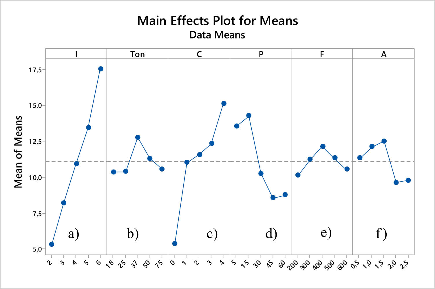
Minitab view of the influence of parameters on MRR.
The influence of technological parameters on MRR
| Levels | Technology parameters | |||||
|---|---|---|---|---|---|---|
| I | T on | C | P | F | A | |
| 1 | 5.319 | 10.367 | 5.347 | 13.565 | 10.122 | 11.348 |
| 2 | 8.219 | 10.399 | 11.038 | 14.281 | 11.238 | 12.137 |
| 3 | 10.922 | 12.775 | 11.573 | 10.262 | 16.153 | 12.510 |
| 4 | 13.430 | 11.314 | 12.347 | 8.552 | 11.345 | 9.632 |
| 5 | 17.531 | 10.566 | 15.116 | 8.761 | 10.563 | 9.794 |
| Influence level | 1 | 6 | 2 | 4 | 3 | 5 |
Pulse generation time (T on): T on = 18–37 µs produced a rise in spark energy, which in turn led to an increase in MRR, as seen in Figure 2b. On the other hand, at T on = 37–75 µs, it resulted in a drop in MRR. This is due to the fact that the pulse duration is too long, which also results in a reduction in the amount of time required for the formation of pulses. The amount of time required to expel the chip from the cutting area and for the dielectric fluid to recover will be decreased as a result of this. As a result, the machining process will be unstable, and a large number of short-circuit pulses will arise, which will result in a reduction in the efficiency of the machining process. The change in MRR in PMEDM with vibration applied to the workpiece is not substantial when compared to the value of T on = 18 µs. The MRR rises the most by 23.2% when the T on is equal to 37 µs.
Titanium powder concentration (C): This is the parameter with the second strongest influence on MRR, Table 2. Powder mixed into the dielectric fluid led to improved MRR, Figure 2c. The reason may be that the titanium powder entering the discharge gap has led to the formation of many discharge bridges, which leads to a significant increase in the number of sparks. On the other hand, powder mixed into the dielectric fluid will reduce the dielectric strength of the solvent, so the pulse energy loss for the breakdown of the dielectric fluid will also decrease. This results in increased useful energy for the melting and evaporation of the workpiece material. On the other hand, the discharge gap size also increases when the powder is mixed into the dielectric fluid. This will facilitate the process of pushing chips out of the discharge gap and lead to a reduction in the number of short circuit pulses and arc generation in the machining gap, so the machining process is more stable. Compared to no powder, powder mixed in a dielectric solution resulted in the largest increase in MRR of 182.7% at C = 4 g/l. The increase in powder concentration from 1 to 4 g/l led to an increase in MRR.
Dielectric fluid flow pressure (P): Dielectric fluid flow pressure has a strong influence on MRR in PMEDM with vibration associated with the workpiece (fourth strongest) (Table 2). Figure 2d shows that the fluid flow pressure dielectric fluid can lead to different MRR changes. The reason is that the pressure of the dielectric fluid flow affects the ability to push the chip out of the discharge gap, the stability of the dielectric fluid in the machining area, and the appearance of powder particles in the discharge gap. This has a very strong influence on the machining ability of PMEDM. When the dielectric fluid flow pressure is small, it will lead to the ejection of chip particles, powder, and solvent being affected by a slow electric spark, so the machining process will be less stable. On the other hand, when P is too large, it will lead to the existence of powder particles in a gap that is too short, and the formation of electric sparks with unstable high pressure. These things have an adverse effect on the machining process. P = 15 kPa will result in the largest MRR.
Vibration frequency (F): Is the parameter that has the third strongest influence on MRR (Table 2). Different vibration frequencies have led to MRR in PMEDM with vibration assigned to the workpiece changing differently (Figure 2e). The influence of vibration frequency will affect the formation and quantity of electric sparks and the stability of the machining process. F = 200–400 Hz leads to an increase in MRR and F = 500–600 Hz leads to a decrease in MRR. The reason for the influence of F on MRR has been clarified, MRR is largest at F = 400 Hz and smallest at F = 200 Hz.
Vibration amplitude (A): A parameter that does not greatly affect MRR in PMEDM (fifth level of influence) (Table 2). A = 0.5–1.5 µm led to increased MRR (Figure 2f). The reason may be that the amplitude affects the dielectric fluid pressure created between the electrode and the workpiece. When the amplitude increases in this range, the pressure increases to push the dielectric fluid out of the discharge gap, which will contribute to increasing the efficiency of pushing chips, powder, and dielectric fluid out of the machining area. Hence the machining process is more stable. However, A = 2.0–2.5 µm led to a sharp decrease in MRR, due to the large change in A leading to instability of the spark formation process at the discharge gap. MRR in PMEDM is largest at A = 1.5 µm.
3.2 Determine a set of technological parameters for machining productivity
The S/N ratio of MRR is analyzed in terms of larger is better. S/N analysis of MRR is shown in Figure 3. MRR in PMEDM with the largest vibration assigned to the workpiece with a reasonable set of parameters as follows: I = 6 A, T on = 37 µs, C = 4 g/l, P = 15 kPa, F = 400 Hz, A = 1.5 µm. The optimal result of MRR is determined according to formula (1) and MRRopt = 28.95 mm3/min. Experimental verification has obtained MRRopt = 31.29 mm3/min with an error of 8.08%.

Minitab view of the influence of technology parameters on S/N of MRR.
4 Conclusion
This study aims to determine the effect of adjusted technological parameters in PMEDM with low-frequency vibrations attached to the workpiece on MRR. The research results have drawn some conclusions as follows:
Since the current intensity significantly affects MRR, it is found as the most influential parameter.
The increase in I led to an increase in MRR, and the largest increase in MRR was 229.6% at I = 6 A.
T on has the weakest influence on MRR, and MRR is largest at T on = 37 µs.
Increasing C leads to increased MRR, and it is a parameter that significantly affects MRR.
MRR can be increased the largest by 182.7% at C = 4 g/l.
The MRRopt was 31.29 mm3/min in PMEDM using Cu electrode, SKD61 workpiece with I = 6 A, T on = 37 µs, C = 4 g/l, P = 15 kPa, F = 400 Hz, A = 1.5 µm.
-
Funding information: This research is funded by Hung Yen University of Technology and Education under grand number UTEHY.L.2022.12.
-
Author contributions: Dung Le Quang – Optimization, Phan Nguyen Huu – Optimization and ANOVA of the data, Muthuramalingam Thangaraj – Optimization, Dua Tran Van – Experiments, Thien Nguyen Van – Experiments.
-
Conflict of interest: There are no competing interests to be mentioned in the present study.
-
Ethical approval: There is no ethical approval needed in the present study.
-
Data availability statement: There is no need to mention the availability of data and materials in the present study.
References
[1] Ojha K, Garg RK, Singh KK. Effect of chromium powder suspended dielectric on surface roughness in PMEDM process. Tribol – Mater Surf Interfaces. 2011;5(4):165–71.10.1179/1751584X11Y.0000000021Search in Google Scholar
[2] Jeswani ML. Effects of the addition of graphite powder to kerosene used as the dielectric fluid in electrical discharge machining. Wear. 1981;70:133–9.10.1016/0043-1648(81)90148-4Search in Google Scholar
[3] Thesiya D, Rajurkar A. Aluminium powder mixed rotary electric discharge machining (PMEDM) on Inconel 718. Aust J Mech Eng. 2018;16(1):21–30.10.1080/14484846.2017.1294230Search in Google Scholar
[4] Uno Y, Okada A, Hayashi Y, Tabuchi Y. Surface integrity in EDM of aluminum bronze with nickel powder mixed fluid. J Jpn Soc Electr Mach Eng. 1998;32(70):24–31.10.2526/jseme.32.70_24Search in Google Scholar
[5] Gul IA, Abdul-Rani AM, Al-Amin M, Garba E. Elucidating powder-mixed electric discharge machining process, applicability, trends and futuristic perspectives. Machines. 2023;11(3):1–25.10.3390/machines11030381Search in Google Scholar
[6] Kansal HK, Singh S, Kumar P. Effect of silicon powder mixed EDM on machining rate of AISI D2 die steel. J Manuf Process. 2007;9(1):13–22.10.1016/S1526-6125(07)70104-4Search in Google Scholar
[7] Talla G, Gangopadhyay S, Biswas C. Effect of impregnated powder materials on surface integrity aspects of Inconel 625 during electrical discharge machining. Part B: J Eng Manuf. 2018;232(7):1259–72.10.1177/0954405416666904Search in Google Scholar
[8] Rathi MG, Mane DV. Study on effect of powder mixed dielectric in EDM of Inconel 718. Int J Sci Res Publ. 2014;4(11):1–7.Search in Google Scholar
[9] Molinetti A, Amorim FL, Soares PC, Czelusniak T. Surface modification of AISI H13 tool steel with silicon or manganese powders mixed to the dielectric in electrical discharge machining process. Int J Adv Manuf Technol. 2015;83(5–8):1057–68.10.1007/s00170-015-7613-1Search in Google Scholar
[10] Gunawan SP, Muslim M, Mohd H, Yoke SW, Norihisa M, Kimiyuki M. Study of workpiece vibration in powder-suspended dielectric fluid in micro-EDM processes. Int J Precis Eng Manuf. 2013;14:1817–22.10.1007/s12541-013-0243-3Search in Google Scholar
[11] Pay JL, Jiwang Y, Tsunemoto K. Fabrication of deep micro-holes in reaction-bonded SiC by ultrasonic cavitation assisted micro-EDM. Int J Mach Tools Manuf. 2014;76:13–20.10.1016/j.ijmachtools.2013.09.010Search in Google Scholar
[12] Gunawan SP, Tutik S, Muslim M. Improvement of machining time in micro-EDM with workpiece vibration and graphite powder mixed in dielectric fluid. Indian J Eng Mater Sci. 2012;19(6):375–8.Search in Google Scholar
[13] Quang DL, Huu PN, Tien LB, Duc TN. Comparative study of low-frequency vibrations assigned to a workpiece in EDM and PMEDM. Int J Mod Phys B. 2020;34(22n24):2040145.10.1142/S0217979220401451Search in Google Scholar
[14] Quang DL, Huu PN, Tien LB, Duc TN. Effect of low-frequency vibrations on MRR, EWR and Ra in powder-mixed electrical discharge machining. Int J Mod Phys B. 2020;34(22n24):2040145.10.1142/S0217979220401530Search in Google Scholar
[15] Fattahi H, Pak A. Investigation of ultrasonic assisted electro discharge machining with TiO2, Al2O3 and ZnO nano-powder. Amirkabir J Mech Eng. 2018;50(3):177–80.Search in Google Scholar
© 2024 the author(s), published by De Gruyter
This work is licensed under the Creative Commons Attribution 4.0 International License.
Articles in the same Issue
- Research Articles
- Evaluation of the mechanical and dynamic properties of scrimber wood produced from date palm fronds
- Performance of doubly reinforced concrete beams with GFRP bars
- Mechanical properties and microstructure of roller compacted concrete incorporating brick powder, glass powder, and steel slag
- Evaluating deformation in FRP boat: Effects of manufacturing parameters and working conditions
- Mechanical characteristics of structural concrete using building rubbles as recycled coarse aggregate
- Structural behavior of one-way slabs reinforced by a combination of GFRP and steel bars: An experimental and numerical investigation
- Effect of alkaline treatment on mechanical properties of composites between vetiver fibers and epoxy resin
- Development of a small-punch-fatigue test method to evaluate fatigue strength and fatigue crack propagation
- Parameter optimization of anisotropic polarization in magnetorheological elastomers for enhanced impact absorption capability using the Taguchi method
- Determination of soil–water characteristic curves by using a polymer tensiometer
- Optimization of mechanical characteristics of cement mortar incorporating hybrid nano-sustainable powders
- Energy performance of metallic tubular systems under reverse complex loading paths
- Enhancing the machining productivity in PMEDM for titanium alloy with low-frequency vibrations associated with the workpiece
- Long-term viscoelastic behavior and evolution of the Schapery model for mirror epoxy
- Laboratory experimental of ballast–bituminous–latex–roving (Ballbilar) layer for conventional rail track structure
- Eco-friendly mechanical performance of date palm Khestawi-type fiber-reinforced polypropylene composites
- Isothermal aging effect on SAC interconnects of various Ag contents: Nonlinear simulations
- Sustainable and environmentally friendly composites: Development of walnut shell powder-reinforced polypropylene composites for potential automotive applications
- Mechanical behavior of designed AH32 steel specimens under tensile loading at low temperatures: Strength and failure assessments based on experimentally verified FE modeling and analysis
- Review Article
- Review of modeling schemes and machine learning algorithms for fluid rheological behavior analysis
- Special Issue on Deformation and Fracture of Advanced High Temperature Materials - Part I
- Creep–fatigue damage assessment in high-temperature piping system under bending and torsional moments using wireless MEMS-type gyro sensor
- Multiaxial creep deformation investigation of miniature cruciform specimen for type 304 stainless steel at 923 K using non-contact displacement-measuring method
- Special Issue on Advances in Processing, Characterization and Sustainability of Modern Materials - Part I
- Sustainable concrete production: Partial aggregate replacement with electric arc furnace slag
- Exploring the mechanical and thermal properties of rubber-based nanocomposite: A comprehensive review
- Experimental investigation of flexural strength and plane strain fracture toughness of carbon/silk fabric epoxy hybrid composites
- Functionally graded materials of SS316L and IN625 manufactured by direct metal deposition
- Experimental and numerical investigations on tensile properties of carbon fibre-reinforced plastic and self-reinforced polypropylene composites
- Influence of plasma nitriding on surface layer of M50NiL steel for bearing applications