Multiaxial creep deformation investigation of miniature cruciform specimen for type 304 stainless steel at 923 K using non-contact displacement-measuring method
-
Noritake Hiyoshi


Abstract
Multiaxial creep investigations at high temperatures are required to guarantee the integrity of structural materials such as boiler pipes for power generation and turbine blades for aviation and industrial applications. The multiaxial creep testing method using a cruciform specimen has several advantages, and the authors successfully downsized the specimen. The authors also developed a technique for the in situ observation of the specimen in an electric furnace and the non-contact displacement measurement in the development of a biaxial tensile creep testing machine for the miniature cruciform specimen. By observing the specimen at a target mark during the creep testing through an observation window installed at the bottom of the furnace, it was possible to visualize the specimen surface variations and obtain the axial strain from the locus of the target marks. The Mises-type equivalent strain was calculated from the axial strains obtained in the equi-biaxial tensile multiaxial creep testing and was compared with the strains obtained in the uniaxial creep testing. The Mises-type equivalent strain can be expressed using a unified method up to approximately 5% of the initial strain in the test, even in the multiaxial stress state.
1 Introduction
The safety of high-temperature components such as power generation boiler piping and aero-engine turbine rotor blades requires proper investigation of structural materials. The structural components of high-temperature equipment are subjected to cyclic fatigue damage and creep damage owing to the high-temperature environment, and experimental evaluation under multiaxial stress conditions is required because of the complexity of their geometry and loading. Experimental methods for multiaxial creep testing include a method in which a round bar specimen with notches is tensioned and twisted [1–4], a hollow cylindrical specimen is subjected to tension, torsion [5–8], and internal and external pressures, and a cruciform specimen is tensioned [9–16]. The cruciform specimen has the advantage that the stress distribution is controlled uniformly at the center of the specimen and that the surface condition can be observed.
In material testing, miniaturization of the specimen size has many advantages, as seen in the small punch test and small punch creep test using disk-shaped specimens of approximately 8 mm in diameter [17–20] and the miniature creep test using round bar specimens of approximately 1–2 mm in diameter [21,22]. The smaller specimen size not only directly leads to a reduction in the volume of the material to be evaluated but also enables quantitative evaluation of the relationship between the thickness position and damage in thick-walled piping, e.g., if sampling techniques can be realized from arbitrary local positions on the actual machine [23]. However, in previous experimental research using cruciform specimens, the size of the specimen was approximately 190 mm in length [12,13]. A relatively large plate is required to prepare the testing specimens. In response to this background, the authors designed and developed a cruciform specimen of 50 mm in length and a biaxial tension-type multiaxial creep testing machine, and proposed a multiaxial creep testing method using the miniature specimen [11].
We have investigated the effect of multiaxial stress degrees on creep rupture lifetime by conducting uniaxial and multiaxial creep tests at 823 K (650°C) for Type 304 austenitic stainless steel [10]. In addition, when preparing a cruciform specimen of Super 304H from an actual piping material, the width of the sample material is limited owing to the pipe diameter. To solve this issue, the validity of using a weld-type cruciform specimen which is welded by electron beam welding method between the center gauge section and the applying load part was verified [9].
This study focused on creep deformation based on previously obtained creep study data for Type 304 stainless steel at 823 K (650°C). In situ observations in a high-temperature electric furnace were used to visualize the high-temperature deformation of the specimens and to discuss the crack initiation and propagation behavior.
2 Experimental procedure
2.1 Miniature specimen
The shape and dimensions of the cruciform specimen [10,11] are shown in Figure 1(a). The entire specimen had dimensions of 50 mm × 50 mm, with a 1 mm thickness center gauge section. An finite element (FE) analysis confirmed that the von Mises equivalent stress varies within a ±5% range at the center gauge section and because the σ z stress component is zero at the center gauge section, a plane stress condition is achieved with this particular shape and dimensions of the miniature cruciform specimen. Multiaxial stress testing was conducted using X- and Y-axis load settings for the cruciform specimen. Because the cruciform specimen does not have a definite cross-section, the relationship between the applied load and the generated stress was obtained by the FE analysis in advance. The designed cruciform specimen has a tensile loading arm length of approximately 20 mm, which is a relatively large ratio of its length to its overall dimensions. The reason for the large length is that bending deformation of the loading arms is inevitable when tensile load is applied to them, and this deformation generates bending stresses that may affect the stress distribution at the center gauge section. By setting the loading arm length to Figure 1(a), the effect of the bending mode of the arm on the stress distribution at the gauge section can be reduced. Figure 1(b) shows the shape and dimensions of the uniaxial testing specimen. Uniaxial data were obtained for the same material.

Shape and dimensions of miniature specimen for creep testing (mm): (a) cruciform specimen and (b) plate specimen for uniaxial loading.
2.2 Specimen surface observation method
Figure 2 shows an appearance of the multiaxial creep testing machine for the cruciform specimen. Figure 2(a) shows the configuration and the main dimensions of the testing machine, which was installed with dimensions of 600 mm × 600 mm and a height of 1,000 mm. Figure 2(b) shows a photograph of the electric furnace of the biaxial tensile creep testing machine developed for the miniature cruciform specimens. The furnace has a 1 kW heating capacity and is of the upper and lower two-split type. The figure shows the lower part of the furnace, which was installed with quartz glass at the bottom to observe the inside of the furnace. Figure 2(c) shows the setup of the furnace and the optical camera used to observe the interior of the furnace. The deformation of the specimen was visualized by observing it in an electric furnace and periodically capturing photographs. In addition, the displacement was measured using a non-contact method by quantifying the trajectory of target marks marked on the specimen.


Appearance of tensile creep testing machine for miniature cruciform specimen: (a) schematic figure of the testing machine, (b) electric furnace with observation window (lower part), and (c) setup of an electric furnace and an optical camera for observation.
The verification results of the non-contact displacement measurement method are shown in Figure 3. The tensile tests described below were performed using a conventional tensile testing machine and a high-temperature tensile testing machine with an electric furnace with an observation window. Figure 3(a) shows the results of the tensile test of the aluminum alloy plate specimen at room temperature. The strain in the direction of the tensile axis (Y-axis) and the strain perpendicular to the tensile axis were measured using the strain gauges. In addition, the target marks on the specimen were photographed and measured using the non-contact displacement measurement method described earlier, and the trajectories were quantified. The circular plots in the figure show the Y- and X-axis strains obtained by the non-contact displacement measurement method. The solid lines represent the strain gauge results. The strain obtained by the non-contact displacement measurement method is almost the same as that obtained by the strain gauges, and it can even measure large deformations that are difficult to measure using strain gauges.

Verification results of non-contact displacement measurement methods: (a) strain measurement results of aluminum alloys at room temperature and (b) displacement measurement results of stainless steel at high temperature.
Figure 3(b) shows the tensile test results for the Type 304 stainless steel at 573 K. Displacement at the gauge part is measured in an electric furnace using a non-contact displacement measurement method through an observation window of the furnace. Multiple verifications showed that the relationship between the displacement measured by the LVDT (δ LVDT) and the displacement measured by the optical camera (δ CCD) was 0.96 and 1.06. The reasons for the differences in the calculated values may be due to the long distance between the camera lens and the specimen gauge part in the electric furnace, or errors in the results due to the small number of tensile testing datasets verified. Although the reasons for the differences in the calculated values are not clear, it is considered that the non-contact displacement measurement method can be used in high-temperature environments when applying this method to creep tests for the miniature cruciform specimens, because the distance between the camera lens and the specimen point is small, as shown in Figure 2(c).
2.3 Experimental conditions
Multiaxial creep tests were conducted using the cruciform specimen and the biaxial tensile creep testing machine. Type 304 austenitic stainless steel was used for the tests; its chemical composition is listed in Table 1. The testing temperature was 923 K (650°C). The testing temperature was increased from room temperature to the target temperature within approximately 2 h, and the tests were started after approximately 30 min of heat equalization. We verified that the temperature distribution at the center gauge section of the cruciform specimen is within a tolerance of ±1.1 K at 923 K in advance.
Chemical composition of tested materials (mass%)
| C | Si | Mn | P | S | Ni | Cr | Co |
|---|---|---|---|---|---|---|---|
| 0.06 | 0.56 | 1.48 | 0.033 | 0.025 | 8.16 | 18.30 | 0.19 |
Heat treatment at 1,323 K × 120 s, W.Q.
The principal stress ratio (λ) defined by Eq. (1) was used to express the multiaxiality in this study. The ratio is calculated as the ratio of the maximum principal stress (σ 1) to the minimum principal stress (σ 3) and is equal λ to 0 for uniaxial tension and λ = 1 for equi-biaxial tension:
3 Results and discussion
3.1 Fracture direction of cruciform specimen
Creep testing was conducted at two levels of Mises-type equivalent stress (σ eq); 200 MPa and 180 MPa, for λ = 0 and λ = 1 conditions. The creep rupture lifetimes are presented in Table 2. There were no significant differences in the creep rupture lifetimes when compared at the same equivalent stress, although the results for λ = 1 were slightly shorter than those for λ = 0.
Creep rupture lifetime at 923 K
| Temperature (T, K) | Principal stress ratio (λ) | von Mises equivalent stress (σ eq, MPa) | Rupture time (t r, h) |
|---|---|---|---|
| 923 | 0 | 200 | 446 |
| 0 | 180 | 1,034 | |
| 1 | 200 | 329 | |
| 1 | 180 | 635 |
Figure 4 shows the photographs of the specimen after the creep testing. The results for λ = 0 are shown in Figure 4(a) and (b). The specimen fractured ductility in a direction perpendicular to the tensile axial direction. Figure 4(c) shows the results at σ eq = 200 MPa for λ = 1. Crack initiation will be described later, but several cracks at the center gauge section grew in the direction perpendicular to the principal direction of maximum stress, leading to rupture. Figure 4(d) shows the results for σ eq = 180 MPa at λ = 1. Similar to the σ eq = 200 MPa results, the specimen ruptured owing to crack propagation at the center gauge section, but the direction of macroscopic propagation was approximately 45° to the direction of the principal stress. The macrocrack propagation direction of the main crack was different depending on the equivalent stress; however, this difference and its propagation mechanism are not yet understood. Further studies, such as measurement of the fracture surface angle and numerical analysis of the difference in stress distribution in the specimen thickness direction with increasing or decreasing stress and duration of the test, are required in the future.
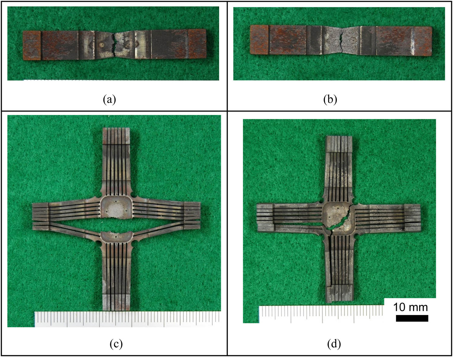
Overall photographs of ruptured specimens: (a) λ = 0, σ = 200 MPa, (b) λ = 0, σ = 180 MPa, (c) λ = 1, σ eq = 200 MPa, and (d) λ = 1, σ eq = 180 MPa.
3.2 Multiaxial creep deformation
Figure 5 shows an example of a series of observation photographs of the specimen placed in the electric furnace during the creep test. Figure 5(a) shows the results at λ = 1 and σ eq = 200 MPa, expressed as the rupture lifetime ratio. The center gauge section of the specimen was polished with emery paper up to #2000 and buffed with alumina powder before the test, and a metallic luster was observed in the early stage of its life (0.1 t r, 0.2 t r). However, high-temperature oxidation can be observed over time. The unevenness at the center gauge section can be observed from approximately 0.4 t r, suggesting that the grain boundary has been damaged and small cracks have appeared. The main cracks, which may have been caused by the propagation of small cracks and their linkage, were observed from 0.9 t r onward.

Example of time series variation of the miniature cruciform specimen in the electric furnace. : (a) λ = 1, σ eq = 200 MPa and (b) λ = 1, σ eq = 180 MPa.
Figure 5(b) shows the results for λ = 1 and σ eq = 180 MPa. The deformation of the cruciform specimen in the high-temperature environment was similar to that of the σ eq = 200 MPa specimen shown in (a), i.e., unevenness was observed at the center gauge section from mid-life, and small cracks grew into macrocracks, leading to specimen rupture. Using an optical camera to observe specimens in the electric furnace, it was possible to visualize the deformation of the specimens and the initiation and propagation of cracks from the grain boundaries and other points. The effectiveness of this method was confirmed, as it has been generally difficult to observe the deformation of specimens in a closed electric furnace.
3.3 Strain under multiaxial stress
As shown in Figure 5, the target marks of approximately 0.3 mm diameter were marked with heat-resistant ink in the direction of the tensile loading axis at the specimen center gauge section. The relative distances between the two target marks in the Y- and X-axis directions were computed using image analysis, and the displacement of the center gauge section was obtained.
Figure 6 shows the creep curve obtained using the non-contact displacement measurement method. Both σ eq = 200 and 180 MPa, indicated by the square and circle marks, respectively, show that the nominal strain from the beginning of the testing could be drawn. In both cases, the creep curves show that the steady-state region was followed by acceleration to rupture. At σ eq = 200 MPa, the Y-axis strain, indicated in blue, was larger than the X-axis strain, indicated in red. As shown in Figure 4(c), the main crack at λ = 1 and σ eq = 200 MPa grew in the Y-axis direction, resulting in larger deformation in the Y-axis direction. The deformation up to creep rupture was visualized and quantified from the observation photographs of the specimen in the electric furnace.

Time-strain curves for the miniature cruciform specimen.
Based on the Y- and X-axis strains obtained using the cruciform specimen, as shown in Figure 6, a uniform creep curve drawing was considered. The thickness direction strain (Z-axis) was obtained using the volume invariant rule, as shown in Eq. (2).
The axial strains ε x and ε y in the biaxial tensile creep testing are considered to be the principal strains ε 1 and ε 3. Furthermore, the normal strain ε z in the thickness direction calculated by Eq. (2) is considered to be the principal strain ε 2, and the equivalent Mises-type strain is calculated by the following Eq. (3):
Figure 7 shows the Mises-type equivalent strain curves obtained from the multiaxial creep test at λ = 1. Figure 7(a) shows the results for σ eq = 200 MPa, together with the results at λ = 0 using the specimen shown in Figure 2(b), and the creep curve obtained using a standard round bar specimen obtained from the same heat material. Because the creep rupture lifetimes of the miniature specimens λ = 1, λ = 0, and the standard specimens do not exactly correspond, the lifetimes are normalized to the respective rupture lifetimes. It can be observed that the equivalent strain at the early stage of the test up to approximately 5% can be uniformly expressed by the equivalent volume of the Mises-type. After 5%, the results for the standard and λ = 0 miniature specimens are almost the same, but for λ = 1, the equivalent amount at the latter stage of life is lower. The strain at the final rupture was approximately half that of other specimens at λ = 1.

Creep curve with Mises-type equivalent strain: (a) σ eq = 200 MPa and (b) σ eq = 180 MPa.
Figure 7(b) shows the results for σ eq = 180 MPa. Although the strain in the standard specimen is slightly smaller than that in the others, the Mises-type can be evaluated uniformly up to approximately 5% of the early stage of the test, similar to the trend at σ eq = 200 MPa. The strain at the final rupture at λ = 1 was slightly smaller than the other results, suggesting that the ductility calculated as the Mises-type equivalent may be reduced under multiaxial stress conditions. The reduction in creep rupture ductility under multiaxial stress may depend on the stress level and temperature, and more experimental data are required in the future.
4 Conclusions
High-temperature multiaxial creep testing of Type 304 stainless steel was conducted using the miniature cruciform specimen. Creep deformation was investigated by in situ observation of the specimens in the electric furnace.
The specimens were periodically photographed in the electric furnace, which enabled non-contact measurement of the displacement at the center gauge section of the specimen at high-temperature creep. It was also possible to measure the strain just before rupture.
The center gauge section exhibited unevenness, which appeared to be caused by intergranular cracking as the testing time elapsed. The intergranular cracks grew into macroscopic cracks by propagating and connecting, resulting in ruptures.
The macroscopic direction of crack propagation under equi-biaxial tensile conditions was perpendicular to the principal stress axis at an equivalent stress of 200 MPa, while the direction of crack propagation at 180 MPa was 45° to the principal stress axis.
Initial creep up to approximately 5% could be uniformly represented using the Mises-type equivalent strain.
Acknowledgement
The author would like to acknowledge the graduates of the University of Fukui who worked on the foundational challenges of this subject.
-
Funding information: This work was supported by JSPS KAKENHI Grant Numbers JP19K04089 and JP22K03807.
-
Author contributions: Noritake Hiyoshi: conceptualization, investigation, project administration, writing.
-
Conflict of interest: The author declares no conflict of interest.
References
[1] Alang NA, Nikbin K. A new approach to predict creep rupture of Grade 92 steel under multiaxial stress states. Int J Mech Sci. 2019;163:105096.10.1016/j.ijmecsci.2019.105096Search in Google Scholar
[2] Mao J, Li X, Bao S, Ge R, Yan L. The experimental and numerical studies on multiaxial creep behavior of Inconel 783 at 700 °C. Int J Press Vessel Pip. 2019 Jun;173:133–46.10.1016/j.ijpvp.2019.05.005Search in Google Scholar
[3] Chang Y, Xu H, Ni Y, Lan X, Li H. Research on representative stress and fracture ductility of P92 steel under multiaxial creep. Eng Fail Anal. 2016 Jan;59:140–50.10.1016/j.engfailanal.2015.09.011Search in Google Scholar
[4] Takahashi Y. Creep rupture behavior of modified 9Cr-1Mo steel under multiaxial stress and its modeling. Zair Soc Mater Sci Japan. 2009;58(2):115–21.10.2472/jsms.58.115Search in Google Scholar
[5] Hiyoshi N, Matsumoto R. Creep deformation and creep rupture life evaluation for type 304 stainless steel under tension-torsion multiaxial loading. J Soc Mater Sci Japan. 2022;71(2):175–80.10.2472/jsms.71.175Search in Google Scholar
[6] Hiyoshi N, Iriyama Y. Development of tension-torsion multiaxial creep testing apparatus for heat resisting steel. MATEC Web Conf. 2018;159:02015.10.1051/matecconf/201815902015Search in Google Scholar
[7] Hamada N, Maruyama M, Umeda H. Creep strength of Mod.9Cr1Mo steel under biaxial stress states. Trans JSME (in Japanese). 2014;80(817):1–9.10.1299/transjsme.2014smm0146Search in Google Scholar
[8] Niu LB, Kobayashi M, Takaku H. Creep rupture properties of an austenitic steel with high ductility under multi-axial stresses. ISIJ Int. 2002;42(10):1156–61.10.2355/isijinternational.42.1156Search in Google Scholar
[9] Hiyoshi N, Tsuboyama K, Zhang S, Itoh T, Sakane M. Multiaxial creep rupture lifetime evaluation for Super304H using weld-type miniature cruciform specimen. Zair Soc Mater Sci Japan. 2023;72(2):105–1.10.2472/jsms.72.105Search in Google Scholar
[10] Hiyoshi N, Itoh T, Sakane M, Tsurui T, Tsurui M, Hisaka C. Development of high temperature multiaxial creep properties evaluation method for type 304 stainless steel using miniature cruciform specimen. J Soc Mater Sci Japan. 2021;70(2):93–8.10.2472/jsms.70.93Search in Google Scholar
[11] Hiyoshi N, Itoh T, Sakane M, Tsurui T, Tsurui M, Hisaka C. Development of miniature cruciform specimen and testing machine for multiaxial creep investigation. Theor Appl Fract Mech. 2020 Aug;108:102582.10.1016/j.tafmec.2020.102582Search in Google Scholar
[12] Kobayashi H, Ohki R, Itoh T, Sakane M. Multiaxial creep damage and lifetime evaluation under biaxial and triaxial stresses for type 304 stainless steel. Eng Fract Mech. 2017 Apr;174:30–43.10.1016/j.engfracmech.2017.01.001Search in Google Scholar
[13] Zhang S, Abe K, Wakai T, Sakane M. Multiaxial creep lifetime assessment for type 304 stainless steel. Proceedings of the 12th International Conference on Creep and Fracture of Engineering Materials and Structures. 2012.Search in Google Scholar
[14] Zhang S, Wakai T, Sakane M. Creep rupture life and damage evaluation under multiaxial stress state for type 304 stainless steel. Mater Sci Eng A. 2009 Jun;510–511:110–4.10.1016/j.msea.2008.04.113Search in Google Scholar
[15] Fujimoto M, Sakane M, Date S, Yoshida H. Multiaxial creep rupture and damage evaluation for 2.25Cr-1Mo forged steel. J Soc Mater Sci Japan. 2005;54(2):149–54.10.2472/jsms.54.149Search in Google Scholar
[16] Mukai S, Takada T, Sakane M, Ohnami M, Tsurui T. Development of multiaxial creep testing machine using cruciform specimen. J Soc Mater Sci Japan. 1996;45(5):559–65.10.2472/jsms.45.559Search in Google Scholar
[17] Welschen R, Naziris F, Pierick PT, Kolluri M. Small punch test setup for in-cell testing of irradiated materials. Mater Perform Charact. 2022;11(3):351–9.10.1520/MPC20210113Search in Google Scholar
[18] Abendroth M, Hasche A, Zineb TB, Kiefer B. Characterization of iron-based shape memory alloys using the small punch test. Mater Perform Charact. 2022;11(3):335–50.10.1520/MPC20210122Search in Google Scholar
[19] Richardson M, Gorley M, Wang Y, Andres D, Dawson H. Small punch creep investigation of Eurofer97 and 14Cr oxide dispersion strengthened steel. Nucl Mater Energy. 2021;29(May):101067.10.1016/j.nme.2021.101067Search in Google Scholar
[20] Wang LY, Wang YC, Zhou ZJ, Wan HY, Li CP, Chen GF, et al. Small punch creep performance of heterogeneous microstructure dominated Inconel 718 fabricated by selective laser melting. Mater Des. 2020;195:109042.10.1016/j.matdes.2020.109042Search in Google Scholar
[21] Nakatsuka H, Katoh K, Naitoh T, Tomobe M, Nitta A. Evaluation of internal pressure creep rupture life of boiler tube using miniature tensile creep test. Mater Perform Charact. 2022;11(3):1–17.10.1520/MPC20210107Search in Google Scholar
[22] Hiyoshi N, Itoh T, Yamamoto T, Kanayama H. Challenge of establishing materials testing standards with miniature specimen for solders. Mater Perform Charact. 2022;11(3):464–73.10.1520/MPC20210099Search in Google Scholar
[23] Tsurui M, Hisaka C, Takahashi K, Nitta A, Yaguchi M. Optimization and verification of ultra-miniature specimen for evaluating creep property of in-service component material under uniaxial loading. Mater Perform Charact. 2022;11(3):385–401.10.1520/MPC20210106Search in Google Scholar
© 2024 the author(s), published by De Gruyter
This work is licensed under the Creative Commons Attribution 4.0 International License.
Articles in the same Issue
- Research Articles
- Evaluation of the mechanical and dynamic properties of scrimber wood produced from date palm fronds
- Performance of doubly reinforced concrete beams with GFRP bars
- Mechanical properties and microstructure of roller compacted concrete incorporating brick powder, glass powder, and steel slag
- Evaluating deformation in FRP boat: Effects of manufacturing parameters and working conditions
- Mechanical characteristics of structural concrete using building rubbles as recycled coarse aggregate
- Structural behavior of one-way slabs reinforced by a combination of GFRP and steel bars: An experimental and numerical investigation
- Effect of alkaline treatment on mechanical properties of composites between vetiver fibers and epoxy resin
- Development of a small-punch-fatigue test method to evaluate fatigue strength and fatigue crack propagation
- Parameter optimization of anisotropic polarization in magnetorheological elastomers for enhanced impact absorption capability using the Taguchi method
- Determination of soil–water characteristic curves by using a polymer tensiometer
- Optimization of mechanical characteristics of cement mortar incorporating hybrid nano-sustainable powders
- Energy performance of metallic tubular systems under reverse complex loading paths
- Enhancing the machining productivity in PMEDM for titanium alloy with low-frequency vibrations associated with the workpiece
- Long-term viscoelastic behavior and evolution of the Schapery model for mirror epoxy
- Laboratory experimental of ballast–bituminous–latex–roving (Ballbilar) layer for conventional rail track structure
- Eco-friendly mechanical performance of date palm Khestawi-type fiber-reinforced polypropylene composites
- Isothermal aging effect on SAC interconnects of various Ag contents: Nonlinear simulations
- Sustainable and environmentally friendly composites: Development of walnut shell powder-reinforced polypropylene composites for potential automotive applications
- Mechanical behavior of designed AH32 steel specimens under tensile loading at low temperatures: Strength and failure assessments based on experimentally verified FE modeling and analysis
- Review Article
- Review of modeling schemes and machine learning algorithms for fluid rheological behavior analysis
- Special Issue on Deformation and Fracture of Advanced High Temperature Materials - Part I
- Creep–fatigue damage assessment in high-temperature piping system under bending and torsional moments using wireless MEMS-type gyro sensor
- Multiaxial creep deformation investigation of miniature cruciform specimen for type 304 stainless steel at 923 K using non-contact displacement-measuring method
- Special Issue on Advances in Processing, Characterization and Sustainability of Modern Materials - Part I
- Sustainable concrete production: Partial aggregate replacement with electric arc furnace slag
- Exploring the mechanical and thermal properties of rubber-based nanocomposite: A comprehensive review
- Experimental investigation of flexural strength and plane strain fracture toughness of carbon/silk fabric epoxy hybrid composites
- Functionally graded materials of SS316L and IN625 manufactured by direct metal deposition
- Experimental and numerical investigations on tensile properties of carbon fibre-reinforced plastic and self-reinforced polypropylene composites
- Influence of plasma nitriding on surface layer of M50NiL steel for bearing applications