Mechanical behavior of thin-walled steel under hard contact with rigid seabed rock: Theoretical contact approach and nonlinear FE calculation
-
Aditya Rio Prabowo
 ,
Tuswan Tuswan
,
Tuswan Tuswan

Abstract
This work aims to investigate the mechanical behavior of steel-plated structures under a raking incident and to quantify the effect of the mesh size in nonlinear finite element (NLFE) analysis. To conveniently comprehend nonlinear phenomena, i.e., the grounding which takes place in this work, a series of theoretical contact formulations was defined. In the main analysis, raking, which is a part of the grounding scenario, was strictly assumed as contact between a tanker, which was assumed to have thin-walled steel, and a seabed rock in the form of a solid obstruction. Designed raking scenarios were calculated using the FE method by using the nonlinear phenomena of the material behavior in the calculation. The findings of this work indicated that the possibility of expanding the recommended mesh size in FE simulation should be evaluated by quantifying the behavior of structural responses, such as energy, the force damage pattern, and acceleration, subjected to a variety of applied meshing techniques. The results concluded that a notable difference occurred when the mesh size was more than 132 mm (ratio 11 based on the plate dimension in this work), and this size is strictly recommended to be used for calculation of the element length-to-thickness (ELT) ratio. Assessment in time simulation showed that applying larger mesh sizes will reduce the simulation time but increase the maximum values of the crashworthiness parameters, i.e., energy, force, acceleration, and displacement.
1 Introduction
The topic of ship structures covers a wide range of constructional arrangements, from high-speed crafts with leading naval technology to commercial-dangerous carriers, e.g., chemical tankers, LNG carriers, and nuclear vessels. During their operational time at sea, these structures may face accidental loads which threaten the safety of the ship structures themselves or even the cargo. Massive losses due to accidental loads have been experienced globally, and these have triggered a series of developments in ship structures [1]. This started from the most famous ship collision, the disaster of the Titanic in the Atlantic Ocean during her journey from England to the United States in 1912. More than 1500 human lives were estimated to have been lost after the investigation was completed. In one of the worst accidents in American–Canadian marine history, the RMS Empress of Ireland collided with a smaller carrier in heavy fog. This accident itself claimed the lives of approximately 1012 people, including the ship's crew. A year after the disaster of the RMS Empress of Ireland, a British ocean liner, the RMS Lusitania, was hit by a German torpedo, sinking within 18 minutes after the initial contact. More recently, in the late 20th century, many disasters have been caused by environment pollution due to oil spills after ships have been grounded. The oil spill caused by the Exxon Valdes in 1989, leading to a remarkable number of casualties, was still not the worst disaster in the history of shipping and offshore development. Eleven years prior to this accident, the Amoco Cadiz ran aground off Brittany, France, after its steering failed in a severe storm. An approximation of the oil spillage reached 68.7 million gallons, endangering marine life around both France and England.
Ship grounding itself [2,3,4,5,6] is defined as an impact phenomenon of a ship/vessel subjected to contact with a seabed or waterway side during its operation. Groundings may occur as an intentional event, such as in forms of beaching on land and careening for maintenance or repair purposes. On the other hand, grounding is also caused by unintentional events, such as marine accidents. Severe groundings deliver extreme loads on ship structures, causing immense losses, including hull breaches, cargo spills, total vessel loss, and human casualties. In less severe incidents, grounding may cause only local damage to the outer hull. Causes of grounding incidents include:
Current/water flow;
Darkness and less visibility;
Tide and sea states;
Visibility due to fog and other obstructions;
Wind and weather conditions;
Depth of waterways;
Geometry of waterways;
Density of traffic volume;
History of grounding accidents;
Distribution of water depth;
Age of vessel;
Size of vessel;
Type of vessel;
Speed of vessel;
Human and organizational factors;
War, terror attack, and piracy.
In terms of vessel velocities during accidents, groundings are initially classified as powered and drifting groundings. Powered groundings occur when the vessel moves due to its operation or when the propulsion system provides thrust during contact between the vessel and the rock. Drifting grounding happens when the vessel is in a stationary state or when the propulsion does not give any thrust to move the vessel. Waves and the sea state are external forces that can affect the vessel, potentially causing obstructions. For classifications based on the obstruction type, groundings are divided into hard and soft groundings. A hard grounding is an accident where the vessel structure is directly damaged due to contact between the structure and the obstruction. A soft grounding delivers damage (mostly initiated by a vertical crack) on the vessel structure due to the misplaced position of the ship during grounding. Uneven weight distribution of the ship structure during grounding causes damage to the vessel structure. Illustrations of these categories are displayed in Figure 1. Based on the accident conditions, groundings are divided into raking and stranding. Raking is a state where the bottom structure of a ship is breached by obstructions (e.g., seabed rock) in the longitudinal direction or same direction of the ship's movement. In this case, the ship is still capable of move in a certain velocity, which can cause immense and global longitudinal damage. On the other hand, stranding occurs when the obstructions penetrate the ship structure, mostly in the vertical direction (height of ship), causing localized damage, and ships that become stuck need evacuation to be removed from their locations. Along with local damage, stranding may cause cargo spills, as penetration in the vertical direction can breach the main cargo hold. The rising number of oil spills in marine transport and related industries are leading to chains of events that will unavoidably ruin maritime ecosystems and lead to species extinction.
![Figure 1 Schematic illustration of ship-grounding-based ship velocity [7]](/document/doi/10.1515/jmbm-2021-0016/asset/graphic/j_jmbm-2021-0016_fig_001.jpg)
Schematic illustration of ship-grounding-based ship velocity [7]
Designing solutions to satisfy two important terms, shipping safety and marine pollution, is a complicated challenge. The protection of the marine environment here is classified into two terms: active and passive methods. In the first method, active, numerous improvements to navigational and sailing instruments have been conducted to provide better ship operability, especially in critical conditions (fog, heavy sea and narrow waterways) and extreme regions (the Arctic [8, 9], and disaster-prone regions). These efforts aim to avoid such accidental loads (for example, collisions and groundings) from taking place so that the risks of oil spillage and foundering can be reduced as much as possible. The second method, passive, is performed by sustained research and assessment of structural crashworthiness against collisions and groundings. The objective of this method is to minimize both structural and environmental casualties after loads take place on ships, expanding the mitigation period and rescue operation time. The sustained terminology in this method is chosen since various scholars have realized that despite the advanced development of navigational instruments and structural arrangements, accidental loads can still occur [10,11,12,13]. Continuous effort and research in this area has been conducted by relevant parties in naval architecture and marine structures, and their research can be classified into several groups according to the research methodology, such as analytical theory, empirical formulae, experimental tests and numerical simulation.
From these groups, numerical simulation is considered to be capable of producing similar results to real phenomena within reasonable research fund and time processes. However, many problems in the field of accidental loads for marine structures require more recent investigation and evaluation due to the nature of collisions and groundings as nonlinear phenomena. Advanced computational methodology, such as the Finite Element (FE), is also taken as a decent solution for calculating structural responses. However, the consideration of virtual parameters and their influence on calculation results while conducting the FE method is often neglected to a certain degree. This case has a major influence on a user who performs numerical simulation using low-to-average computational instruments. Furthermore, time analysis will be large, and generally it will not be acceptable, especially with nonlinear phenomena. Large times are heavily affected by the application of an arbitrary fine mesh, such as those applied by Kõrgesaar et al. [14], Heinvee and Tabri [15], and Sun et al. [16]. It will not be a problem if the calculation instrument is included in the high-performance type, but this strategy is not fully applicable for users with an average-performance computer. One of the most popular solutions to solve this problem is the application of a larger mesh size to the analyzed model to reduce the time analysis. Nevertheless, one risk of this solution is that the obtained solution will not be similar or even very distinct compared to the benchmark. Therefore, there is a need to assess the meshing strategy size, which requires strict implementation.
The focus of the current study is to assess the mechanical behaviors of thin-walled steel structures, i.e., ship hulls under an accidental grounding situation. The ship will be visualized as an arrangement of thin-plated structures and will be interacting with the seabed during its operation. Numerical parameters, i.e., the mesh size on the finite element model, are varied and applied to compile an investigation summary regarding the effects of the mesh size on the crashworthiness parameters. Further, an evaluation of the results will provide an estimation that will assist with expanding the current meshing strategy so that calculation times can be improved without neglecting the reliability aspect or similarity of the calculation results of the selected reference.
2 Fundamentals of contact mechanics
Ship groundings are set as a contact interaction between the ship structure and seabed. In this case, the fundamental contact mechanic itself needs to be defined in an analytical approach before a more complex system is simulated using the nonlinear finite element method. For concise contact assumption, during contact between two entities, their bodies/parts of their bodies collide with a certain velocity at an initial so-called incidence. After the incidence, an interpenetration takes place in a small area of the contact between the two entities, which is relative to the characteristics of the collided entities. Both of them can be deformed, as in the case of deformable-to-deformable contact, or only one of them can be, as in deformable-to-rigid contact, or they can even bounce off in opposite directions, as in rigid-to rigid contact. Based on the analytical illustration in Figure 2, a series of contact formulations can be derived into the following: the impulse, motion (translation and rotation), velocity, and inverse inertia, as presented in Eqs. (1)–(15) (details regarding notation can be reviewed in Liu and Amdahl [17]).
![Figure 2 Illustration of collision between two rigid bodies [17]](/document/doi/10.1515/jmbm-2021-0016/asset/graphic/j_jmbm-2021-0016_fig_002.jpg)
Illustration of collision between two rigid bodies [17]
Impulses Pi(t) and
Translation and rotational motions:
and
Velocity:
Relative velocity:
Change in impulses:
We conclude that
where the elements of the inverse inertia matrix
With the assumption that the inverse inertia matrix is symmetric, i.e.,
It is noted that the matrix Iij of the moments and products of inertia has an inverse, as denoted by
Results of the contact may appear in the forms of local deformation and consequent indentation due to the pressure on the area of contact. During impact, the interpenetration produces a resultant force of action or reaction that works in opposite directions to the two entities and thereby resists interpenetration. Due to its nature, several pioneer works used the force to describe structural resistance during impact [18,19,20]. On initial contact, the force will increase with deeper penetration and more indentation on the contact area, while, to a certain degree, a reduction in speed occurs and contact is stopped. According to [21], at the instant of impact, the work done by the contact force is sufficient to reduce the collided entities’ velocities to zero. In solid problems, the contact force acting in a collision is a product of the local deformations, and is required for the two entities’ surfaces to settle in the area of contact. The local deformation and indentation pattern, which occurs during impact, is closely related to the ship velocity and material properties. Considering the velocity, the consequence of a low-speed impact is predicted to be minor deformation, and high intensity should solely be found near the area of contact.
At higher speeds, larger damage is expected, as the collided entities will experience excessive strain. Such situations will provide easy observation of the damaged parts, as large localized deformation may appear as forms cratering or as penetration. These descriptions are summarized with the assumption that the speed of the collided entities is initial. The clearest result of the initial speed is the crashworthiness criterion of kinetic energy, where kinetic energy gets reduced as penetration increases (for application in ship–ship impacts, see [22]). By applying a uniform velocity on the collided bodies, it is also possible that large amounts of damage will take place. A series of experimental tests, followed by virtual calculations, have verified this characteristic [23,24,25,26,27,28].
3 Algorithms and modelling nonlinear problems
The impact of any collided object generally happens in a spontaneous time span, with a high load rate experienced by the involved entities. The nature of impacts here requires adequate understanding to obtain valid results with a reasonable time process by the finite element method (see goal setting of FE simulation in [29]). A short-time process is matched with the characteristic of explicit methodology, which requires very small time steps to maintain the stability limit. In a similar fashion, impacts which possess high nonlinearities are indeed characterized by time-consuming analysis.
The explicit methodology presents an effective assumption that all nonlinearities, including contact, are included in the internal force vector, so that no inversion for the stiffness matrix is required. When performing this calculation strategy, a central difference time integration is used. Acceleration is evaluated at time t as given in Eqs. (16) and (17). After that, the velocity and displacement are evaluated (Eqs. (18) and (19)). The condition of the geometry is updated by adding the displacement increments to the initial condition x0 (Eq. (20)). Consideration of the stability limit is strictly applied at the explicit strategy, which states that the solution is solely stable if the time step size is smaller than the critical size, as shown in Eq. (21). In the explicit algorithm of FE codes ANSYS LS-DYNA [30], a scale factor of 0.9 is selected to decrease the time step and keep the calculation process in a stable state.
Here, [M] is the mass matrix; {Ftext} is the applied external and body force vector; {Ftint} is the internal force vector; {at} is the acceleration at time t; Fhg is the hourglass resistance force, Fcontact is the contact force; BT is the body force; σn is the internal stress; Ω is the solid volume.
The challenge in designing virtual geometries subjected to large deformations is that one-point (reduced) integration solid and shell elements are susceptible to zero-energy modes, or so-called hourglass modes. The ANSYS LS-DYNA user's guides [30] describe these phenomena as oscillatory in nature and as tending to have periods much shorter than those of the overall structural response. In other words, according to mathematical states, it is not physically possible that they occur. They have no stiffness, appear as a zigzag pattern on a meshed geometry, and make numerical solutions less accurate. Based on this description, it is recommended to always minimize the hourglass which often appears in the analysis of nonlinear problems such as collisions and groundings. Two possible methods to control the hourglass can possibly be applied to numerical configurations. The first option is adding stiffness to the structural geometry to resist the hourglass modes. However, this option will not affect the rigid body motions and linear deformation fields. The second option is to damp velocities in the direction of the hourglass modes. Another more practical solution is to apply fully integrated formulations to the numerical geometry. This formulation will avoid the structural elements that experience the hourglass modes, with the consequence that it will increase the simulation time.
Here, {vt} is the velocity at time t; {ut} is the displacement at time t; {x0} is the initial geometry; {xt} is the updated geometry at time t; Δtt is the difference in time at time t compared to the initial/selected condition; Δtcrit is the critical time step size; ωmax is the largest natural circular frequency.
4 Preparation and setting of impact analysis
4.1 Model validation
Previous work of Alsos [31, 32] regarding the penetration test of the simplified side hull is used as a benchmark reference for this work. The test is widely used as a validation reference for any impact phenomena, including by AbuBakar and Dow [33] for ship grounding, and their results will also be used as comparative data for the results of this benchmark study. A technical drawing of the model is presented in Figure 3; the plate panel was supported by a hollow frame, and the lower side of the plate was attached by a stiffener in the form of a flat bar. Characteristic details of the applied material on the panel are presented in Table 1.
![Figure 3 Designed plate panel for the penetration test [31]](/document/doi/10.1515/jmbm-2021-0016/asset/graphic/j_jmbm-2021-0016_fig_003.jpg)
Designed plate panel for the penetration test [31]
Applied material on the plate panel for the penetration test
| Material and specimen | Failure strain (−) | Hardening exp. (−) | Yield strength (MPa) | ||
|---|---|---|---|---|---|
| Type | Grade | Component | |||
| A | S235JR-EN 10025 | Plate | 0.35 | 0.24 | 285 |
| B | S235JR-EN 10025 | Stiffener | 0.35 | 0.225 | 340 |
| C | S255JR-EN 10210 | Frame | 0.28 | 0.18 | 390 |
The panel plate was later subjected to panel indentation as part of the visualization of the ship grounding. A laboratory experiment was carried out by forcing an indenter laterally to the plate target. The indentation process was set up to and beyond the failure state. The results of the finite element analysis were compared with the test results by Alsos and Amdahl [31] and the pioneer finite element results introduced by AbuBakar and Dow [33]. The summarized force-displacement tendency, being representative of the resistance characteristic during the penetration of the plate panel, is presented in Figure 4. It was found that the current analysis, which applied mesh sizes of 10 and 15 mm, provided good similarity in terms of the force tendency, especially for the mesh size of 15 mm. This result is also supported by the results of pioneer research which used the same mesh size. Other mesh sizes displayed a quite distinct underestimated force result compared to the test result, while mesh sizes above 15 mm showed an overestimated result, but this was less distinct than those for the mesh sizes below 15 mm. Based on the overall comparison, it can be stated that the current finite element methodology is capable of producing satisfying results that achieve good correlations with both the experimental results and pioneer simulations.
![Figure 4 Comparisons of the validation with the penetration test (laboratory experiment) by [31] and pioneer finite element simulation by [33]](/document/doi/10.1515/jmbm-2021-0016/asset/graphic/j_jmbm-2021-0016_fig_004.jpg)
4.2 Finite element model of the oil tanker
The ship geometry was visualized from a 144 m double hull oil/chemical tanker. The three-dimensional geometry of the ship's double bottom is presented in Figure 5. The numerical model of the bottom structure was designed in the ANSYS LS-DYNA using the thin-walled concept, whose modelled geometry consists of shell elements. The element formulation, according to the fully integrated version of the Belytschko–Tsay formulation (element formulation number = 12), was applied to the structure geometry [34]. The marine steel was defined using a plastic-kinematic model (see Table 2) on the structure, as presented in a mathematical form in Eq. (22). It was expected that explicit structural damage would occur on the ship, which was necessary to define the failure state. In this study, failure is defined as a condition of the structural components which exceed their ultimate strain. This concept was incorporated into the numerical configuration by defining the failure strain on the deformable structure.
Here, σY is the yield stress,
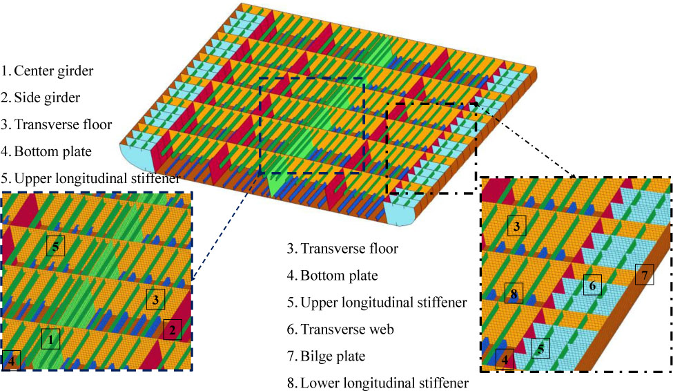
Geometry of the double bottom. The numbers highlight structural members on the model
Properties of the marine steel
| Material properties | Value | Material properties | Value |
|---|---|---|---|
| ρ | 7850 kg·m−3 | n | 0 |
| Ex | 210000 MPa | CS − C [38,39,40] | 3200 s−1 |
| v | 0.3 | CS − p [38,39,40] | 5 |
| σY | 315 MPa | ɛf | 0.2 |
The recommended strain by researchers [35,36,37] is in the range of 0.2–0.35; 0.2 was used in this analysis. Material sensitivity was inputted as a material characteristic using the Cowper-Symonds (CS) parameters. The large value of the Cowper-Symonds parameter C was chosen, as massive damage was expected to occur during the impact between the ship and obstruction. Kinematic hardening was assumed for the material by applying a zero value to the kinematic exponent.
In this work, the material and the structure were expected to experience massive damage due to the impact between the ship and seabed. In this situation, the material surpasses the maximum strain value and reaches the failure point at the end of the impact. Furthermore, it is essential to define the failure criterion in order to include the described concept in the finite element analysis. This work adopted the failure criterion introduced by Germanischer Lloyd (GL); the mathematical expression of this criterion is presented in Eq. (23) [41,42,43], which was initially introduced by Lehmann and Peschmann after a series of experimental works was carried out to observe energy absorption phenomena by steel structures in the event of ship collisions [44].
Here, ɛg is the uniform strain, ɛe is the necking strain, t is the plate thickness, and le is the individual element length.
4.3 Configuration of seabed topology
The obstruction refers to the conical indenter applied in a precious actual grounding test. Simplification of the geometry is still considered reliable for producing grounding damage. Since data of seabed topology are still limited, many researchers have used the high-profile grounding incident involving the Exxon Valdez in Alaska. Configuration of the obstruction geometry based on Zilakos et al. [45] and Prabowo et al. [46] is presented in Figure 6. The material properties of the pyroxene mineral were added to the geometry. This mineral was included as it is involved in oceanic crustal formation and is one of the hardest rock types. To maintain the solid characteristic, the obstruction was modelled as a rigid body which ensured that the absorbed strain energy and deformation were experienced by the thin-walled double bottom structure. The material definition for the obstruction and its displacement constraint are displayed in Table 3.
![Figure 6 Technical drawing of the rock geometry/conical obstruction. The illustration was made based on descriptions in [45, 46]](/document/doi/10.1515/jmbm-2021-0016/asset/graphic/j_jmbm-2021-0016_fig_006.jpg)
Material model and geometrical constraint of the pyroxene
| Material properties – parameters | Value – description |
|---|---|
| ρ | 4002 kg·m−3 |
| E | 147000 MPa |
| n | 0.281 |
| U constraint | Y and Z directions |
| R constraint | All directions |
4.4 Description of a grounding scenario
In a ship grounding, contact is defined between the ship structure and the obstruction. Fundamental case bottom raking was adopted as a reference to define the scenario configuration. During raking, the bottom structure was set to be fixed on the centerline. Both axial and rotational displacements were restrained, while these constraints were applied to the end of the inner bottom, bilge and bottom shells. As indicated in the configuration, the obstruction was to be freed for its axial displacement in longitudinal directions (x-axis in the Cartesian coordinate system). The uniform velocity Vu = 10 m·s−1 was to be applied to the obstruction so that it approached the structure during the grounding. An illustration of the grounding analysis in the current work is shown in Figure 7. It is shown that within crash simulations of various subjects in the automotive manufacturing industry, the adopted element length was usually in ranges 5–10 times larger than the shell/plate or subject thicknesses. In order to observe the significance of these numerical parameters in nonlinear problems, a series of mesh size variations was applied to the geometric models. A mesh size was determined based on the maximum Element Length-to-Thickness (ELT) ratio, with a value of 10 used, and the other sizes were one set of the expanded mesh sizes; three applied sizes had ratios in the range of 11–13. The influence of larger mesh sizes on the crashworthiness parameters, such as energy, force, acceleration and the damage pattern, were evaluated together with the progressive failure sequences. The possibility of expanding the current ratio ranges exists if larger mesh sizes produce a good similarity with the results of the recommended size, and further consideration of matching the reliable output within the optimum simulation time is summarized in the discussion.
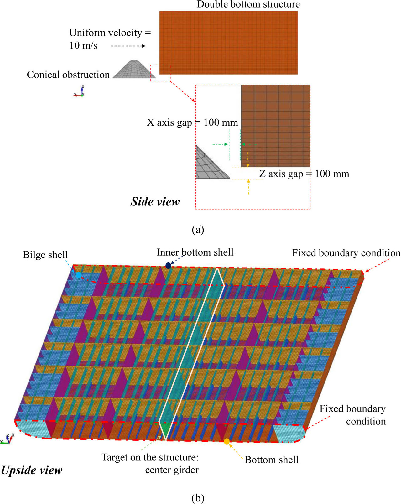
Grounding scenario adopted from the raking case: (a) gap configuration of two entities and (b) location of the applied boundary condition and target member on the double bottom structure
5 Crashworthiness parameters of the steel plated structure
5.1 Internal energy
Evaluation of the structural performance, accounting for elemental discretions, was undertaken by observing the energy criterion during grounding. The internal energy for the various mesh sizes is summarized in Figure 8. The results indicated that the mesh size of 132 mm with an ELT ratio of 11 produced a similar energy tendency to the recommended ELT ratio of 10. The difference of these sizes was concluded to be less than 1.8%. Incremental adjustments to the mesh size caused quite a high distinction when the ratio of 12 was applied to the geometric model. After surpassing the ratio of 12, the energy tendency of the ratio of 13 showed little difference, and tended to be very similar. A comparison of the end of the displacement distance concluded that the value differed by 0.1%. The notable differences in this criterion were compared with the tendency of the force criterion.
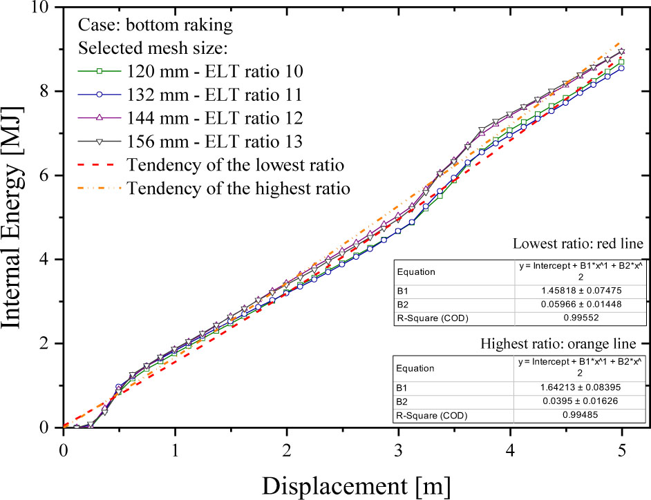
Results of the internal energy for various applied mesh sizes. Notable differences were observed in the transition from a mesh size of 132 mm (ELT ratio of 11) to 144 mm (ELT ratio of 12)
5.2 Crushing failure and progressive failure
Progressive failures on the structure were successfully summarized by presenting the results of the acting forces, denoted as the crushing force (see Figure 9). It was obtained in the early contact between the ship and the obstruction; a high amount of force occurred as the first local deformation on the structure. Advanced displacement of the obstruction on the structure made a breach on the transverse floor, and the force gradually reduced as a tearing opening on the bottom shell formed. Fluctuations of the force indicated that the steel was in a stable state with no significant increments during penetration occurring on the space between the two transverse floors. The next fluctuation appeared when the second floor started experiencing fractures. Based on these tendencies, the structural characteristics related to the first and second floors could be stated. The connections were composed of the longitudinal (center girder) and transverse (floor) members, and they were evidenced as capable of providing the highest resistance against the impact load. However, significantly, the meshes could not be clearly compared with each other, which led to more detailed observations on the specific acting force per the Cartesian axes.
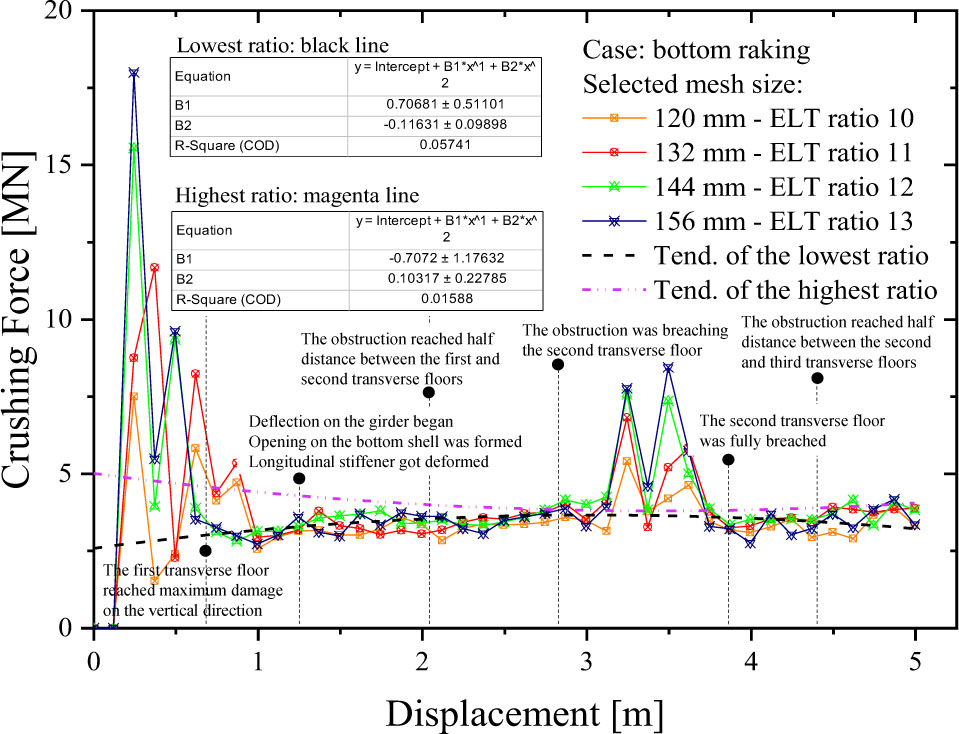
Progressive structural failure on the double bottom during accidental grounding process
The tendency of the longitudinal direction (Figure 10) indicated that the acting force in-line with the grounding direction produced a good similarity for all mesh sizes. These trends also provided an estimation that the damage of all mesh sizes on the same direction as the grounding had a similar pattern. High fluctuations were also recorded in the breaching event of the second transverse floor, which approximately occurred in the displacement range of 3–4 m. A detailed explanation regarding this matter will be presented in the damage discussion. The next observation looked at the transversal direction, as presented in Figure 11. The patterns indicated that similarity was noted in the high fluctuation regions or during early contact between the ship and the obstruction. Fluctuations for the mesh size of 120 mm were considered to be similar to the mesh size of 132 mm (ELT ratios of 10 and 11, respectively), while the mesh sizes of 144 and 156 mm provided a good correlation. High fluctuation during early contact suggested the center girder became heavily deformed, while the girder connections on the transverse floor and bottom shell were broken by the obstruction. Compared to the longitudinal direction, the acting forces on the Y-axis produced less fluctuations, even during the second transverse floor breach. Similar fluctuations of all mesh sizes were also observed after the tearing damage progressed to the bottom shell.
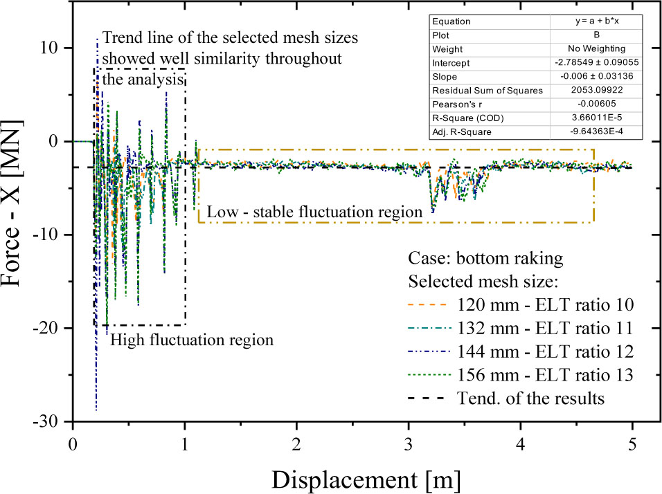
Trend line of the crushing force on the longitudinal (X) direction
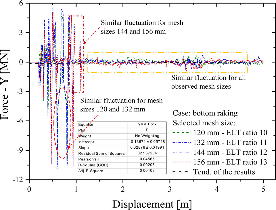
Trend line of the crushing force on the transversal (Y) direction
Verification of the similarity of the y-axis was conducted through observation of the acting force on the vertical direction (Figure 12). The mesh size of 120 mm was shown to match with the trend line of the mesh size of 132 mm in the displacement range of 0–1 m. In the same range, the mesh size of 144 mm also showed a similar pattern when compared to the 156 mm mesh size during the early crushing process. A quite high increment was also seen during the breaching of the second floor. The conical geometry and gap configuration of the grounding analysis were indicated as the causes, which led to further predictions that a steeper geometry and deeper penetration will cause higher fluctuations in the Y-force. Evaluation of the crushing force concluded that the results, in terms of the internal energy, were successfully verified by the tendency of the force criterion. To obtain clear confirmation, observations should be conducted based on the acting force on an individual direction. Specifically, the similarities can be spotted from initial contact until the first transverse floor was fully breached.
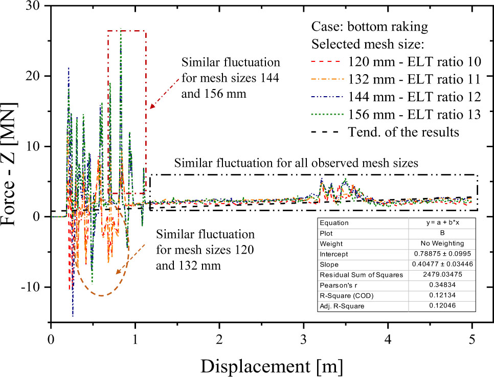
Trend line of the crushing force on the vertical (Z) direction
5.3 Crushing pattern and stress-strain contour
Structural damage on the double bottom was evaluated by comparing the stress and strain contours, as presented in Figures 13 and 14, respectively. It was observed that the critical stress of the mesh sizes of 120 and 132 mm occurred on the girder near the third transverse floor (see Figures 13a and 13b). Larger mesh sizes indicated a wider expansion of the stress intensity on the bottom shell, whose damage pattern also started to differ with the occurrence of the folding pattern for the mesh size of 144 mm (Figure 13c) and wider tearing on the most coarse mesh size of 156 mm (Figure 13d). It can be concluded that the coarser the applied mesh on the deformable structure, the faster the failure and deletion of damaged elements. Furthermore, the extent of damage on the coarse element was more widely distributed and more likely to leave a high failure mark on the residual element. This statement was verified by the strain contours of the impacted structures, using the mesh sizes of 144 and 156 mm (see Figures 14c and 14d); high strain contours were left on the center girder after the ship grounding. In contrast with this tendency, no high strain contour was observed for the smaller element sizes, i.e., the 120 and 132 mm mesh sizes (Figures 14a and 14b, consecutively).
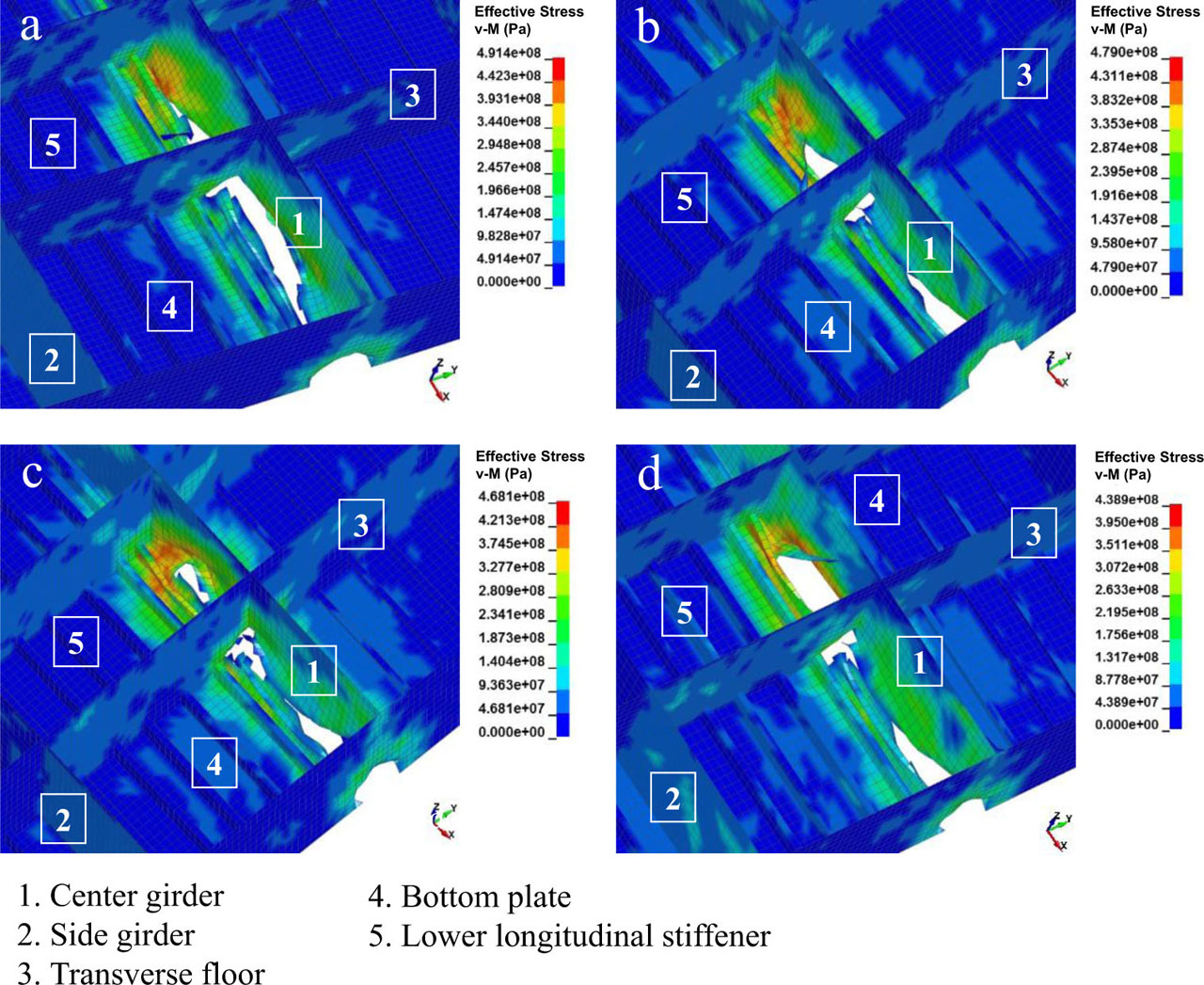
Stress contours using the von Mises (v-M) criterion on different mesh sizes: (a) 120 mm, (b) 132 mm, (c) 144 mm, and (d) 156 mm
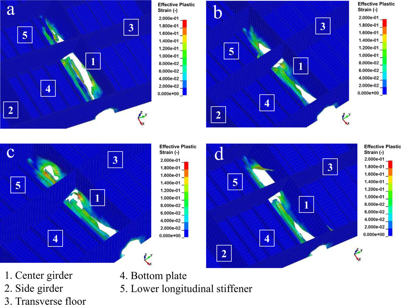
Strain contours (effective plastic strain) after the steel-plated structure was grounded on different meshes: (a) 120 mm, (b) 132 mm, (c) 144 mm, and (d) 156 mm
5.4 Structural acceleration
The final observed parameter was the structural acceleration. Effects of the mesh size were also found on this criterion, which indicated that the larger mesh size was capable of producing a higher maximum value during the grounding analysis. It was found that the incremental value reached 10 m/s2 in the comparisons between the recommended mesh (Figure 15a) and the other larger sizes (Figure 15b–15d).
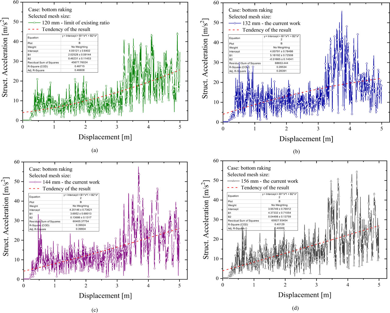
Acceleration of the double bottom: (a) 120 mm, (b) 132 mm, (c) 144 mm and (d) 156 mm
Considering the results of the expanded mesh sizes, most of the acceleration increments occurred when the second transverse floor was breached, and these became less significant when a mesh larger than 144 mm was applied to the structures. Higher crashworthiness parameters were successfully confirmed based on these results, and the characteristic of the damage contours was identified.
5.5 Remarks on mesh influence
The advantage of applying large mesh sizes is that less simulation time is needed. This statement is verified by the simulation time of the current work, as shown in Table 4. The recommended mesh, as selected as the smallest mesh, produced the most expensive time, with more than 4000 s recorded for one simulation. Application of a larger mesh size of 132 mm was observed as capable of reducing the simulation time by approximately 45%. Irregularities occurred in the simulation with the mesh size of 144 mm – the larger element needed more processing time to produce a solution. Further, it was not a normal tendency; the difference was also smaller than the previous tendency, with a value of 11% compared to the 132 mm mesh size recorded. The difference in simulation time was back to around 45% when the applied mesh selected was 156 mm.
6 Concluding remarks
A series of theoretical contact formulations were discussed in this work as the visualization of a ship grounding involving two entities in an impact phenomenon. The grounding was then classified to adopt raking as being representative of the contact as well as of the impact on the maritime environment. In the next stage, numerical evaluation of the steel-plated structure under a raking incident between the bottom part of a double-hulled tanker and seabed rock was performed. In this work, the influence of the defined geometrical mesh size in the FE assessment on the structural crashworthiness parameters was evaluated. Several parameters, including internal energy, crushing force, progressive failure, damage contour, and acceleration were used to evaluate nonlinear phenomena of the structure conditions. The comparative results of the initial internal energy revealed a significant difference between the mesh sizes of 132 and 144 mm (based on calculation of the ELT ratio). Moreover, confirmation of the internal energy was not achievable in the presence of the crushing force, but the criteria were deemed adequate for presenting the progressive structural collapse in a grounding incident. The assessment was broadened to include more precise criteria, such as the acting force on the transverse and vertical directions. Similarities in the internal energy were successfully detected in forces at those directions, which occurred during the initial failure or when the tearing opening on the bottom shell occurred. As increasingly coarse elements were added to the numerical geometry, the contours of stress and strain indicated a larger expansion and greater strain level on the residual element after grounding. Higher levels on higher mesh sizes were also verified by an increase in the structural acceleration of roughly 17%.
Funding information:
This work was supported by the RKAT PTNBH Universitas Sebelas Maret, Surakarta, under the scheme “Penelitian Kolaborasi Internasional UNS” (KI-UNS) 2021, with grant/contract number 260/UN27.22/HK.07.00/2021. The support is gratefully acknowledged by the authors.
Author contributions:
All authors have accepted responsibility for the entire content of this manuscript and approved its submission.
Conflict of interest:
The authors state no conflict of interest.
References
[1] Allianz. Safety and shipping 1912–2012, From Titanic to Costa Concordia. Allianz Global Corporate & Specialty; 2012.Search in Google Scholar
[2] Paik JK. Quantitative Grounding Risk Assessment and Management. In: Paik JK, editor. Advanced Structural Safety Studies. Singapore: Springer; 2020. p. 475–506.10.1007/978-981-13-8245-1_15Search in Google Scholar
[3] Wright RG, Baldauf M. Arctic Environment Preservation through Grounding Avoidance. In: Hildebrand LP, Brigham LW, Johansson TM, editors. Sustainable Shipping in a Changing Arctic; Springer, Cham. 2018. p. 75–98.10.1007/978-3-319-78425-0_5Search in Google Scholar
[4] Brubak L, Hu Z, Kõrgesaar M, Schipperen I, Tabri K. Numerical Simulations of Grounding Scenarios–Benchmark Study on Key Parameters in FEM Modelling; Proceedings of the 14th International Symposium on Practical Design of Ships and Other Floating Structures. 2019 Sep 22–26; Yokohama, Japan; 2019.10.1007/978-981-15-4672-3_16Search in Google Scholar
[5] Prabowo AR, Bae DM. Environmental risk of maritime territory subjected to accidental phenomena: Correlation of oil spill and ship grounding in the Exxon Valdez's case. Results in Eng. 2019;4:100035.10.1016/j.rineng.2019.100035Search in Google Scholar
[6] Ehlers S. A procedure to assess the Damage of a Grounded Ship: A Full-Scale Validation Case Study. Ship Technol Res. 2011;58:90–9.10.1179/str.2011.58.2.003Search in Google Scholar
[7] Bai Y, Bai Q. Chapter 15 - Marine Traffic Risk Assessment. In: Bai Y, Bai Q, editors. Subsea Pipeline Integrity and Risk Management 2014;331–43.10.1016/B978-0-12-394432-0.00015-9Search in Google Scholar
[8] Prabowo AR, Byeon JH, Cho HJ, Sohn JM, Bae DM, Cho JH. Impact phenomena assessment: Part I-Structural performance of a tanker subjected to ship grounding at the Arctic. MATEC Web Conf. 2018;159:02061.10.1051/matecconf/201815902061Search in Google Scholar
[9] Prabowo AR, Sohn. JM, Byeon. JH, Bae. DM, Zakki AF, Cao. B. Structural analysis for estimating damage behavior of double hull under ice-grounding scenario models. Key Eng Mater. 2017;754:303–06.10.4028/www.scientific.net/KEM.754.303Search in Google Scholar
[10] Paik. JK. Practical techniques for finite element modeling to simulate structural crashworthiness in ship collisions and grounding (Part I: Theory). Ships Offshore Struct. 2007;2:69–80.10.1533/saos.2006.0148Search in Google Scholar
[11] Villavicencio R, Liu B, Soares CG. Response of a tanker side panel punched by a knife indenter. Proceeding of Collision and Grounding of Ships and Offshore Structures; London, UK: Taylor and Francis, London; 2013.10.1201/b14915-14Search in Google Scholar
[12] Prabowo AR, Cao B, Sohn JM, Bae DM. Crashworthiness assessment of thin-walled double bottom tanker: Influences of seabed to structural damage and damage-energy formulae for grounding damage calculations. J of Ocean Eng and Sci. 2020;5:387–400.10.1016/j.joes.2020.03.002Search in Google Scholar
[13] Prabowo AR, Bahatmaka A, Sohn JM. Crashworthiness characteristic of longitudinal deck structures against identified accidental action in marine environment: a study case of ship–bow collision. J Braz Soc Mech Sci Eng. 2020;42:584.10.1007/s40430-020-02662-2Search in Google Scholar
[14] Kõrgesaar M, Romanoff J, Remes H. Influence of material nonlinearity on load carrying mechanism and strain path in stiffened panel. Procedia Struct Integrity. 2017;5:713–20.10.1016/j.prostr.2017.07.050Search in Google Scholar
[15] Heinvee M, Tabri K. A simplified method to predict grounding damage of double bottom tankers. Mar Struct. 2015;43:22–43.10.1016/j.marstruc.2015.04.002Search in Google Scholar
[16] Sun B, Hu Z, Wang J. Bottom structural response prediction for ship-powered grounding over rock-type seabed obstructions. Mar Struct. 2017;54:127–43.10.1016/j.marstruc.2017.04.002Search in Google Scholar
[17] Liu Z, Amdahl J. A new formulation of the impact mechanics of ship collisions and its application to a ship–iceberg collision. Mar Struct. 2010;23:360–84.10.1016/j.marstruc.2010.05.003Search in Google Scholar
[18] Yu Z, Hu Z, Amdahl J, Liu Y. Investigation on structural performance predictions of double-bottom tankers during shoal grounding accidents. Mar Struct. 2013;33:188–213.10.1016/j.marstruc.2013.06.003Search in Google Scholar
[19] Park DK, Kim DK, Seo JK, Kim BJ, Ha YC, Paik JK. Operability of non-ice class aged ships in the Arctic Ocean-part II: Accidental limit state approach. Ocean Eng. 2015;102:206–15.10.1016/j.oceaneng.2015.04.038Search in Google Scholar
[20] Prabowo AR, Laksono FB, Sohn JM. Investigation of structural performance subjected to impact loading using finite element approach: Case of ship-container collision. Curved Layer Struct. 2020;7:17–28.10.1515/cls-2020-0002Search in Google Scholar
[21] Stronge WJ. Impact mechanics. Cambridge: Cambridge University Press; 2004.10.1017/S2753906700000802Search in Google Scholar
[22] Prabowo AR, Putranto T, Sohn JM. Comparing structural casualties of the Ro-Ro vessel using straight and oblique collision incidents on the car deck. J Mar Sci Eng. 2019;7:183.10.3390/jmse7060183Search in Google Scholar
[23] Oshiro RE, Calle MAG, Mazzariol LM, Alves M. Experimental study of collision in scaled naval structures. Int J Impact Eng. 2017;103:149–61.10.1016/j.ijimpeng.2017.01.024Search in Google Scholar
[24] Ridwan R, Prabowo AR, Muhayat N, Putranto T, Sohn JM. Tensile analysis and assessment of carbon and alloy steels using fe approach as an idealization of material fractures under collision and grounding. Curved Layer Struct. 2020;7:188–98.10.1515/cls-2020-0016Search in Google Scholar
[25] Calle MAG, Oshiro RE, Alves M. Ship collision and grounding: Scaled experiments and numerical analysis. Int J Impact Eng. 2017;103:195–210.10.1016/j.ijimpeng.2017.01.021Search in Google Scholar
[26] Zhang S, Villavicencio R, Zhu L, Pedersen PT. Ship collision damage assessment and validation with experiments and numerical simulations. Mar Struct. 2019;63:239–56.10.1016/j.marstruc.2018.09.005Search in Google Scholar
[27] Prabowo AR, Cahyono SI, Sohn JM. Crashworthiness assessment of thin-walled double bottom tanker: A variety of ship grounding incidents. Theor App Mech Lett. 2019;9:320–7.10.1016/j.taml.2019.05.002Search in Google Scholar
[28] Prabowo AR, Sohn JM, Bae DM, Setiyawan A. Crashworthiness assessment of thin-walled bottom structures during powered-hard grounding accidents. Proceedings of the International Conference on Offshore Mechanics and Arctic Engineering – OMAE; 2018 June 17–22; Madrid, Spain.10.1115/OMAE2018-77492Search in Google Scholar
[29] Bathe KJ. Finite element procedures. New Jersey: Prentice-Hall Inc; 1996.Search in Google Scholar
[30] ANSYS. ANSYS LS-DYNA user's guide. Pennsylvania: ANSYS Inc; 2017.Search in Google Scholar
[31] Alsos HS, Amdahl J. On the resistance to penetration of stiffened plates, Part I – Experiments. Int J Impact Eng. 2009;36:799–807.10.1016/j.ijimpeng.2008.10.005Search in Google Scholar
[32] Alsos HS, Amdahl J, Hopperstad OS. On the resistance to penetration of stiffened plates, Part II: Numerical analysis. Int J Impact Eng. 2009;36:875–87.10.1016/j.ijimpeng.2008.11.004Search in Google Scholar
[33] AbuBakar A, Dow RS. Simulation of ship grounding damage using the finite element method. Int J Sol Struct. 2013;50:623–36.10.1016/j.ijsolstr.2012.10.016Search in Google Scholar
[34] ANSYS. ANSYS mechanical APDL element reference. Pennsylvania: ANSYS Inc; 2017.Search in Google Scholar
[35] Amdahl J, Kavlie D. Experimental and numerical simulation of double hull stranding. DNV-MIT Work Shop on Mechanics of Ship Collision and Grounding. Oslo; 1992.Search in Google Scholar
[36] Wen HM, Jones N. Experimental investigation of the scaling laws for metal plates struck by large masses. Int J Impact Eng. 1993;13:485–505.10.1016/0734-743X(93)90120-VSearch in Google Scholar
[37] Zhang S. The mechanics of ship collision. Lyngby: Technical University of Denmark; 1999.Search in Google Scholar
[38] Lim HK, Lee JS. On the structural behavior of ship's shell structures due to impact loading. Int J Naval Arch Ocean Eng. 2018;10:103–18.10.1016/j.ijnaoe.2017.03.002Search in Google Scholar
[39] Jones N. Structural impact. New York: Cambridge University Press; 2012.Search in Google Scholar
[40] Storheim M, Amdahl J. On the sensitivity to work hardening and strain-rate effects in nonlinear FEM analysis of ship collisions. Ships Offshore Struct. 2017;12:100–15.10.1080/17445302.2015.1115181Search in Google Scholar
[41] Ozguc O, Das PK, Barltrop N. A comparative study on the structural integrity of single and double side skin bulk carriers under collision damage. Mar Struct. 2005;18:511–47.10.1016/j.marstruc.2006.01.004Search in Google Scholar
[42] Calle MAG, Verleysen P, Alves M. Benchmark study of failure criteria for ship collision modeling using purpose-designed tensile specimen geometries. Mar Struct. 2017;53:68–85.10.1016/j.marstruc.2017.01.001Search in Google Scholar
[43] Prabowo AR, Baek SJ, Byeon JH, Bae DM, Cho JH, Sohn JM. Investigation on the Structural Damage of a Double-Hull Ship, Part I – Ship Collision. Proc Struct Inetg. 2017;5:935–42.10.1016/j.prostr.2017.07.126Search in Google Scholar
[44] Lehmann E, Peschmann J. Energy absorption by the steel structure of ships in the event of collisions. Mar Struc. 2002;15:429–41.10.1016/S0951-8339(02)00011-4Search in Google Scholar
[45] Zilakos M, Toulios M, Nguyen TH, Samuelides M, Amdahl J. Simulation of the response of double bottoms under grounding actions using finite elements. In: Soares CG, Das PK, editors. Analysis and Design of Marine Structures. London: Taylor and Francis; 2009.Search in Google Scholar
[46] Prabowo AR, Putranto T, Sohn JM. Simulation of the Behavior of a Ship Hull under Grounding: Effect of Applied Element Size on Structural Crashworthiness. J Mar Sci Eng. 2019;7:270.10.3390/jmse7080270Search in Google Scholar
[47] Törnqvist R. Design of crashworthy ship structures. Lyngby: Technical University of Denmark; 2003.Search in Google Scholar
[48] Alsos HS, Amdahl J. On the resistance of tanker bottom structures during stranding. Mar Struct. 2007;20:218–37.10.1016/j.marstruc.2007.06.001Search in Google Scholar
[49] Tornqvist R, Simonsen BC. Safety and structural crashworthiness of ship structures Modelling tools and application in design. Proceedings of The third International Conference on Collision And Grounding of Ships; 2004; Izu, Japan.Search in Google Scholar
[50] Hogström P. RoPax ship collision - a methodology for survivability analysis. Gothenburg: Chalmers University of Technology; 2012.Search in Google Scholar
[51] Kõrgesaar M. Modeling ductile fracture in ship structures with shell element. Helsinki: Aalto University; 2015.Search in Google Scholar
[52] Obisesan A, Sriramula S, Harrigan J. A framework for reliability assessment of ship hull damage under ship bow impact. Ships Offshore Struct. 2016;11:700–19.10.1080/17445302.2015.1051281Search in Google Scholar
[53] Fan W, Yuan W. Ship bow force-deformation curves for ship-impact demand of bridges considering effect of pile-cap depth. Shock Vib. 2014;201425.10.1155/2014/201425Search in Google Scholar
© 2021 Aditya Rio Prabowo et al., published by De Gruyter
This work is licensed under the Creative Commons Attribution 4.0 International License.
Articles in the same Issue
- Research Articles
- The elastic-plastic properties of an anti-icing coating on an aluminum alloy: Experimental and numerical approach
- Optimization of recycled slag-fresh flux mixture based upon weld bead quality for submerged arc welding of stainless steel
- Design and optimization of differential capacitive micro accelerometer for vibration measurement
- Mechanical performance of abrasive sandpaper made with palm kernel shells and coconut shells
- Experimental investigation of WEDM process through integrated desirability and machine learning technique on implant material
- Mechanical properties and microstructural characteristics of rotating arc-gas metal arc welded carbon steel joints
- Assessment of cement replacement with fine recycled rubber particles in sustainable cementitious composites
- Structural response and sensitivity analysis of granular and asphaltic overlayment track considering linear viscoelastic behavior of asphalt
- Unmanned aerial vehicle evasion manoeuvres from enemy aircraft attack
- Effect of corrosion on surface degradation of galvanized steel in poultry dung, pig dung and urea solutions using rice straw as an inhibitor
- Mathematical modeling of AZ30 magnesium alloys at high temperature using the ring compression test and genetic algorithm method
- Study on hot deformation behavior and workability of stir-cast Al6063-6wt.% steelp based composites
- The effects of processing parameters on the formation of oxide layers in aluminium alloys using plasma electrolytic oxidation technique
- Behavior of green reactive powder mortar reinforced with steel fibers
- On the hygrothermal properties of sandcrete blocks produced with sawdust as partial replacement of sand
- Mechanical behavior of thin-walled steel under hard contact with rigid seabed rock: Theoretical contact approach and nonlinear FE calculation
- Mechanical properties and microstructural characteristics of rotary friction welded dissimilar joints of rolled homogeneous armor steel and medium carbon steel
- Studies of carboxylated nitrile butadiene rubber/butyl reclaimed rubber (XNBR/BRR) blends for shoe soles application
- Mechanical properties of wire arc additive manufactured carbon steel cylindrical component made by gas metal arc welding process
- Synthesis and mechanical characterization of Si3N4 reinforced copper-tin matrix composites
- Analysis of plated-hull structure strength against hydrostatic and hydrodynamic loads: A case study of 600 TEU container ships
- Mechanical performance investigation of lignocellulosic coconut and pomegranate / LDPE biocomposite green materials
- Special Issue MICAP-2021
- Double hydrothermal synthesis of iron oxide/silver oxide nanocomposites with antibacterial activity**
- Enhanced photocatalytic activity of TiO2-CdS composite nanofibers under sunlight irradiation**
- Structural properties of CoxCu1−xFe2O4 solid solution**
- Green-synthesis of Ag2O nanoparticles for antimicrobial assays**
- Effect of current density on the porous silicon preparation as gas sensors**
- A mechanochemical preparation, properties and kinetic study of kaolin–N, P fertilizers for agricultural applications**
- Impact strength of surface treated SS316L wires reinforced PMMA**
- Computational studies on electronic and optical properties of dopamine derivatives structure: A DFT study**
- Multilayer coating effects on the thermal conductivity of tools using an electric furnace technique**
- The positron and mechanical parameters of a cold-worked aluminum alloy (3004) Using PALT, PADBT and HV**
- Effect of thermal annealing on the structural and optical properties of TiO2 nanostructures**
- Improvement of forging die life by failure mechanism analysis**