Optimization of recycled slag-fresh flux mixture based upon weld bead quality for submerged arc welding of stainless steel
-
Sandeep Jindal
 and
Harpreet Singh
and
Harpreet Singh

Abstract
Submerged arc welding (SAW) has been performed using slag-fresh flux mixture on duplex stainless steel plates. Experiments were performed by recycled slag-fresh flux mixtures with iron powder; iron powder is mixed to maintain and enhance the weld strength. The effect of composition variation of slag-fresh flux mixture on weld bead geometry parameters have been investigated quantitatively. Weld bead characteristics viz. bead width; bead height; penetration area; reinforcement area, form factor and dilution were observed by metallography operations for each experiment. For varying the composition of slag-fresh flux mixture, mixture design technique; Scheffe Quadratic Model (SQM) was used. Empirical relations were developed for weld bead characteristics in terms of fresh flux, slag and iron powder and statistically checked for significance. Finally, recycled slag-fresh flux composition was optimized using desirability approach.
1 Introduction
In today's competitive manufacturing environment; maintaining product quality along with healthy environment at an optimal cost is a big challenge for the production engineers and researchers. Submerged arc welding (SAW) is advantageous as compared to other welding techniques owing to its excellent unmatched qualities like sound weld joints, good dilution, good surface finish, almost zero atmospheric contamination and perform welding in much thicker plates such as ship building, nuclear reactors, pressure vessels, structural applications. Out of the components of SAW, flux is the main component which maintains arc stability, mechanical and chemical properties of the weldment. During the SAW process granular flux helps in element transfer from welding pool to the base metal also isolating the molten pool from atmosphere thus protecting the weldment from contaminating gases in the atmosphere and finally forms a layer of slag on the weld bead. But along with above unmatched qualities SAW process produces large amounts of slag which is generally disposed on the earth [1], disposal of which become hazardous to our environment. Some researchers have suggested the recycling of the slag may be advantageous from cost cutting and environmental views. From years regardless of large amount of slag produced; very few research work could be found suggesting the scientifically developed methodology in recycling of slag. Datta et al. [2] used grey relational Taguchi technique for solving multi-criterion (objective) optimization based on welding parameters and flux-slag mixture in submerged arc welding (SAW) of mild steel plates. In the experiments fresh flux was mixed with slag to get five different flux-slag mixtures. Arc voltage, welding current, electrode stick out, wire feed and flux-slag mixtures were taken as process parameters. The work suggested that 10% flux-slag mixture may be taken as optimum mixture to obtain acceptable weld quality on the basis of bead geometry parameters.
Singh and Pandey [3] carried out experiments using recycled slag on C-Mn steel. Trials were conducted to check the chemical composition of the weld metal for C, Mn, Si, S, and P using different proportions of fresh flux and recycled slag such 100% recycled slag, 100% flux, mixed recycled slag then results were compared with the requirement according to American Welding Society (AWS) standards. Fluxes were generated by suitably mixing the fresh flux with slag and other components made with by agglomeration process. It was concluded that variation of chemical composition of weld metal with recycled slag from that with AWS standards falls within acceptable range.
Garg and Singh [4] in their work suggested that recycled flux may be reused causing replenishment of resources, preventing environmental contamination and decreasing the total cost of SAW process. Recycled flux were used for getting welds on stainless steel claddings. The chemical composition, bend test, microhardness test, Ferrite measurements, microstructure examination were performed on both types of claddings (recycled slag and pure flux); revealed that clad characteristics with recycled slag are of same quality as that of claddings produced with pure flux.
Annoni et al. [1] performed their study on characterization of SAW slags by various methods; X-ray fluorescence (XRF), X-ray diffraction (XRD), Raman spectroscopy and SEM analysis. The authors observed same Aluminium content in both neutral and acidic slags while that of Titanium content was found to be more in acidic slags than in neutral slags. The work also attempted to decrease Al and Ti content by leaching tests using three different techniques.
The bead geometry plays an important role in deciding weld quality in all the welding processes. Number of suggestions may be followed given by different authors such as bead geometry influences the weld strength, excessive bead width widens the heat affected area [5], less bead depth and more bead width provide resistance to cracking, dilution should be high i.e. penetration area should be maximum [6].
In work present here; slag was recycled to form bead on plate experiments on 150×100mm; 12mm thick duplex steel plates. Slag was mixed with fresh flux in addition to iron powder.
Seventeen recycled slag-flux mixtures were formulated using statistical mixture design Scheffé's method. Regression equations for weld bead characteristics have been formed in terms of slag, flux and iron powder. Finally, these characteristics have been optimized to get optimum slag-flux mixture composition.
2 Experimentation
2.1 Preparation of slag-flux mixture
In mixture experiments with more than two components mixed in various proportions and a number of responses are measured in terms of each mixture; Scheffe Quadratic Model (SQM) is the most frequently used design tool [7, 8] to generate mathematical models for output parameters in the form of the mixture components. SQM contains k linear terms βixi, and K = k(k − 1)/2 2nd order terms βijxixj(i < j). The output responses are represented in the form of quadratic model as:
Terms βixi and βijxixj in the quadratic model represent individual effect and binary effect of the mixture respectively.
In the work presented here, three components recycled slag, fresh flux and iron powder are taken as per the following constraints:
Slag was collected from a pipeline fabrication industry. Slag was then crushed, sieved and grain sizing was done. Then slag was mixed with fresh flux and iron powder. The addition of iron powder has been used not only for improving the productivity of SAW rather it prevents the base plate from wastefully melting due to high heat input of welding [9].
Seventeen recycled slag-flux mixtures were formulated using Scheffé's Design as per design matrix Table 1. Then slag-flux mixtures were kept in a furnace at 250°C for nearly 1 hour to remove any moisture picked up from atmosphere during mixing. After cooling, these mixtures were kept in air-tight bags for submerged arc welding.
DOE and results for weld bead characteristics
| Flux Mixture | Slag (Wt%) | Flux (Wt%) | Iron powder (Wt%) | Width mm | Height mm | RA mm2 | PA mm2 | FF | Dilution |
|---|---|---|---|---|---|---|---|---|---|
| 1 | 40 | 50 | 10 | 15 | 5.2 | 25.9 | 41.9 | 2.9 | 0.62 |
| 2 | 10 | 80 | 10 | 15.3 | 5.9 | 23.9 | 41.2 | 2.6 | 0.63 |
| 3 | 20 | 50 | 30 | 13.9 | 6.4 | 28.9 | 32.8 | 2.2 | 0.53 |
| 4 | 10 | 60 | 30 | 12.8 | 6.8 | 33.1 | 32.5 | 1.9 | 0.5 |
| 5 | 25 | 65 | 10 | 16.6 | 6.3 | 29.3 | 43.9 | 2.6 | 0.6 |
| 6 | 30 | 50 | 20 | 15.7 | 6.8 | 27.3 | 43 | 2.3 | 0.61 |
| 7 | 10 | 70 | 20 | 15.2 | 7.5 | 29.2 | 43.6 | 2 | 0.6 |
| 8 | 15 | 55 | 30 | 13.7 | 7 | 32.6 | 32.6 | 2 | 0.5 |
| 9 | 30 | 55 | 15 | 16.4 | 7.1 | 29.3 | 44.4 | 2.3 | 0.6 |
| 10 | 15 | 70 | 15 | 16.1 | 7.2 | 29.1 | 43.1 | 2.2 | 0.6 |
| 11 | 20 | 55 | 25 | 14.8 | 7.3 | 30.2 | 39.7 | 2 | 0.57 |
| 12 | 15 | 60 | 25 | 14.5 | 8.2 | 31.7 | 38.7 | 1.8 | 0.55 |
| 13 | 22.5 | 62.5 | 15 | 16.5 | 7.2 | 29.8 | 45.3 | 2.3 | 0.6 |
| 14 | 25 | 55 | 20 | 15.7 | 7.4 | 28.2 | 42.3 | 2.1 | 0.6 |
| 15 | 15 | 65 | 20 | 15.1 | 7.7 | 31.3 | 44.2 | 2 | 0.59 |
| 16 | 17.5 | 57.5 | 25 | 14.7 | 8.2 | 30.4 | 39.9 | 1.8 | 0.57 |
| 17 | 20 | 60 | 20 | 16.1 | 7.8 | 29.2 | 43.2 | 2.1 | 0.6 |
2.2 Bead on plate
For performing the bead on plate, the SS plates were squared up and cleaned to remove any grease, dirt and descaled to get defect free welds. Seventeen weld beads were formed on 12 mm thick duplex steel plates of dimensions 150×100 mm. Multi beads were taken limiting to two on each plate to keep the after-weld plate distortion free. Weld beads were formed using 3.2 mm diameter electrode wire with DCEP keeping nozzle to work distance at 22mm on welding setup (Torando SAW M-800) at MM(DU), Mullana (Ambala). During welding input parameters were kept constant at welding current 425A, voltage 34 V, travel speed 22 m/hr keeping the wire feed rate constant with constant voltage mode. The constant values of welding parameters; welding current, voltage, travel speed by performing the trials runs using the welding current 330–600A, welding voltage 26–34V and weld speed 17 to 33 m/h.
Chemical composition of base metal and welding wire is shown in Table 2 and Table 3.
Chemical composition of base plate
| C | Mn | Cr | Ni | Mo |
|---|---|---|---|---|
| 0.04 | 2.00 | 22.4 | 5.1 | 2.9 |
Chemical composition of welding wire
| C | Mn | Si | Cr | Ni | Mo |
|---|---|---|---|---|---|
| 0.01% | 1.5% | 0.5% | 20.6% | 8.6% | 3.1% |
2.3 Measurement of responses
Weld bead characteristics were measured using polishing operations and then etching with 5% nitric acid-ethanol solution. The weld bead geometry characteristics (Refer Figure 1); namely bead width (W), bead height (h), reinforcement area (RA) and penetration area (PA) were measured. The weld bead property form factor is also calculated which is the ratio of weld bead width to the weld bead height. In the present work the recycled flux mixture have been optimized using the form factor value at 1.5. The value of form factor (1.5) has been taken as per the guidelines issued in the literature Welding Handbook: AWS i.e., wide width and shallow depth have maximum resistance to centreline cracking [10]. Actual bead profiles after polishing and etching operations are shown in Figure 1.
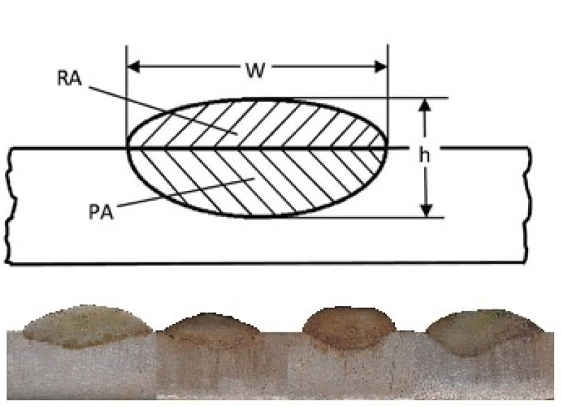
Bead profile indicating different bead characteristics and macrograph of actual bead profile
W - width, h - height, RA - reinforcement area, PA - penetration area
3 Results
Results of the weld bead characteristics; width, height, reinforcement area (RA), penetration area (PA), form factor (FF) and dilution have been indicated in Table 1.
3.1 Mathematical models for weld bead characteristics
Scheffe Quadratic Model/Equations (SQM) have been formed in terms of percentage composition of slag, flux and iron powder from the experimentally determined values of weld bead characteristics. SQM have been developed in terms of individual effect of slag, flux and iron powder and their interaction/binary mixtures (Slag×Flux, Slag×Iron Powder, Flux×Iron Powder) represented as Eq. (6), (7), (8), (9), (10), (11).
3.2 Significance testing of models
SQ Models (6), (7), (8), (9), (10), (11) were analyzed using t-test and ANOVA. Individual regression coefficients (βi and βj) have been tested for significance by comparing experimental t-value with tabulated t value (at 95% confidence and dof of error) [8, 11] are given in appendix 1. Degrees of freedom (doferror) are the number of independent values that a statistical analysis can estimate. Complete SQ model tested for significance by F-test and Probability value (p-value) at 95% of confidence level. R-square values for all of the regression models are within acceptable range which is more than 90% for all models. R-square value estimates the relationship of the predicted values with the response variable (Represented in Table A2 in appendix 1).
4 Discussion
4.1 Effect of mixture constituents on bead properties
It can be observed from results that bead width decreases with slag and iron powder whereas flux and all other binary mixtures tend to increase the width. Both individual and binary mixtures have significant effect on the width. Increase of slag and iron powder to the slag-flux mixture may hinder the transfer of elements from electrode wire and base metal to the weld pool which may restrict the widening of weld cone. Also, more slag may decrease the fluidity of the molten pool which may restrict the flow of weld pool. In contrary to this; increase in flux component may increase weld pool fluidity and transfer of elements thereby increasing width. Same phenomena may be applied for increase in width due to binary mixtures.
Bead height tend to decrease with increase in composition of all the individual mixtures; slag, flux and iron powder but all binary mixtures increase height significantly with confidence level of 95%. With the addition of flux and other elements; the fluidity of the weld pool increase; but there will be decrease in bead height due to corresponding increase in bead width.
Summary table indicates that individual mixtures imply similar effect on reinforcement area and penetration area. Slag tend to decrease reinforcement area and penetration area of weld bead but exactly opposite effect is being observed with increase of flux constituent. As discussed in the previous section that penetration area should be large as compared to reinforcement area for dilution to be high. Also, the previous sections indicate that increase in flux component increases bead volume which affects increase in the penetration area as well as reinforcement area. Similar opposite effects of slag and iron powder addition may be explained in the same manner. All the binary mixtures show synergism effect on both bead characteristics reinforcement area and penetration area except slag-iron mixture which shows antagonism effect on area of reinforcement.
Summary of effect of individual and binary mixtures indicates that all the individual mixtures tend to increase the form factor whereas all the binary mixtures have antagonism effect on the form factor. Form factor is the ratio of bead width to the bead height and depends on the relative values of width and height. Phenomenon for increase or decrease of bead height and bead width is already explained in previous sections. In the same manner dilution is calculated from the reinforcement area and penetration area; discussion regarding variation of both weld geometry characteristics with individual mixtures and binary mixtures have already been done in the past sections. Increase in dilution is due to much decrease in reinforcement area than penetration area and vice versa.
4.2 Contour graphs for bead characteristics
Contour surface plot [12] shows variation of output characteristics with respect to individual constituents in a mixture hence any line indicated on the graph gives constant value of that characteristics and any point on graph represents possible mixture. Figure 2 shows contour surface plots for weld bead geometry characteristics; bead width, bead height, penetration area, reinforcement area, form factor and dilution for different flux compositions.

Contour surface plots for bead width, bead height, penetration area, reinforcement area, form factor and dilution
5 XRD analysis of slag
X-ray diffraction (XRD) analysis of powdered slag samples was also done to check elemental pickup during submerged arc welding. Slag samples were collected after the welding was performed in each recycled fluxes then screened to 250 μm size approximately. Powdered slag samples specimens were analyzed for XRD in diffractometer with a monochromatic Cu-Kα radiation with 2α degree (in the range from 10° to 110°). The X-ray diffraction patterns of slag samples 5 have been represented in Figure 3. XRD raw files have been analyzed in PANalytical X’Pert HighScore Plus software and Origin software. Some common phases have been observed in the slag samples which are generally crystalline compounds found in the previous literature [13, 14, 15] such as
Gehlenite (Calcium Magnesium Aluminum Silicate, Ca2(Mg0.25Al0.75)(Si1.25Al0.75O7)),
Calcium Magnesium Aluminum Silicate Chloride, (Ca19.44Mg2.56)(Si0.75Al0.25)8O36Cl2,
Tinaksite,
K2.06Ti0.95Ca1.85 Na0.98Fe0.11Mn0.11Mg0.02Si7O18(OH),
Rosenbuschite,
Ca7Na5Zr2(TiMn)(Si2O7)4O2F4O2H3,
Clinopyroxene,
(Al0.058Fe0.132Mg0.734Ti0.073Cr0.003)
(Ca0.569Fe0.231Mg0.183Mn0.017)(Si1.792Al0.208O6),
Giannettite,
(Na2Ca(TiO(OH)(Si2O7)2))Ca3(Ca0.7Mn0.1Fe0.1Ce0.1)F2,
Calcium Magnesium Silicate,
Mg3.90Ca0.10(SiO3)4,
Anorthite,
Ca(Al2Si2O8),
Zeolite,
Ca40.32(Al96Si96O384)(H2O)32.
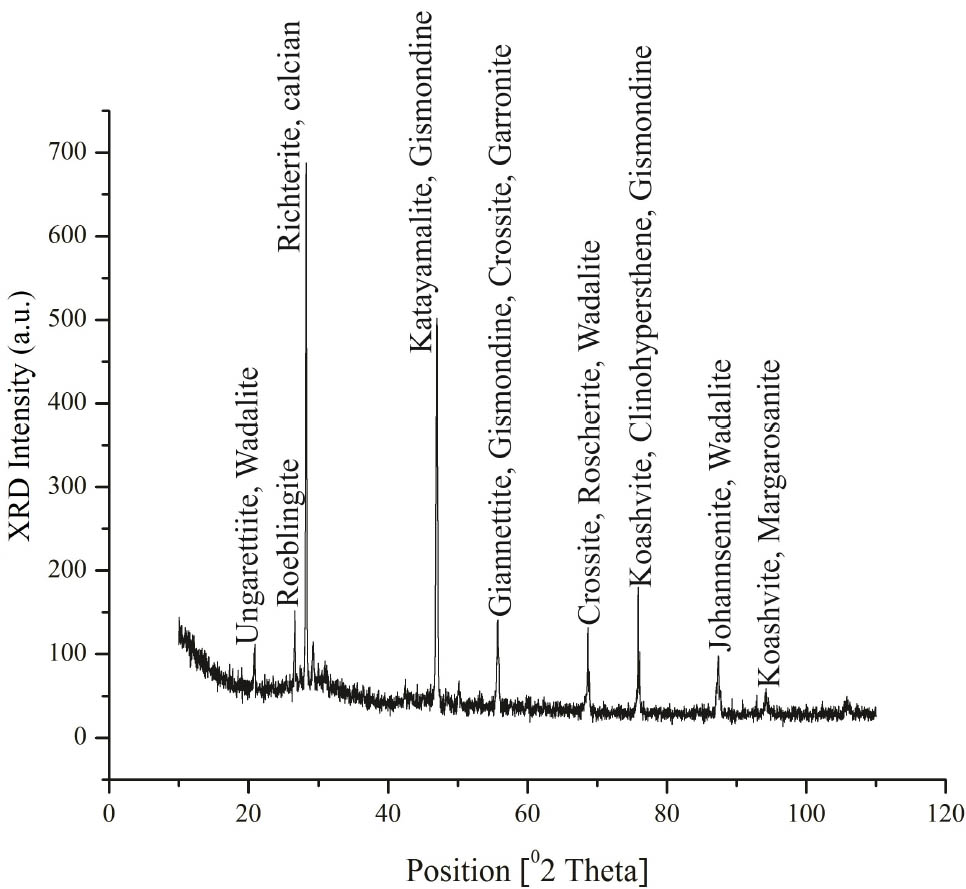
XRD analysis for slag sample 5
It has been observed from the mineral name and chemical names of the various phases formed that hydroxides (OxHy), silicates and oxides of most of the elements such as Si, Fe and Al are formed. Oxides have been formed due to oxidation of elements and hydroxides have been formed due to moisture pickup from atmosphere. Silicates are formed due to oxidation of different elements like Mn, Al, Mg in presence of Si. Sodium element is observed in about all of the phases which may be due to sodium silicate binder added during the agglomeration process in the formulation of fluxes. Fe is also observed in some phases which is indicated from the iron powder during mixing of flux mixtures.
6 Multi response optimalization of weld bead characteristics
After developing and analyzing the SQM, multi response optimization using Composite Desirability Approach suggested by Derringer and Suich [16] have been applied to optimize weld bead geometry [17, 18]. With an aim to maximize penetration area, maximize dilution and certain value of form factor (1.5) [6]; the flux mixtures have been optimized using multi response optimization technique. In this method, composite desirability, D is taken as the weighted geometric mean of individual desirability for the output responses. Weights are allocated to each and every output response according to the significance of that response in the process and then composite desirability is calculated as the following equation [19]:
Where n = number of output responses, di is desirability of individual response and wi = individual weight value 0 < wi < 1 and (w1 + w2 . . . . . . + wn) = 1
So according to the above constraints only one possible solution is provided; desirability as presented in Table 5.
Summary indicating effect of individual and binary mixtures on weld bead characteristics
| Type of effect | Mixture Type | Bead Width (W) | Bead Height (H) | Reinforcement Area (RA) | Penetration Area (PA) | Form Factor (FF) | Dilution |
|---|---|---|---|---|---|---|---|
| Individual Effect | Slag | Decrease | Decrease | Decrease | Decrease | Increase | Increase |
| Flux | Increase | Decrease | Increase | Increase | Increase | Increase | |
| Iron | Decrease | Decrease | Increase | Decrease | Increase | Decrease | |
| Binary Mixture Effect | Slag*Flux | Synergism | Synergism | Synergism | Synergism | Antagonism | Antagonism |
| Slag*Iron | Synergism | Synergism | Antagonism | Synergism | Antagonism | Synergism | |
| Flux*Iron | Synergism | Synergism | Synergism | Synergism | Antagonism | Synergism | |
Optimum composition of recycled slag-flux mixture for optimum bead characteristics
| Slag | Flux | Iron Powder | PA | FF | Dilution |
|---|---|---|---|---|---|
| 10 | 72.34 | 17.66 | 43.4485 | 2.043523 | 0.608029 |
7 Conclusions
Recycled slag-flux mixtures have been designed and formulated by mixing slag, fresh flux and ion powder using mixture design Scheffé's method.
Scheffe Quadratic Model (SQM) for weld bead characteristics have been developed in terms of weight percentage composition of slag, fresh flux and iron powder for submerged arc welding of stainless steel so that R-square values of the most of the models are more than 0.9.
Recycled slag tends to decrease all the bead characteristics; bead width; bead height; penetration area; reinforcement area but increases form factor and dilution which are further dependent on the former values.
Binary mixtures of slag with others components have mixed; synergic as well as antagonistic effect on different bead characteristics.
From the experimental work it is clear that weight composition of recycled slag up to 10% may be mixed with fresh flux to protect environment.
Funding information: The authors state no funding involved.
Author contributions: All authors have accepted responsibility for the entire content of this manuscript and approved its submission.
Conflict of interest: The authors state no conflict of interest.
References
[1] Annoni R, Souza PS, Petrániková M, Miskufova A, Havlík T, Mansur MB. Submerged-arc welding slags: characterization and leaching strategies for the removal of aluminum and titanium. J Hazard Mater. 2013 Jan;244–245:335–41.10.1016/j.jhazmat.2012.11.053Search in Google Scholar PubMed
[2] Datta S, Bandyopadhyay A, Pal PK. Slag recycling in submerged arc welding and its influence on weld quality leading to parametric optimization. Int J Adv Manuf Technol. 2008;39(3–4):229–38.10.1007/s00170-007-1224-4Search in Google Scholar
[3] Singh K, Pandey S. Recycling of slag to act as a flux in submerged arc welding. Resour Conserv Recycling. 2009;53(10):552–8.10.1016/j.resconrec.2009.04.006Search in Google Scholar
[4] Garg J, Singh K. Slag recycling in submerged arc welding and its effects on the quality of stainless steel claddings. Mater Des. 2016;108:689–98.10.1016/j.matdes.2016.07.028Search in Google Scholar
[5] Mastanaiah P, Sharma A, Reddy GM. Process parameters-weld bead geometry interactions and their influence on mechanical properties: A case of dissimilar aluminium alloy electron beam welds. Defence Technology. 2018;14(2):137–50.10.1016/j.dt.2018.01.003Search in Google Scholar
[6] Jindal S, Chhibber R, Mehta NP. Effect of welding parameters on bead profile, microhardness and H2 content in submerged arc welding of high-strength low-alloy steel. Proc Inst Mech Eng, B J Eng Manuf. 2014;228(1):82–94.10.1177/0954405413495846Search in Google Scholar
[7] Piepel GF, Szychowski JM, Loeppky JL. Augmenting Scheffé Linear Mixture Models with Squared and/or Cross product Terms. J Qual Technol. 2002;34(3):297–314.10.1080/00224065.2002.11980160Search in Google Scholar
[8] Cornell JA. Experiments with Mixtures: Designs, Models, and the Analysis of Mixture Data. 3rd ed. John Wiley & Sons; 2002. https://doi.org/10.1002/9781118204221.10.1002/9781118204221Search in Google Scholar
[9] Bailey N. Submerged arc welding ferritic steels with alloyed metal powder. Weld J. 1991;70(8):187–94.Search in Google Scholar
[10] O’Brien A, Guzman C. Welding Handbook: Welding processes, Part 2. Miami (FL): American Welding Society; 2004.Search in Google Scholar
[11] Anderson VL, McLean RA. Design of experiments: a realistic approach. New York: Marcell Dekker; 1974.Search in Google Scholar
[12] Hummel FA. Introduction to Phase Equilibria in Ceramics Systems. CRC Press Ltd; 1984.Search in Google Scholar
[13] Baune E, Bonnet C, Liu S, et al. Reconsidering the Basicity of a FCAW Consumable-Part 1: Solidified Slag Composition of a FCAW Consumable as a Basicity Indicator. Weld J. 2000;79(3):57s–65s.Search in Google Scholar
[14] Chang KL, Huang CT, Huang W, Liu YC, et al. Investigations of Microstructure and Phosphorus Distribution in BOF Slag. China Steel Technical Report. 2008;21:1–6.Search in Google Scholar
[15] Paniagua-Mercado AM, Lopez-Hirata VM. Chemical and physical properties of fluxes for SAW of low-carbon steels. Arc Weld. 2011;13:281–98.Search in Google Scholar
[16] Derringer G, Suich R. Simultaneous optimization of several response variables. J Qual Technol. 1980;12(4):214–9.10.1080/00224065.1980.11980968Search in Google Scholar
[17] Kumar A, Sharma R. Multi-response optimization of magnetic field assisted EDM through desirability function using response surface methodology. J Mech Behav Mater. 2020;29(1):19–35.10.1515/jmbm-2020-0003Search in Google Scholar
[18] Kumar P, Gupta M, Kumar V. Microstructural analysis and multi response optimization of WEDM of Inconel 825 using RSM based desirability approach. J Mech Behav Mater. 2019;28(1):39–61.10.1515/jmbm-2019-0006Search in Google Scholar
[19] Del Castillo E, Montgomery DC, McCarville DR. Modified desirability functions for multiple response optimization. J Qual Technol. 1996;28(3):337–45.10.1080/00224065.1996.11979684Search in Google Scholar
Appendix 1
Significance testing of SQM for weld geometry characteristics
| Predictor | Bead Width (W) | Bead Height (H) | Reinforcement Area (RA) | |||
|---|---|---|---|---|---|---|
| T0 | Whether significant or not* | T0 | Whether significant or not* | T0 | Whether significant or not* | |
| Slag | −3.61 | Significant | −2.92 | Significant | −3.15 | Significant |
| Flux | 11.89 | Significant | −0.70 | Not Significant | 0.92 | Not Significant |
| Iron | −4.40 | Significant | −5.85 | Significant | 0.79 | Not Significant |
| Slag*Flux | 5.76 | Significant | 3.25 | Significant | 6.52 | Significant |
| Slag*Iron | 7.78 | Significant | 6.07 | Significant | −2.44 | Significant |
| Flux*Iron | 4.46 | Significant | 6.88 | Significant | 2.64 | Significant |
| Predictor | Penetration Area (PA) | Form Factor (FF) | Dilution | |||
|---|---|---|---|---|---|---|
| T0 | Whether significant or not* | T0 | Whether significant or not* | T0 | Whether significant or not* | |
| Slag | −0.20 | Not Significant | 2.85 | Significant | 5.62 | Significant |
| Flux | 7.64 | Significant | 8.22 | Significant | 18.94 | Significant |
| Iron | −12.49 | Significant | 3.87 | Significant | −5.95 | Significant |
| Slag*Flux | 2.49 | Significant | −1.41 | Not Significant | −3.42 | Significant |
| Slag*Iron | 11.65 | Significant | −3.08 | Significant | 7.87 | Significant |
| Flux*Iron | 12.23 | Significant | −4.08 | Significant | 5.27 | Significant |
- *
Term is significant if |T0| > Tα, dof error (t0.05, 11 = 1.796)
ANOVA (F-test) of SQ Models
| Model | DOF | SS | MS | F value | P value | R-Square | |
|---|---|---|---|---|---|---|---|
| Bead width (W) | Model | 5 | 17.24 | 3.45 | 60.44 | 0.0001 | 0.96 |
| Linear Mixture | 2 | 10.96 | 5.48 | 96.11 | 0.0001 | ||
| Slag×Flux | 1 | 1.89 | 1.89 | 33.13 | 0.0001 | ||
| Slag×Iron | 1 | 3.45 | 3.45 | 60.55 | 0.0001 | ||
| Flux×Iron | 1 | 1.13 | 1.13 | 19.85 | 0.0010 | ||
| Error | 11 | 0.63 | 0.057 | ||||
| Total | 16 | 17.86 | |||||
| Bead height (H) | Model | 5 | 8.98 | 1.80 | 21.08 | 0.0001 | 0.91 |
| Linear Mixture | 2 | 2.69 | 1.34 | 15.76 | 0.0006 | ||
| Slag×Flux | 1 | 0.90 | 0.90 | 10.56 | 0.0077 | ||
| Slag×Iron | 1 | 3.14 | 3.14 | 36.85 | 0.0001 | ||
| Flux×Iron | 1 | 4.04 | 4.04 | 47.34 | 0.0001 | ||
| Error | 11 | 0.94 | 0.09 | ||||
| Total | 16 | 9.92 | |||||
| Reinforcement area (RA) | Model | 5 | 78.20 | 15.64 | 33.03 | 0.0001 | 0.94 |
| Linear Mixture | 2 | 41.95 | 20.97 | 44.30 | 0.0001 | ||
| Slag×Flux | 1 | 20.15 | 20.15 | 42.55 | 0.0001 | ||
| Slag×Iron | 1 | 2.82 | 2.82 | 5.95 | 0.0328 | ||
| Flux×Iron | 1 | 3.31 | 3.31 | 6.99 | 0.0229 | ||
| Error | 11 | 5.21 | 0.47 | ||||
| Total | 16 | 83.41 | |||||
| Penetration area (PA) | Model | 5 | 282.52 | 56.50 | 109.59 | 0.0001 | 0.98 |
| Linear Mixture | 2 | 176.26 | 88.13 | 170.94 | 0.0001 | ||
| Slag×Flux | 1 | 3.26 | 3.26 | 6.33 | 0.0287 | ||
| Slag×Iron | 1 | 71.51 | 71.51 | 138.69 | 0.0001 | ||
| Flux×Iron | 1 | 78.76 | 78.76 | 152.76 | 0.0001 | ||
| Error | 11 | 5.67 | 0.52 | ||||
| Total | 16 | 288.19 | |||||
| Form factor (FF) | Model | 5 | 1.37 | 0.27 | 52.00 | 0.0001 | 0.96 |
| Linear Mixture | 2 | 1.03 | 0.52 | 98.28 | 0.0001 | ||
| Slag×Flux | 1 | 0.03 | 0.03 | 5.84 | 0.0342 | ||
| Slag×Iron | 1 | 0.15 | 0.15 | 27.61 | 0.0003 | ||
| Flux×Iron | 1 | 0.25 | 0.25 | 48.46 | 0.0001 | ||
| Error | 11 | 0.06 | 0.01 | ||||
| Total | 16 | 1.42 | |||||
| Dilution | Model | 5 | 0.0236 | 0.0047 | 78.75 | 0.0001 | 0.97 |
| Linear Mixture | 2 | 0.0188 | 0.0094 | 156.58 | 0.0001 | ||
| Slag×Flux | 1 | 0.0008 | 0.0008 | 14.00 | 0.0033 | ||
| Slag×Iron | 1 | 0.0045 | 0.0045 | 74.29 | 0.0001 | ||
| Flux×Iron | 1 | 0.0020 | 0.0020 | 33.34 | 0.0001 | ||
| Error | 11 | 0.0007 | 0.0001 | ||||
| Total | 16 | 0.0243 | |||||
© 2021 Sandeep Jindal et al., published by De Gruyter
This work is licensed under the Creative Commons Attribution 4.0 International License.
Articles in the same Issue
- Research Articles
- The elastic-plastic properties of an anti-icing coating on an aluminum alloy: Experimental and numerical approach
- Optimization of recycled slag-fresh flux mixture based upon weld bead quality for submerged arc welding of stainless steel
- Design and optimization of differential capacitive micro accelerometer for vibration measurement
- Mechanical performance of abrasive sandpaper made with palm kernel shells and coconut shells
- Experimental investigation of WEDM process through integrated desirability and machine learning technique on implant material
- Mechanical properties and microstructural characteristics of rotating arc-gas metal arc welded carbon steel joints
- Assessment of cement replacement with fine recycled rubber particles in sustainable cementitious composites
- Structural response and sensitivity analysis of granular and asphaltic overlayment track considering linear viscoelastic behavior of asphalt
- Unmanned aerial vehicle evasion manoeuvres from enemy aircraft attack
- Effect of corrosion on surface degradation of galvanized steel in poultry dung, pig dung and urea solutions using rice straw as an inhibitor
- Mathematical modeling of AZ30 magnesium alloys at high temperature using the ring compression test and genetic algorithm method
- Study on hot deformation behavior and workability of stir-cast Al6063-6wt.% steelp based composites
- The effects of processing parameters on the formation of oxide layers in aluminium alloys using plasma electrolytic oxidation technique
- Behavior of green reactive powder mortar reinforced with steel fibers
- On the hygrothermal properties of sandcrete blocks produced with sawdust as partial replacement of sand
- Mechanical behavior of thin-walled steel under hard contact with rigid seabed rock: Theoretical contact approach and nonlinear FE calculation
- Mechanical properties and microstructural characteristics of rotary friction welded dissimilar joints of rolled homogeneous armor steel and medium carbon steel
- Studies of carboxylated nitrile butadiene rubber/butyl reclaimed rubber (XNBR/BRR) blends for shoe soles application
- Mechanical properties of wire arc additive manufactured carbon steel cylindrical component made by gas metal arc welding process
- Synthesis and mechanical characterization of Si3N4 reinforced copper-tin matrix composites
- Analysis of plated-hull structure strength against hydrostatic and hydrodynamic loads: A case study of 600 TEU container ships
- Mechanical performance investigation of lignocellulosic coconut and pomegranate / LDPE biocomposite green materials
- Special Issue MICAP-2021
- Double hydrothermal synthesis of iron oxide/silver oxide nanocomposites with antibacterial activity**
- Enhanced photocatalytic activity of TiO2-CdS composite nanofibers under sunlight irradiation**
- Structural properties of CoxCu1−xFe2O4 solid solution**
- Green-synthesis of Ag2O nanoparticles for antimicrobial assays**
- Effect of current density on the porous silicon preparation as gas sensors**
- A mechanochemical preparation, properties and kinetic study of kaolin–N, P fertilizers for agricultural applications**
- Impact strength of surface treated SS316L wires reinforced PMMA**
- Computational studies on electronic and optical properties of dopamine derivatives structure: A DFT study**
- Multilayer coating effects on the thermal conductivity of tools using an electric furnace technique**
- The positron and mechanical parameters of a cold-worked aluminum alloy (3004) Using PALT, PADBT and HV**
- Effect of thermal annealing on the structural and optical properties of TiO2 nanostructures**
- Improvement of forging die life by failure mechanism analysis**