Mechanical properties and microstructural characteristics of rotating arc-gas metal arc welded carbon steel joints
-
Nallasamy Sankar
 ,
Sudersanan Malarvizhi
,
Sudersanan Malarvizhi

Abstract
The main problem associated with high thickness carbon steel plate's narrow range or “V” groove welding in conventional welding processes is the sagging of the molten pool due to gravity, which in turn leads to defects formation and deteriorates mechanical properties. This problem could be overcome by the rotating arc gas metal arc welding (RA-GMAW) technique. This investigation aims to evaluate mechanical properties and metallurgical characteristics of high thickness IS2062 Gr-B carbon steel joints welded by RA-GMAW technique. The experimental results show that RA-GMAW joint exhibited higher (598 MPa) tensile strength, higher hardness (220 HV) at weld metal region, and lower impact toughness (137 J) than the unwelded base metal. This is due to the presence of fine acicular ferrite and widmanstatten ferrite matrix mixed with fine lamellar pearlite microstructure in the weld metal region.
1 Introduction
High thickness carbon steels (C-Mn) are widely used in structural fabrication work. These steels are traditionally welded by shielded metal arc welding (SMAW), gas metal arc welding (GMAW), flux core arc welding (FCAW) and submerged arc welding (SAW) processes. Generally, single “V” butt joint configuration is used to weld the plates having thickness of below 10 mm and double “V” butt joint configuration is used to weld higher thickness plates (above 12 mm thickness). While preparation of the joint configuration, lot of base materials is removed by machining processes. While fabricating the joints, large volume of filler metal is added by welding processes. Generally, multi pass welding techniques using stationary arc are used to fabricate high thickness plates which reduces the productivity and also deteriorates the joint performance and mechanical properties due to higher heat input supplied. To overcome, this problem recently, a new “rotating arc” technique was developed and patented by “Weld Revolution, USA”. This technique is popularly known as “SPIN ARC” welding technique and it is a variant of gas metal arc welding (GMAW) process [1, 2, 3]. The rotating arc welding set up is displayed in Figure 1. In this technique the welding arc can be rotated at higher speed both clockwise and counterclockwise direction. The rotation of arc results in improved sidewall fusion, reduced number of passes and refined microstructure in the weld metal region. This technique is currently utilized for welding of high thickness steel plates.

Rotational arc welding machine set up.
Rao et al. [4] studied the rotation arc mechanism to prevent undesirable convex type penetration. The author observed that the depth of penetration decreases with an increase in arc speed. Ning et al. [5] experimented rotary arc horizontal narrow gap welding of quenched and tempered steel. They found that the slag inclusion was formed at the interlayer of the lower sidewall. Kumar et al. [6] investigated the effect of rotary arc welding process parameters such as arc rotating speed, the ratio of wire feed rate to travel speed, wire feed rate, and eccentricity on weld bead geometry. It was observed that eccentricity has maximum effect on convexity followed by arc rotational speed, the ratio of wire feed rate to travel speed, and wire feed rate. Zhang et al. [7] investigated the effect of rotary wire motion on fusion zone shape and microstructure. They found that the raise in wire rotational speed decreased the depth of penetration because the rotational flow of the weld pool liquid metal reduced the flow in the vertical direction. Parthiban et al. [8] experimented on the rotating arc welding of 10 mm thick C1018 low carbon steel plates. They have reported that full penetration joint was achieved with a welding current of 300 Amps, Voltage of 35 V, rotating diameter of 3 mm, and rotating speed of 3000 rpm without any defects in three passes. Recently, Vemu et al. [9] studied the effect of arc rotational speed on mild steel plates of 6 mm thick and they inferred that increasing the rotational speed improves the mechanical properties of weld joint. However, published information on rotating arc gas metal arc welding (RA-GMAW) of thick plates is very scant. Systematic studies have not been reported yet to correlate the mechanical properties and microstructural characteristics of RA-GMAW joints. Hence, in this investigation, an attempt has been made to join 12 mm thick carbon steel plates by the RAGMAW technique and to evaluate mechanical properties and microstructural characteristics of welded joints.
2 Experimental work
The base metal (BM) used in this investigation was IS2062 Gr-B steel. The optical microstructure of BM exhibits a pearlite structure in an elongated polygonal ferrite matrix (Figure 2). Rolled plates of 12 mm thick was cut to the required dimensions (300×150×12 mm) by an abrasive cutting machine. The square butt joint configuration was prepared for rotating arc welding process, as shown in Figure 3. Figures 3a) and 3b) show the top view and front view of the weld joint configuration. The initial joint configuration was obtained by fastening the plates in position using tack welding. The direction of welding was carried normal to the rolling direction. All essential care was taken to avoid joint distortion and the joints were made after holding the plates in a welding fixture. The ER70S6 (1.2 mm) filler wire was used to fabricate the joint. Vacuum spectrometer was used to analyse the chemistry of the filler wire and BM. Sparks were ignited at various locations of the BM and their spectrum was analyzed for the estimation of respective alloying elements. The chemical composition of the BM and filler metal (FM) are presented in Table 1. The mechanical properties of BM and filler metal are presented in Table 2. The optimized process parameters used to fabricate the joints are given in Table 3.

Optical microstructure of base metal.

Configuration of weld joint: a) top view, b) side view.
Chemical composition of base metal (BM) and filler metal (FM).
| Material | Specification | C | Si | Mn | P | S | Cr | Mo | Ni | Fe |
|---|---|---|---|---|---|---|---|---|---|---|
| BM | IS2062 | 0.25 | 0.07 | 0.65 | 0.028 | 0.038 | 0.08 | 0.005 | 0.013 | Bal |
| FM | ER70S6 | 0.07 | 0.86 | 1.44 | 0.014 | 0.008 | 0.025 | 0.002 | 0.014 | Bal |
Mechanical properties of base metal (BM) and filler metal (FM).
| Material | Yield Tensile strength (MPa) at 0.2% strain | Ultimate tensile strength (MPa) | Elongation (%) at 50 mm gauge length | Charpy impact toughness @ RT (J) |
|---|---|---|---|---|
| BM | 437±5 | 547±7 | 28±3 | 170±6 |
| FM | 424±6 | 518±4 | 28±2 | 163±3 |
Optimized welding parameters used to fabricate the joint.
| Parameters | Unit | Value |
|---|---|---|
| Filler wire diameter | mm | 1.2 |
| Arc Rotational Speed | rpm | 1500 |
| Arc Rotating Diameter | mm | 3 |
| Root gap | mm | 8 |
| Contact Tip to work Distance | mm | 20 |
| Gas Flow Rate | lit/min | 15 |
| Welding current | A | 130 |
| Arc voltage | V | 25 |
| Welding Speed | mm/min | 250 |
| Wire feed rate | mm/min | 165 |
| Heat input | kJ/mm | 0.78 |
The photograph of welded joint, scheme of extraction of tensile and impact specimens from the joint is show in Figure 4. The welded joints were cut and machined to the required dimensions (as shown in Figure 5) for preparing tensile and impact toughness specimens corresponding to American Society for Testing of Materials (ASTM) guidelines. Two different tensile samples were prepared to assess the transversal tensile properties. The smooth (unnotched) tensile specimens were prepared to evaluate the yield strength, tensile strength and elongation. Notched specimens were prepared to evaluate the notch tensile strength and notch strength ratio (NSR) of the weld joints. The notch sensitivity or notch brittleness is determined by the notch strength ratio (NSR).

Welded joint photograph and scheme of extraction from the weld joint.
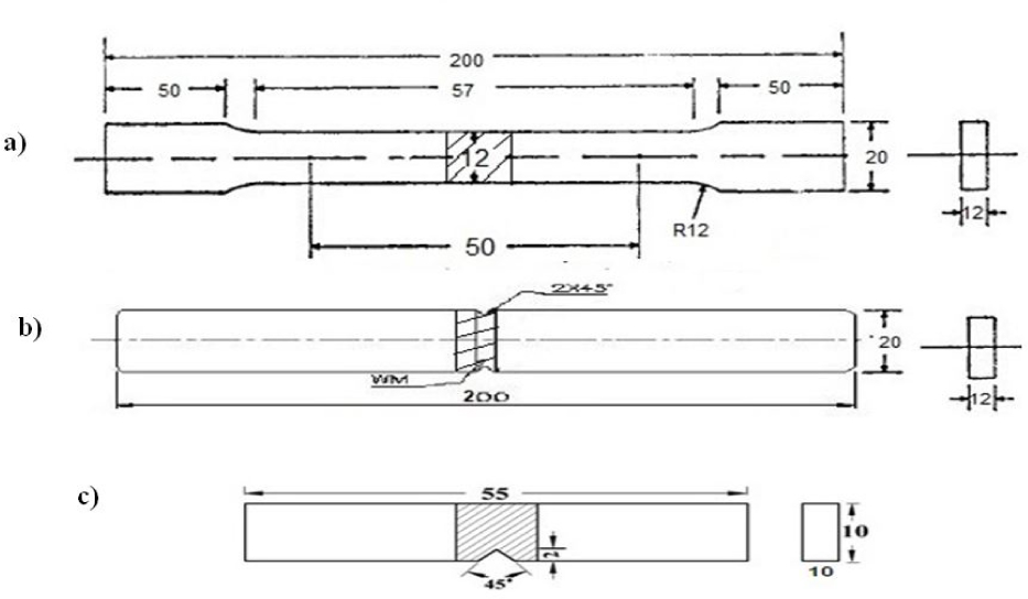
Dimensions of the specimens: a) smooth tensile specimen, b) notch tensile specimen, c) impact toughness specimen.
If the NSR is less than one (<1) than, the material is notch brittle [10]. The tensile test was carried out in a 100 kN, electro-mechanical controlled universal testing machine. The specimen was loaded at the rate of 1.5 kN min−1 as per ASTM E8M-04specification [11], so that the tensile specimen undergoes uniform deformation. The specimen finally fails after necking and the load versus displacement was recorded. The 0.2% offset yield strength was derived from the diagram. The percentage of elongation and reduction in cross-sectional area were also evaluated. The efficiency of the weld joint was also calculated using following equations [12, 13].
The Charpy impact test was carried out at ambient temperature by means of a pendulum-type impact testing machine. A Vickers microhardness testing machine was employed for measuring the hardness across the weld center, middle and top. Microstructure examination of welds was performed using a light optical microscope. The specimen was etched with 2% nital reagent to reveal the microstructure of the weld region and HAZ regions. The fractured surface of the tensile and impact specimen was analyzed using a scanning electron microscope (SEM) at higher magnification to study the nature of fracture.
3 Results
3.1 Macrostructure and microstructure
The macrostructures of rotating arc weld joint depicts in Figure 6. From this macrograph the weld zone exhibited a very good sidewall fusion without any internal defects. Figure 6) shows the square butt joint without edge preparation. The interface of weld and BM was very narrow and width of HAZ also reduced, due to low heat input. This type of good bead profile and side wall fusion is difficult to attain in conventional welding process. The base metal contains primary structure is separated by dark pearlite strips mixed with white ferrite matrix (Figure 2). The ferrite grains appear slightly elongated in BM.

Macrostructure of weld joint.
Figure 7 Shows the different region optical microstructure (OM) of top, middle and bottom pass of the weld metal (WM), coarse grain heat affected zone (CGHAZ), fine grain heat affected zone (FGHAZ) and interface (IF) of rotating arc weld joint. The WM region of top pass (Figure 7(a)) exhibits the high volume fraction of acicular ferrite(AF) matrix mixed with fine lamellar pearlite (FLP)microstructure. Due the higher volume percentage of AF exhibits higher hardness and higher strength of weld zone. Figure 7(b) shows presence of polygonal ferrite (PF) matrix mixed with fine lamellar pearlite (FLP) microstructure. The WM region of bottom pass (Figure 7(c)) exhibits PF matrix mixed with FLP microstructure but PF phase is slightly higher compared to middle and top passes. This is due to the heat accumulation in the bottom pass due to middle and top passes. This leads to formation of PF structure in this region. And hence the hardness various appreciably in bottom pass.
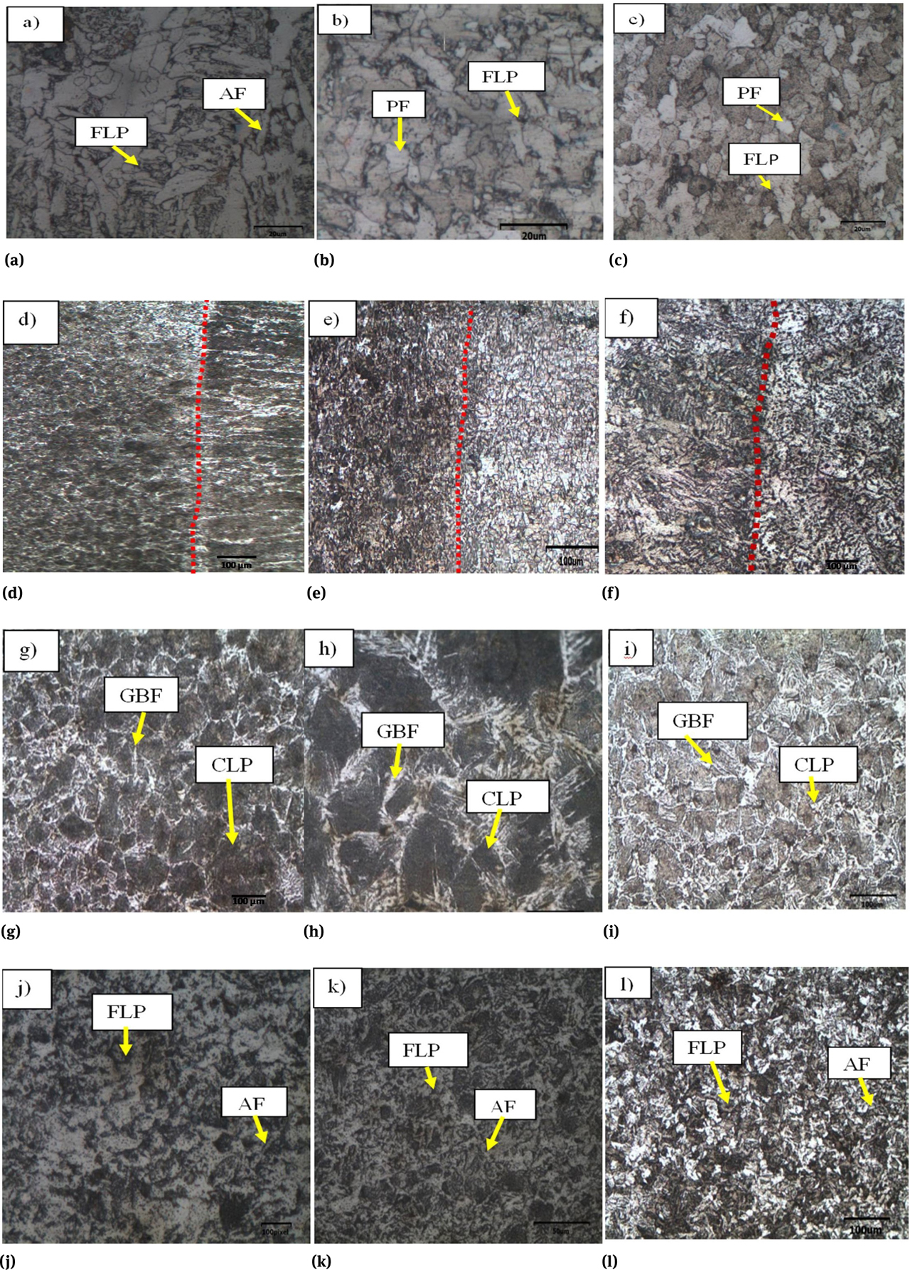
Different region optical micrographs of top, bottom and middle pass of the weld joint.
Figure 7(d–f) shows IF region of weld joint. It clearly shows the IF region is fully mixed with base metal and also no sagging defects found at both sides, because of complete fusion onto the side walls due to the arc rotation mechanism. Figure 7(g–i) shows grain boundary ferrite matrix (GBF) and a relatively reduced amount of a coarse lamellar pearlite (CLP) structure of CGHAZ region. Due this GBF structure the hardness was reduced in CGHAZ region Figure 7(j–l) shows the very fine lamellar pearlite (FLP) phase mixed with fine AF microstructure. So the FGHAZ region showed higher hardness compared then CGHAZ region.
3.2 Transverse tensile properties and impact toughness
The transverse tensile test results of BM and WM presented in Table 4 are the average of three tensile test specimens. All the welded joints are failed in BM region only. The tensile and notch tensile specimens (after the test) are shown in the Figure 8. The stress vs. Strain curves recorded during tensile test are shown in Figure 9. The welded joint showed 10% higher ultimate tensile strength and yield strength compared to BM. The BM and welded joint elongation were 26% and 23%, respectively. It indicates that there is a 12% reduction in ductility of the welded joint compared to BM. The notch tensile strength of the BM is 670 MPa; however the notch tensile strength of welded joint is 727 MPa. Thus, there is a 10 %increase in the notch tensile strength of welded joints. Another notch tensile parameter NSR was found to be greater than one (>1). The NSR is 1.22 for the BM, 1.15 for the welded joint respectively. This indicates that BM and weld metal are insensitive to notches and fall within the category of ductile materials. The Charpy impact toughness values of welded joint are shown in Table 4. Photographs of impact test specimens before and after testing is displayed in Figure 10. The impact toughness of BM and welded joint are found to be 170 J and 137 J respectively. From the results, it is understood that impact toughness of weld joint is 20% lower than base material.
Transverse tensile properties and impact toughness of welded joint.
| 0.2% Yield strength (MPa) | Ultimate tensile strength (MPa) | Elongation in 50 mm gauge length (%) | Notch tensile strength (MPa) | Notch strength ratio (NSR) | Joint efficiency (%) | Location of failure | Charpy impact toughness (J) @ RT |
|---|---|---|---|---|---|---|---|
| 467±11 | 598±4 | 23±3 | 727±8 | 1.15 | 110 | BM | 137±5 |

Photographs of Tensile Test Specimen (after testing): a) Unnotched Tensile Specimen, b) Notched Tensile Specimen.

Stress – Strain curves for the base metal and welded joint

Photographs of Impact Test Specimen: a) Impact toughness specimen (before Testing), b) Impact toughness specimen (After Testing).
3.3 Fracture surface analysis
The fractured surfaces of the tensile and impact toughness tested specimen analyzed by SEM. The photograph of close-up view of failed location, low magnification (200x) SEM images and high magnification (1000x) SEM images of smooth tensile, and impact toughness tested BM and welded specimen are displayed in Figures 11–12. Figure 11a shows the close-up view of failed location of smooth tensile specimen of BM. The thickness and width of the specimens are extensively reduced to 3.5 mm and 2.5 mm respectively. This shows that prior to failure, the specimen is subjected to higher load. Lower and higher magnifications of SEM images of BM smooth tensile specimen are shown in Figures 11b,c. Both the images consist of fine equiaxed dimples, which indicates ductile mode of failure [14]. Figure 11d showed the close-up view of failed location weld joint (smooth tensile specimen). The thickness and width of the specimens are reduced to 4 mm and 2.5 mm respectively. This shows that prior to failure, the specimen has absorbed high energy. Lower and higher magnification images of fracture surface of weld joint (smooth tensile specimen) are shown in Figure 11e, f. Fracture surface consists of smoother and more number of tiny dimples [15] and, hence it is recorded higher tensile strength compared to BM.

Fracture surfaces of BM and WM tensile specimens.

Fracture surfaces of BM and WM impact specimens.
The photograph of failed impact toughness specimen of the BM is shown in Figure 12a. Lower and higher magnification of fracture surface of impact toughness specimen of BM are shown in Figure 12b,c. The fracture surface shows quasi-cleavage fracture and also many dimples found in the fracture surface [16]. The photograph of failed impact toughness specimen of the weld joint is shown in Figure 12d. Lower and higher magnification of fracture surface of weld joint (impact specimen) are shown in Figures 12e, f. The fracture surface consists of shallow dimples and some flat facets [17] and this is in correlation with low impact toughness exhibited by BM.
3.4 Microhardness
The hardness variation across the weld joint was measured using microhardness testing machine. Figure 13 illustrates the microhardness distribution profile of the welded joint. It can be noted that the lower hardness was recorded in the BM and the higher hardness was recorded at bottom of FGHAZ region of the welded joints. The average hardness of unwelded BM was 185 HV and the welded joint exhibits an average hardness of a 220 HV. The transverse tensile specimens failed at BM region due to the lower hardness of the BM compared to WM hardness. The FGHAZ region recorded higher hardness (226 HV) than BM hardness (185 HV). This is due to presence of very FLP phase mixed with fine AF microstructure. The WM region shows 18 % higher hardness compared to the base metal. From the hardness survey results, it is clear that the top region weld metal showed higher hardness compared to middle and bottom of the weld region.

Microhardness for weld joint.
4 Discussion
In general rotating arc welding process was developed to reduce the heat input, improved sidewall fusion, increase productivity by eliminating the edge preparation and reducing the number of passes without compromising the strength of high thickness weld joint. In this process the filler wire is rotated by special type of rotating motor inside the arc torch itself. The rotation of the wire will rotate the arc between the plates. During wire rotation arc, the arc is rotated in a circular motion to create a centrifugal force for the arc to deposit the metal providing good side wall fusion and subsequent grain refinement after the deposition. The centrifugal force created on the droplet during transfer of molten metal to the weld pool creates good flow ability of the molten metal increasing the cooling rate with reduced heat input along the weld centers. This above overall phenomenon creates a huge impact on molten pool solidification. Figure 14 shows the arc rotation during welding.

Rotating Arc technology; operation at rotating arc welding high speed video frame.
In rotating arc welding process rotational diameter and rotational speed (frequency) are the very essential parameters. When the rotating diameter increased, the arc centre deviated from centre of the weld. So the arc force in the center of the weld decreases. These results in arc force higher the both sidewalls. Rotating arc creates better sidewall fusion compared to the other welding processes and also the liquid metal in the molten pool was flown from the two ends to the centre of the weld (as shown in Figure 14). Hence very good weld surface was obtained [18]. When increasing rotation speed (frequency), the melting rate of the welding wire increased and penetration also increased [19].
The presence of FLP microstructure mixed with the AF and WF matrix (Figure 12. e, f, g) in the weld joint region. AF dominated microstructure is attractive microstructures for higher tensile strength and hardness, than PF, GP, etc. [20]. This is mainly due to the welded joint showed higher tensile strength (598 MPa) than BM and this is also attributed to the higher hardness of weld metal region. The rotating arc welding process provides very low heat input (0.78 kJ/mm). The higher heat input leads to grain growth in the weld pool, while the low heat input provides no time for grain growth, as it solidifies faster [21]. The formation of different types of ferrite microstructures is mainly because of the different cooling rate experienced by the weld metal. The hardness of the top pass of the weld metal region is 223 HV.
In the weld metal zone, grain size refinement takes place due to the arc rotation and stirring action of the rotary arc process. It also increases the hardness of the weld metal region through grain refinement. These reasons attribute for the high tensile strength and hardness of the weld metal region. The impact toughness of BM was higher (170 J) than weld (137 J) joint, due to low heat input and fine grain AF phase formed in the WM. The rotation of the arc of the process had an important effect on the impact resistance of the WM. When the heat input was low, the formation of FLP and AF microstructure in WM leads to high hardness and low impact toughness of the welded joint. It is easy for the propagation of micro cracks along the fine pearlite grain boundaries. Smaller grain size will hinder the dislocations more than the large grain size, due to a large number of grain boundaries per unit area [22, 23]. Consequently, the dislocations pile up at the grain boundaries and generate internal stresses to overcome dislocation pile up stress [24]. Hence BM has higher impact toughness compared to the welded joint.
5 Conclusions
The following important conclusions relating to the mechanical properties and microstructural features are derived from this investigation.
From macrostructural analysis it is confirmed that, 12 mm thick IS2062 Gr-B carbon steel plates can be successfully welded by RA-GMAW technique without formation of any kind of internal and external defects with full depth of penetration.
Strength properties (yield strength, tensile strength, and notch tensile strength) of RA-GMAW joints are higher compared to unwelded base metal and undiluted filler metal.
Impact toughness of the RA-GMAW joint is lower than the unwelded base metal and undiluted parent metal at room temperature. This is due to lower ductility (elongation) and higher hardness of weld metal than base metal.
The RA-GMAW joint exhibited 10% higher strength properties, 20% higher hardness of weld metal, 10% lower ductility and 20% lower impact toughness than the unwelded base metal. This is due to the presence of fine lamellar pearlite mixed with acicular ferrite and widmanstatten ferrite matrix microstructure in the weld metal region.
Funding information:
The authors express gratitude to the Director, Combat Vehicles Research Development Establishment (CVRDE), Defence Research & Development Organization (DRDO), Avadi, and Chennai for the financial support through rendered through CARS project (Project No. CVRDE/18CR0004/MBT/17-18/LP).
Author contributions:
All authors have accepted responsibility for the entire content of this manuscript and approved its submission.
Conflict of interest:
The authors state no conflict of interest.
References
[1] Bijaya KK, Soumya SD, Swapan KK, Bibhuti BB, et.al. Effect of welding parameters on mechanical and microstructural properties of GMAW and SMAW mild steel joints. Iro mak & Steel. 2020; 47(8):844–851.10.1080/03019233.2019.1623592Search in Google Scholar
[2] Dongki C, Hun L, Sung K, Hyoung CK, Soong KH, Sang YS, et.al. Microstructure and charpy impact properties of FCAW and SAW heat affected zones of 100 mm thick steel plate for offshore platforms. Met Mate Int. 2020; 26:867–881.10.1007/s12540-020-00626-8Search in Google Scholar
[3] Harsh S, Balram R, Rudra PS, et.al. A review paper on effect of input welding process parameters on structure and properties of weld in submerged arc welding process. Mat T Pro. Elsevier publications, 2020; 26.10.1016/j.matpr.2020.02.422Search in Google Scholar
[4] Srinivasa RP, Gupta OP, Murthy N. et al. A study on the weld bead characteristics in pulsed gas metal arc welding with rotating arc. Proceedings of OMAE04 23rd. International Conference on Offshore Mechanics and Arctic Engineering. 2004; 20–25.Search in Google Scholar
[5] Guo N, Yang C, Du Y, Zhang L. et al. Rotating arc horizontal narrow gap welding of high strength quenched and tempered steel. Article in china welding. 2010; 19(4):31–35.Search in Google Scholar
[6] Sanjay KP, Srinivasa R, Ramakrishna A. et al. Effects of eccentricity and arc rotational speed on weld bead geometry in pulsed GMA welding of 5083 aluminum alloy. J Mech Eng Res. 2011; 3(6):186–196.Search in Google Scholar
[7] Hongtao Z, Qing C, Jihou L, Haolu H, and Jicai F, et al. A novel rotating wire GMAW process to change fusion zone shape and microstructure of mild steel, . 2014;(15) 01–103.Search in Google Scholar
[8] Parthiban K, Siva SN, Sankaranarayanasamy K, Arungalai VS, et al. Studies on spin arc welding process on the behavior of C1018 plates-an insight into mechanical and metallurgical transformation. Mat Res Exp, IOP Publishing Ltd, 2019;6(10).10.1088/2053-1591/ab135dSearch in Google Scholar
[9] Vara PV, Pramila DM, et al. Experimental study of mild steel weld bead mechanical properties in rotational arc welding process. 2019; 2214–7853.Search in Google Scholar
[10] Parmar R.S, Welding Engineering and Technology. 2016; ISBN No: 81-7409-028-2.Search in Google Scholar
[11] Designation ASTM. Standard test methods for notched bar impact testing of metallic materials. 2016;Search in Google Scholar
[12] Chandan P, Manas MM, Padeep K, F. Daniel, B. Adhithan et.al. Softening mechanism of P91 steel weldments using heat treatments. Archives of civilian mechanical engineering. 2019;19:297–310.10.1016/j.acme.2018.10.005Search in Google Scholar
[13] Pandey. C, Mahapatra.M.M, Kumar.P, Saini.N, et al. Effect of strain rate and notch geometry on tensile properties and fracture mechanism of creep strength enhanced ferritic P91 steel. J Nuc Mat. 2017; 498.10.1016/j.jnucmat.2017.10.037Search in Google Scholar
[14] Karthick. K, Malarvizhi. S, Balasubramanian. V, Krishnan S.A, Sasikala. G and Shaju K. Albert et al. Tensile properties of shielded metal arc welded dissimilar joints of nuclear grade ferritic steel and austenitic stainless steel. Journal of the mechanical behavior of materials. 2016; 25(5–6):171–178.10.1515/jmbm-2017-0005Search in Google Scholar
[15] Balaguru V, Balasubramanian V, Sivakumar P et.al. Effect of weld metal composition on impact toughness properties of shielded metal arc welded ultra-high hard armor steel joints. J Mech Beh Mat. 2020; 29:186–194.10.1515/jmbm-2020-0019Search in Google Scholar
[16] Ramaswamy A, Malarvizhi S, Balasubramanian V, et al. Influence of post weld heat treatment on tensile properties of cold metal transfer (CMT) arc welded AA6061-T6 aluminum alloy joints. J Mech Beh Mat. 2019; 28:135–145.10.1515/jmbm-2019-0015Search in Google Scholar
[17] Tushar S, Balasubramanian V, Malarvizhi S, Venkateswaran T, Sivakumar D, Effect of delta current and delta current frequency on tensile properties and microstructure of gas tungsten constricted arc (GTCA) welded Inconel 718 sheets. J Mech Beh Mat. 2019; 28:186–200.10.1515/jmbm-2019-0020Search in Google Scholar
[18] Hu L, Hua JZ, Deg Z, Jing C, Shang YL, et al. Effects of arc-sidewall distance on arc appearance in narrow gap MAG welding. Spr Int Pub Swd. Rob Wel, Ine Auto. 2015;Search in Google Scholar
[19] Ning G, Yanfei H, Chuanbao J, Yongpeng D, et.al. Effects of wire rotating frequency on metal transfer process in rotating arc narrow gap horizontal GMAW. Adv Mat Res. 2011; 189–193:3395–3399.10.4028/www.scientific.net/AMR.189-193.3395Search in Google Scholar
[20] Seyed M, Kazem H, Abbass ZH, et al. Effects of ferrite phase characteristics on microstructure and mechanical properties of thermo mechanically-processed low-silicon content TRIP-assisted steels, . :229–236.Search in Google Scholar
[21] Li CL, Yong Q, et al. Effect of welding heat input on grain size and microstructure of 316l stainless steel welded joint. 2013;331:578–582.10.4028/www.scientific.net/AMM.331.578Search in Google Scholar
[22] Elwazri AM, Wanjara P, et al. The effect of microstructural characteristics of pearlite on the mechanical properties of hypereutectoid steels. A.2002; 404:1–2.10.1016/j.msea.2005.05.051Search in Google Scholar
[23] Morris J. The Influence of Grain Size on the Mechanical Properties of Steel. US. 2017;Search in Google Scholar
[24] Armstrong R.W, Dislocation Pile-Ups, Strength Properties and Fracturing. Adv Mat Sci. 2004; 48:1–12.Search in Google Scholar
© 2021 Nallasamy Sankar et al., published by De Gruyter
This work is licensed under the Creative Commons Attribution 4.0 International License.
Articles in the same Issue
- Research Articles
- The elastic-plastic properties of an anti-icing coating on an aluminum alloy: Experimental and numerical approach
- Optimization of recycled slag-fresh flux mixture based upon weld bead quality for submerged arc welding of stainless steel
- Design and optimization of differential capacitive micro accelerometer for vibration measurement
- Mechanical performance of abrasive sandpaper made with palm kernel shells and coconut shells
- Experimental investigation of WEDM process through integrated desirability and machine learning technique on implant material
- Mechanical properties and microstructural characteristics of rotating arc-gas metal arc welded carbon steel joints
- Assessment of cement replacement with fine recycled rubber particles in sustainable cementitious composites
- Structural response and sensitivity analysis of granular and asphaltic overlayment track considering linear viscoelastic behavior of asphalt
- Unmanned aerial vehicle evasion manoeuvres from enemy aircraft attack
- Effect of corrosion on surface degradation of galvanized steel in poultry dung, pig dung and urea solutions using rice straw as an inhibitor
- Mathematical modeling of AZ30 magnesium alloys at high temperature using the ring compression test and genetic algorithm method
- Study on hot deformation behavior and workability of stir-cast Al6063-6wt.% steelp based composites
- The effects of processing parameters on the formation of oxide layers in aluminium alloys using plasma electrolytic oxidation technique
- Behavior of green reactive powder mortar reinforced with steel fibers
- On the hygrothermal properties of sandcrete blocks produced with sawdust as partial replacement of sand
- Mechanical behavior of thin-walled steel under hard contact with rigid seabed rock: Theoretical contact approach and nonlinear FE calculation
- Mechanical properties and microstructural characteristics of rotary friction welded dissimilar joints of rolled homogeneous armor steel and medium carbon steel
- Studies of carboxylated nitrile butadiene rubber/butyl reclaimed rubber (XNBR/BRR) blends for shoe soles application
- Mechanical properties of wire arc additive manufactured carbon steel cylindrical component made by gas metal arc welding process
- Synthesis and mechanical characterization of Si3N4 reinforced copper-tin matrix composites
- Analysis of plated-hull structure strength against hydrostatic and hydrodynamic loads: A case study of 600 TEU container ships
- Mechanical performance investigation of lignocellulosic coconut and pomegranate / LDPE biocomposite green materials
- Special Issue MICAP-2021
- Double hydrothermal synthesis of iron oxide/silver oxide nanocomposites with antibacterial activity**
- Enhanced photocatalytic activity of TiO2-CdS composite nanofibers under sunlight irradiation**
- Structural properties of CoxCu1−xFe2O4 solid solution**
- Green-synthesis of Ag2O nanoparticles for antimicrobial assays**
- Effect of current density on the porous silicon preparation as gas sensors**
- A mechanochemical preparation, properties and kinetic study of kaolin–N, P fertilizers for agricultural applications**
- Impact strength of surface treated SS316L wires reinforced PMMA**
- Computational studies on electronic and optical properties of dopamine derivatives structure: A DFT study**
- Multilayer coating effects on the thermal conductivity of tools using an electric furnace technique**
- The positron and mechanical parameters of a cold-worked aluminum alloy (3004) Using PALT, PADBT and HV**
- Effect of thermal annealing on the structural and optical properties of TiO2 nanostructures**
- Improvement of forging die life by failure mechanism analysis**