Mechanical properties of wire arc additive manufactured carbon steel cylindrical component made by gas metal arc welding process
-
Bellamkonda Prasanna Nagasai
 ,
Sudersanan Malarvizhi
,
Sudersanan Malarvizhi

Abstract
Wire arc additive manufacturing (WAAM), a welding-based additive manufacturing (AM) method, is a hot topic of research since it allows for the cost-effective fabrication of large-scale metal components at relatively high deposition rates. In the present study, the cylindrical component of low carbon steel (ER70S-6) was built by WAAM technique, using a GMAW torch that was translated by an automated three-axis motion system using a rotation table. The mechanical properties of the component were evaluated by extracting tensile, impact toughness and hardness specimens from the two regions of the building up (vertical) direction. It is found that the tensile properties of the built material exhibited anisotropic characteristics. The yield strength and ultimate tensile strength varied from 333 to 350 MPa and from 429 to 446 MPa, respectively, (less than 5 % variation).
1 Introduction
Additive manufacturing (AM) has been developed in recent decades as a new technology for manufacturing parts, particularly interior structures, which have very complicated geometry. The AM technology enables a physical object to be produced directly from its CAD model with no additional resources, such as cutting tools, jigs and cooling fluids [1]. AM utilizes only the amount of materials required to manufacture parts and support structures if necessary. As a result, material waste and environmental effects might be minimised. [2, 3]. Topological optimization for raw material savings is also possible with AM [4]. AM technologies, particularly metallic AM technologies, are now widely employed in the fields of aeronautics, automobiles, and biomedical engineering.
WAAM is considered to be the most advantageous metallic AM technology for producing large-scale components. A welding source is used in WAAM systems to produce an arc between the electrode and the workpiece, which melts the metallic wire. Gas Metal Arc Welding (GMAW), Plasma Arc Welding (PAW) and Gas Tungsten Arc Welding (GTAW) are examples of welding sources [5, 6]. The advantage of WAAM is its high deposition rate, low cost investment and production in compared with other AM technologies [5, 6]. WAAM deposition rates can reach 5–8 kg/h, but Powder Bed Fusion (PFD) AM deposition rates are only around 55 g/h [7]. The WAAM is more inexpensive than other metallic AM techniques and wire feedstock production is cheaper than metal powder production. As a result, WAAM is a more cost-effective and appropriate option to the industry's for large-scale component production. Thermal distortions and residual stresses are also high in WAAM components. PAW-based AM has the highest energy density among WAAM processes, which enables fast welding speeds and the high quality of weld beads with minimum distortion. However, PAW-based AM usually needs the most expensive expenditure [8]. The deposition rate of GMAW-based AM is almost two times higher compared to the deposition rate of GTAW- and PAW-based AM [9]. Therefore, the GMAW-based AM method is well suited to manufacture large-scale components.
From the fabrication standpoint, the conventional GAMW wire arc additive methods are comparable and both methods face to analogue difficulties and problems. The thermal cycles experiences from the multilayer deposition of WAAM, correlated with the different microstructures [10] and/or mechanical characteristics along the deposition and building direction, which are commonly observed in multipass depositions, can have a negative effect on the strength/ductility combinations of steels. Another difficulty involved with the WAAM of steels is that the manufacturing component may possess a mixture of diverse microstructures such as ferrite (F), acicular ferrite (αa), bainite (B), widmanstatten ferrite (αw) and martensite [11]. Thus, the optimized parameters of the GMAW process should be selected carefully to achieve the uniform microstructure with high strength and toughness in the WAAM component.
The GMAW-based AM process was recently studied thoroughly in terms of technical performance, process parameter optimization and metallurgical characteristics [12]. Xiong et al. [13] discussed the possibilities for the production of inclined thin, linear wall components utilising the GMAW based AM method. The thermal distortion of GMAW-based AM-built thin walled components was investigated by Yang et al. [14]. The authors noted that the texture of the thin walls was improved by increasing the interval time between two succeeding deposits. Zhao et al. [15] also confirmed that the residual stresses in the WAAM part can be decreased by maintaining the proper interpass time. However, higher interpass cooling times reduce productivity. Understanding the microstructure development and change in mechanical characteristics within a single component is important. The authors have shown the influence of parameters on weld beads of thin linear walls. Gokhale et al. [16] have done research which has examined the use of GTAW-based AM processes to develop a set of optimum process parameters for constructing thin linear-walled components. The authors built thin linear wall parts with a desirable thickness and quality shape with optimized parameters. However, in their studies, the mechanical properties and microstructural features of built cylindrical wall components were not explored.
To date, a considerable number of studies have been conducted in the area of WAAM on the manufacturing of stainless steels and aluminium alloys. However, studies on the mechanical characterization of GMAW-based AM of low carbon steel cylindrical wall components are not studied. Low carbon steels are commonly used in many industries, including infrastructure, transport, machinery and manufacturing. Low-carbon steels are often used in forms of strip steels and structural steels in the automobile and industry sectors. Therefore, this study aims at manufacturing a low-carbon steel cylindrical component using GMAW based WAAM technique. This article presents a detailed study of the microstructure evolution and mechanical properties of a cylindrical component made by WAAM technique using GMAW process.
2 Experimental procedure
2.1 Materials and fabrication process
Table 1 shows a typical composition of low carbon steel ER70S-6 wire with 1.2 mm diameter that was used for the current study, as well as mechanical properties are presented in Table 2. Layer by layer deposition was performed on a mild steel substrate with dimensions of 250×250×10 mm. A welding machine (CMT Advanced 4000R) (Figure 1) was used to fabricate the cylindrical component on the steel plate based on the AM principle with constant current GMAW process. The motion of the welding torch were performed by three-axis automatic motion system shown in (Figure 1), utilizing the welding machine setup with rotating table. The optimized welding parameters used to fabricate the cylindrical component are presented in Table 3. The substrate should be ground and cleaned before deposition and the arc torch kept constant perpendicular to the substrate of the surface during the deposition process.
Chemical composition (wt%) of filler metal (all weld metal).
| Specification | C | Si | Mn | Cr | Mo | Ni | P | S | Fe |
|---|---|---|---|---|---|---|---|---|---|
| ER70S-6 | 0.12 | 1.15 | 1.80 | 0.15 | 0.15 | 0.15 | 0.025 | 0.025 | Bal |
Mechanical properties of filler metal (all weld metal).
| Material | 0.2% Yield strength (MPa) | Ultimate tensile strength (MPa) | Elongation in a gauge length of 50 mm (%) | Impact toughness @ RT (J) |
|---|---|---|---|---|
| ER70S-6 | 460±7 | 550–580 | 28±2 | 92±2 |
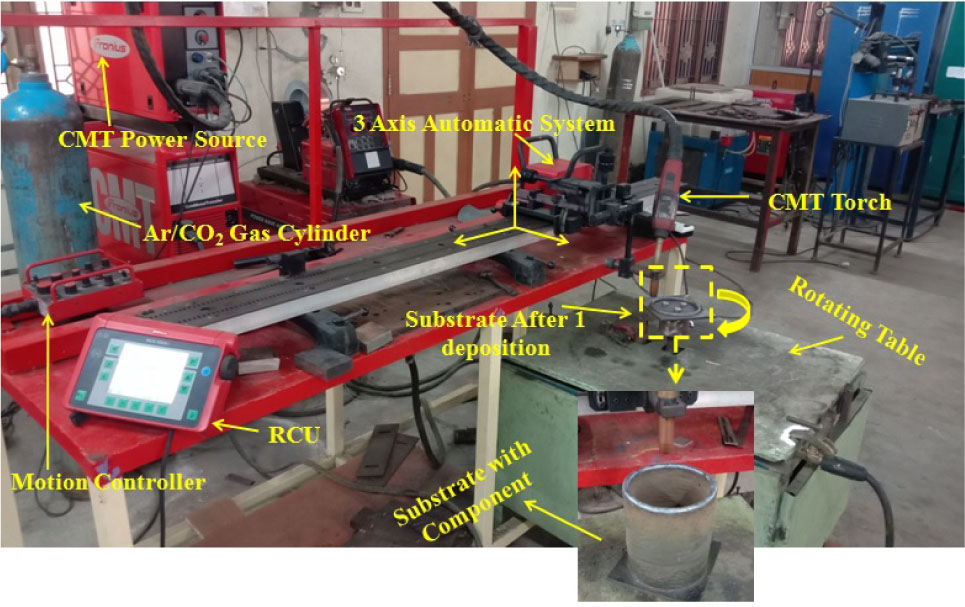
GMAW-WAAM platform used for fabrication.
GMAW-WAAM process parameters used to fabricate the component.
| Parameters | Value |
|---|---|
| Wire feed speed (m/min) | 6.7 |
| Current (A) | 227 |
| Voltage (v) | 18.3 |
| Travel speed (mm/min) | 400 |
| 85Ar+15CO2 (lpm) | 15 |
The one-pass deposition has a width of 7.8±2 mm and a height of 2.2 mm. A pause of 120 s was imposed between each layer deposition, in order to enable a partial cooling of the deposited material. The welding wire extended 15 mm from the nozzle (contact tip to workpiece distance). The used WAAM platform, the fabricated wall, and its graphical representation are shown in Figure 2. The measurements of the fabricated cylindrical component, including the thickness, height and diameter were presented in Table 4. The diameter, height of manufactured cylindrical component was about 127 mm and 160 mm, respectively. Figure 3 shows fabricated cylindrical wall component side view a) and top view b). Following the fabrication process, the deposited material (5 mm) removed at the end of component. The base plate with deposited material (5 mm) was removed from the built component to prevent the effect of dilution on mechanical and microstructural characteristics. The fabricated component was separated to in two regions: Bottom region (from substrate to 75mm height) and Top region (from 75 mm to end of component) and schematically shown in Figure 2. The fabricated component was machined by a CNC lathe and specimens were extracted by an automatic shaper machine. The component was machined to inspect the quality of depositions. The fabricated cylinder wall is free from macro level defects and cracks. The photographs of the machined cylindrical components (with 4 mm wall thickness) are displayed in Figure 4.
Dimensions of manufactured cylindrical component.
| Geometry | Unit | Value |
|---|---|---|
| Average wall thickness | mm | 7.8±2 |
| Average single layer height | mm | 2.20 |
| Diameter of cylindrical component | mm | 127±7 |
| Number of deposited layers | — | 73 |
| Height of cylindrical component | mm | 160 |

Schematic illustration of the steel cylindrical component a) indicating direction of deposition, b) showing separation of component in two regions (b-1(bottom region) and b-2(top region)) and c). extraction of samples from two regions.

Photograph of the Low carbon steel straight cylindrical component (as fabricated) a) side view and b) top view.

Photograph of low carbon steel cylindrical component (after machining), a) side view, b) top view and c) showing wall thickness.
2.2 Mechanical properties evaluation
Figure 5 a) and b) show the dimensions of the smooth and notch tensile specimens. As per ASTM E8M standard, the tensile testing was done using a 50 kN servo controlled testing system (H50KL). At room temperature, the tensile tests were done and the transverse head displacement speed was 2 mm/min. In the 0.2 % offset methodology, the yield strength was determined from the engineering stress curve. The strain was calculated from a gauge length of 25 mm. Three specimens were tested from each region and the average value was reported for analysis purpose. The charpy impact specimens were tested using pendulum type Impact Testing Machine (Make & Model: FIE-BLUE STAR, India & 1E-IT-30(ASTM)). The charpy impact samples were prepared as per ASTM A370 sub-size standard and dimensions are shown in Figure 5 c). Three impact specimens were tested from top region and bottom region and the average of three was reported for analysis purpose. The tested tensile and impact specimen fracture surfaces were analyzed by scanning electron microscopy (model: JSM 6610LV). Microhardness was measured as per the procedure prescribed by ASTM E384-17 standard on the fine polished surface of the metallographic samples with a testing load of 500 gms and 15 s dwell time. Vickers Microhardness Testing Machine (SHIMADZU HMV-2T) was used to record microhardness at different regions and along the building direction.

Dimensions of Test Specimens a) smooth tensile specimen, b) notch tensile specimen and c) impact toughness specimen.
2.3 Macrostructure and microstructural characterization
The microstructural analysis was carried out at the center portion of top region and bottom region of the mirror polished microstructure samples etched by 2% Nital reagent. In order to examine the macrostructure of the manufactured component, the stereozoom microscope was used. The etched metallographic samples were then analysed under an optical microscope (MIL-7100) and the microstructure was recorded at different magnifications.
3 Results and discussion
3.1 Tensile properties
The tensile properties of the fabricated cylindrical component evaluated at different regions (top and bottom) are presented in Table 5. The tensile properties of two regions are lower than the filler metal (all weld metal). Figure 6 a) and b) show the image of notch and smooth tensile specimens after testing. From the tensile test results, it was found that the average values of yield strength (YS) and ultimate tensile strength (UTS) in the bottom region was lower than the top region. The mean values of YS and UTS of the specimens extracted from bottom region are 333 MPa and 429 MPa, respectively, whereas the average values of YS and UTS of specimens extracted from top region are 350 MPa and 446 MPa. Stress-strain curves of the top and bottom region samples are shown in Figure 7. The samples extracted from top region showed higher strength with lower elongation than bottom region. It is due to the heterogeneous microstructure of deposited cylindrical wall. The notch tensile strength (NTS) and notch strength ratio (NSR) are determined by performing a tensile test on notch tensile specimens. The notch strength ratio (NSR) was calculated using the Eq. (1).
Tensile and impact toughness properties of cylindrical component.
| Region | UTS (MPa) | 0.2% YS (MPa) | Elongation (%) | NTS (MPa) | NSR (%) | Impact Toughness at RT (J) |
|---|---|---|---|---|---|---|
| Bottom Region | 429 | 333 | 57.13 | 574 | 1.33 | 69 |
| Top Region | 446 | 350 | 53.6 | 589 | 1.32 | 62 |

The photographs of the tested specimens, a) smooth tensile specimens, b) notch tensile specimens and c) impact toughness specimens.

Stress–strain curves of the tensile specimen.
It is observed that the top region samples were showed maximum NTS of 589 MPa than bottom region. The NSR is more than one in all samples. It suggests that the samples under the class of ductile and are less susceptible to notches. So, the GMAW-WAAM cylindrical wall components are ductile in nature.
3.2 Impact toughness
Table 5 shows the impact toughness in bottom and top regions of GMAW-WAAM cylindrical component. The photograph of the impact specimens after testing is shown in the Figure 6 c). The impact toughness of cylindrical wall component decreased from bottom region to top region. The impact toughness values were opposite to the tensile properties of bottom region and top region. It is observed that the bottom region samples were recorded highest impact toughness of 69 J, which is higher than top region. It is due to the variation in ductility of top region and bottom region. The variation in ductility is common in WAAM components along the building direction. The variation in ductility is mainly due to the different type of microstructures formed in two regions. In comparison with ER70S-6 filler metal, the value of the impact toughness of deposited weld metal is lower.
3.3 Microhardness survey
The Vickers microhardness variation in the deposited component from the bottom to the top region along the vertical direction is shown in Figure 8. The overall average micro-hardness was 161 ± 3 (Hv0.5) across the entire component, with minimal fluctuation in the building direction due to changes in the microstructure. The evenly distributed microhardness values have a minor deviation (± 3 Hv0.5) from the average microhardness value (161 HV), attributed to the presence of various micro-constituents as described in the microstructure characterization section. The average microhardness values are taken in center portion of bottom and top regions presented in Table 6. The highest value of microhardness (166 Hv0.5) was recorded in the top region and bottom region recorded the lowest value of microhardness (157 Hv0.5). The difference in microhardness is due to the different microstructures evolved in top region and bottom region.

Vickers microhardness variations on the surface of the component along the building direction.
Average microhardness of cylindrical component.
| Region | Microhardness(Hv0.5) |
|---|---|
| Bottom Region | 157 |
| Top Region | 166 |
3.4 Macrostructure and microstructural characterization
The macrostructure analysis was done on the specimen extracted from center portion of the top region and bottom region of cylinder component. Figure 9 a) and b) show the macrostructure images of bottom and top regions, respectively. The different 3 weld layers are clearly visible in the macro photographs and the photographs show the weld beads are free from major level defects and cracks and the layers are properly fused together. The macro photograph shows that the weld is free from cracks and other visual defects.

Macrostructures of the cylindrical component a) bottom region and b) top region.
Figure 10 a) displays the microstructure of the cylindrical component. From the micrograph, it is confirmed the presence of pearlite in ferrite matrix. The white regions are ferrite and dark areas are pearlite formed with in the grain at boundaries. The microstructure of two regions is the as-built cylindrical component is shown in Figure 10 b), c) and d). It is clear that the microstructure of the top region significantly differs from the microstructure of the bottom region. In fact, the cylindrical component of bottom region was characterized by almost equivalent microstructure, while the lamellar structures were observed in top region. The bottom region micrograph is shown in Figure 10 b). The bottom region is made of pure ferrite with roughly equal grains. Given the initial thermal shock caused by contact with the substrate, it is possible to see in the micrograph that this microstructure is characterized by complete ferrite grains. In Figure 10 c), the top region revealed the lamellar structures composed with polygonal ferrite (PF), as well as three kinds of ferrite grains: ferrite side plates with real plate like structures (αw), the presence of brittle pearlite structures along the boundaries (GBF), and αa shown in Figure 10 d). It is due to the effect of the constant cooling of the natural air and heat transfer toward the bottom of the built component.

Optical micrographs of WAAM component, a) primary microstructure of ER70S-6, b) in bottom region, c) in top region with lower magnification and d) in top region in higher magnification.
3.5 Fractography
Figure 11 and 12 show the fractographs of the bottom and top regions of smooth, notch and impact specimens at different magnifications. In response to fracture, all of the tensile and impact specimens had a ductile morphology with many deep and elongated dimples. There is no major difference in the fracture characteristics of all the specimens that have been taken from different regions (bottom and top). However, the fracture surface of the smooth tensile specimen differs from the bottom to the top region. The fracture surface of the top region specimen presents small micro voids, cleavage faces indicated in Figure 12 b). Figure 12 c) shows the high magnification image of the smooth tensile fracture surface of the top region. The top region of the smooth tensile fracture surface consists of small dimples, indicating that the fracture is ductile. The high strength and lower elongation are due to the fine dimples of the top region of the WAAM carbon steel cylindrical component. Similarly, the bottom region of the smooth tensile specimen presents large dimples indicating that the fracture is ductile in Figure 11 b). Figure 11 c) shows the high magnification image of the smooth tensile fracture surface of the bottom region. The bottom region of the smooth tensile fracture surface consists of more elongated dimples compared to the top region due to the microvoid coalescence effect. The high ductility is due to the more elongated dimples in the bottom region of the manufactured cylindrical component. Similar behaviour was observed by Zidong Lin et al. [17] in GMAW based WAAM medium carbon steel parts. The tensile strength of the horizontal sample showed high strength and lower elongation due to fine dimples, and more elongation and low strength was observed in vertical direction samples due to more elongated large dimples. The author concluded that the dimple size in the horizontal samples was smaller compared to the vertical samples due to the micro-void coalescence effect.

SEM fractographs of the specimen extracted from bottom region, (a–c) smooth tensile, (d–f) notch tensile and (g–i) charpy impact.

SEM fractographs of the specimen extracted from top region tested specimens, (a–c) smooth tensile, (d–f) notch tensile and (g–i) charpy impact.
The fracture surfaces of the bottom and top regions of the notch tensile specimens present cleavage and dimples as indicated in Figure 11 and 12. Hence, the mode of failure of the notch tensile specimens happens in a qausi-cleavage mode regardless of regions (bottom and top) similar to the results reported by Addanki Ramaswamy et al. [18]. The author observed that both cleavage and dimples had minor voids in the tested notch tensile samples.
Figure 11 (g–i) and 12 (g–i) show the fracture surfaces of the bottom and top regions of impact specimens. The top region of the tested impact specimen presents dimples with cleavage faces and dimples with small secondary cracks are formed in the bottom region of the manufactured carbon steel cylindrical component. All the impact specimens present ductile morphology with dimples in response to fracture. The high toughness in the bottom region of the component is due to the shallower dimples with secondary cracks. The creation and motion of dislocations in the crystal lattice are responsible for the plastic deformation. The component dissipates energy during the dislocation movements and crack tip dislocation leads to intrinsic ductility. So, the secondary cracks act as a crack divider impact loading [19].
3.6 Discussion
The stress versus strain curves recorded during tensile testing of the specimens extracted from the two regions (bottom and top) of the cylindrical components made by GMAW-WAAM are depicted in Figure 7. Additionally, Table. 4 presents the extracted tensile properties, including the YS and UTS of WAAAM cylindrical component along building direction in two regions. The average values of YS and UTS showed small difference, but not so much. Similarly Sridharan N et al. [11] also observed changes in YS and UTS along the horizontal and vertical direction of WAAM steel part. Figure 7 clearly shows that the elongation was reduced in the top region than the bottom region, confirming the change in ductility. In WAAM components, the change in ductility along the building direction is common. [20]. Beth E. Caroll et al. fabricated Ti-6Al-4V linear wall part by direct energy deposition technique. The author stated that the enhancement in ductility is partially due to the absence of pores in the component, and the presence of grain boundary α leading to fracture and responsible for the anisotropy in ductility. The change in the tensile strength of the bottom and top region samples is mostly attributed by the heterogeneous of the microstructure, as confirmed by the different microhardness values from the bottom region to the top region of the WAAM-ER70S-6 cylindrical component.
On the other hand, the reduction in the toughness from the bottom region to the top region is due to the formation of brittle αw, GBF and PF in top region. Due to hard phase of αw, GBF and PF, the hardness was increased in top region is one of the reasons for higher strength also; due to high rate of cooling in top region, it causes the microstructural transformation from austenite to αw and GBF. Haselhuhn et al. [21] documented that the change of PF to αw is due to the change in cooling rate from the center of melt pool to melt pool boundaries in a WAAM-ER70S-6 wall resulted in variation in tensile properties and hardness along the building direction. The differences observed in the microstructures are due to the variations in thermal history experienced by the multiple welding beads deposited, in which the top region is affected by the stronger thermal shock.
Wilson Heid et al. [22] observed the relation between change in ductility and microstructure of WAAM-Ti-6Al-4V alloy and reported that the% of elongation was higher in deposition direction than in building direction. In the WAAM Ti-6Al-4V alloy, Wang et al. [23] also observed the anisotropic in mechanical properties, showing high ductility and low strength in building direction than in the horizontal direction. The authors reported that the difference in columnar growth of Ti grains during solidification might be reason for variation in mechanical properties along deposition direction and building direction. The highest toughness was observed in bottom region, PF occurred in the form of coarse ferrite islands inside the prior austenite grains in top region. The presence of brittle pearlite structures along grain boundaries is often referred to as GBF and ferrite side plates are also referred to as was αw were detrimental to toughness with its coarse grain structure in top region. Similar behaviour was observed Salimi A et al. [24] in banded steel structures. The author documented the change in impact toughness in the deposition direction and the building direction as a result of the built part's heterogeneous microstructures.
4 Conclusions
In this study, low-carbon steel cylindrical component was additively manufactured utilizing GMAW-WAAM technique. Microstructure and mechanical properties of the manufactured component were characterized in two different regions (bottom and top) along building direction. The following important conclusions are drawn from this study:
The GMAW-WAAM process allows building low carbon steel cylindrical component with high density and without major defects such as cracks and improper fusions between adjacent layers. The macro photographs show the weld beads are free from defects, cracks and other visual defects and the layers are properly fused together.
The top region of cylindrical component made by GMAW-WAAM technique exhibited higher ultimate tensile strength, yield strength and higher hardness than bottom region due to formation of αw and GBF. This may be one of the reasons for higher hardness and detrimental to toughness of the top region.
The microstructure of the built cylindrical component varies from the bottom to the top and can be distinguished in two regions, i.e., lamellar structures (αw, GBF and αa) in the top region; and equiaxed grains of fully ferrite in the bottom region.
Acknowledgement
The first author is grateful to the Department of Science and Technology (DST), Ministry of Science and Technology, Government of India, New Delhi for the financial support rendered through Fellowship under PURSE-Phase-2 scheme. The authors wish to record sincere thanks to M/s. Fronius India Pvt. Limited, Chennai for technical support.
References
[1] Liberini M, Astarita A, Campatelli G, Scippa A, Montevecchi F, Venturini G, Massimo D, Boccarusso L, Minutola FMC, Squillace A, et.al. Selection of optimal process parameters for wire arc additive manufacturing. Procedia CIRP. 2017; 62:470–474.10.1016/j.procir.2016.06.124Search in Google Scholar
[2] Xiong J, Zhang G, et.al. Adaptive control of deposited height in GMAW-based layer additive manufacturing. Journal of Materials Processing Technology. 2014; 214(4):962–968.10.1016/j.jmatprotec.2013.11.014Search in Google Scholar
[3] Bekker ACM, Verlinden JC, et.al. Life cycle assessment of wire + arc additive manufacturing compared to green sand casting and CNC milling in stainless steel. Journal of Cleaner Production. 2018; 177:438–447.10.1016/j.jclepro.2017.12.148Search in Google Scholar
[4] Ding D, Pan Z, Cuiuri D, Li H, et.al. A multi-bead overlapping model for robotic wire and arc additive manufacturing (WAAM). Robotics and Computer-Integrated Manufacturing. 2015; 31:101–110.10.1016/j.rcim.2014.08.008Search in Google Scholar
[5] Williams S.W, Martina F, Addison A.C, Ding J, Pardal G, Colegrove P, et.al. Wire + Arc additive manufacturing. Materials Science Technology. 2016; 32(7):641–647.10.1179/1743284715Y.0000000073Search in Google Scholar
[6] Ding D, Pan Z, Cuiuri D, Li H, et.al. Wire-feed additive manufacturing of metal components: Technologies, developments and future interests. The International Journal of Advanced Manufacturing Technology. 2015; 81:465–481.10.1007/s00170-015-7077-3Search in Google Scholar
[7] Buchanan C, Gardner L, et.al. Metal 3D printing in construction: a review of methods, research, applications, opportunities and challenges. Engineering Structures. 2019; 180:332–348.10.1016/j.engstruct.2018.11.045Search in Google Scholar
[8] Pires JN, Loureiro A, Bölmsjo G. Welding robots: technology, system issues and application. 1st ed. Springer-Verlag London; 2006.Search in Google Scholar
[9] Zhang Z, Sun C, Xu X, Liu L, et.al. Surface quality and forming characteristics of thin-wall aluminium alloy parts manufactured by laser assisted MIG arc additive manufacturing. International Journal of Lightweight Materials and Manufacturing. 2018; 1(2):89–95.10.1016/j.ijlmm.2018.03.005Search in Google Scholar
[10] Mohandas T, Madhusudhan Reddy G, Satish Kumar B, et.al. Heat-affected zone softening in high-strength low-alloy steels. Journal of Materials Processing Technology. 1999; 88:284–294.10.1016/S0924-0136(98)00404-XSearch in Google Scholar
[11] Sridharan NS, Noakes MW, Nycz A, Love LJ, Dehoff RR, Babu SS, et.al. On the toughness scatter in low alloy C-Mn steel samples fabricated using wire arc additive manufacturing. Materials Science and Engineering: A. 2018; 713:18–27.10.1016/j.msea.2017.11.101Search in Google Scholar
[12] Li Y, Sun Y, Han Q, Zhang G, Horvath I, et.al. Enhanced beads overlapping model for wire and arc additive manufacturing of multi-layer multi-bead metallic parts. Journal of Materials Processing Technology. 2018; 252:838–848.10.1016/j.jmatprotec.2017.10.017Search in Google Scholar
[13] Xiong J, Li Y, Li R, Yin Z, et.al. Influences of process parameters on surface roughness of multi-layer single-pass thin-walled parts in GMAW-based additive manufacturing. Journal of Materials Processing Technology. 2018; 252: 128–136.10.1016/j.jmatprotec.2017.09.020Search in Google Scholar
[14] Yang D, Wang G, Zhang G, et.al. Thermal analysis for single pass multi-layer GMAW based additive manufacturing using infrared thermography. Journal of Materials Processing Technology. 2017; 244:215–224.10.1016/j.jmatprotec.2017.01.024Search in Google Scholar
[15] Zhao H, Zhang G, Yin Z, Wu L, et.al. Effects of interpass idle time on thermal stresses in multipass multilayer weld-based rapid prototyping. Journal of Manufacturing Science and Engineering. 2013; 135(1):011–016.10.1115/1.4023363Search in Google Scholar
[16] Gokhale NP, Kala P, Sharma V, et.al. Thin-walled metal deposition with GTAW welding-based additive manufacturing process. Journal of the Brazilian Society of Mechanical Sciences and Engineering. 2019; 41:569.10.1007/s40430-019-2078-zSearch in Google Scholar
[17] Lin Z, Goulas C, Ya W, Hermans M, et.al. Microstructure and Mechanical Properties of Medium Carbon Steel Deposits Obtained via Wire and Arc Additive Manufacturing Using Metal-Cored Wire. Metals. 2019; 9(6):673.10.3390/met9060673Search in Google Scholar
[18] Ramaswamy A, Malarvizhi S, Balasubramanian V, et.al. Influence of post weld heat treatment on tensile properties of cold metal transferred arc welded AA6061-T6 aluminium alloy joints. Journal of Mechanical Behavior of Materials. 2020; 28:135–145.10.1515/jmbm-2019-0015Search in Google Scholar
[19] Kysar, J.W, et.al. Energy dissipation mechanisms in ductile fracture. Journal of the Mechanics and Physics of Solids. 2003; 51: 795–824.10.1016/S0022-5096(02)00141-2Search in Google Scholar
[20] Carroll BE, Palmer TA, Beese AM, et.al. Anisotropic tensile behavior of Ti-6Al-4V components fabricated with directed energy deposition additive manufacturing. Acta Materialia. 2015; 87:309–320.10.1016/j.actamat.2014.12.054Search in Google Scholar
[21] Haselhuhn AS, Wijnen B, Anzalone GC, Sanders PG, Pearce JM, et.al. In situ formation of substrate release mechanisms for gas metal arc weld metal 3-D printing. Journal of Materials Processing Technology. 2015; 226:50–59.10.1016/j.jmatprotec.2015.06.038Search in Google Scholar
[22] Wilson-Heid AE, Wang Z, McCornac B, Beese AM, et.al. Quantitative relationship between anisotropic strain to failure and grain morphology in additively manufactured Ti-6Al-4V. Materials Science and Engineering A. 2017; 706:287–294.10.1016/j.msea.2017.09.017Search in Google Scholar
[23] Wang F, Williams S, Colegrove P, et.al. Antonysamy AA, Microstructure and mechanical properties of wire and arc additive manufactured Ti-6Al-4V. Metallurgical and Materials Transactions A. 2013; 44:968–977.10.1007/s11661-012-1444-6Search in Google Scholar
[24] Salimi A, Zadeh M, Toroghinejad M, Asefi D, Ansaripour A, et.al. Influence of sample direction on the impact toughness of the api-x42 microalloyed steel with a banded structure. Materiali in Tehnologije. 2013; 47(3):385–389.Search in Google Scholar
© 2021 Bellamkonda Prasanna Nagasai et al., published by De Gruyter
This work is licensed under the Creative Commons Attribution 4.0 International License.
Articles in the same Issue
- Research Articles
- The elastic-plastic properties of an anti-icing coating on an aluminum alloy: Experimental and numerical approach
- Optimization of recycled slag-fresh flux mixture based upon weld bead quality for submerged arc welding of stainless steel
- Design and optimization of differential capacitive micro accelerometer for vibration measurement
- Mechanical performance of abrasive sandpaper made with palm kernel shells and coconut shells
- Experimental investigation of WEDM process through integrated desirability and machine learning technique on implant material
- Mechanical properties and microstructural characteristics of rotating arc-gas metal arc welded carbon steel joints
- Assessment of cement replacement with fine recycled rubber particles in sustainable cementitious composites
- Structural response and sensitivity analysis of granular and asphaltic overlayment track considering linear viscoelastic behavior of asphalt
- Unmanned aerial vehicle evasion manoeuvres from enemy aircraft attack
- Effect of corrosion on surface degradation of galvanized steel in poultry dung, pig dung and urea solutions using rice straw as an inhibitor
- Mathematical modeling of AZ30 magnesium alloys at high temperature using the ring compression test and genetic algorithm method
- Study on hot deformation behavior and workability of stir-cast Al6063-6wt.% steelp based composites
- The effects of processing parameters on the formation of oxide layers in aluminium alloys using plasma electrolytic oxidation technique
- Behavior of green reactive powder mortar reinforced with steel fibers
- On the hygrothermal properties of sandcrete blocks produced with sawdust as partial replacement of sand
- Mechanical behavior of thin-walled steel under hard contact with rigid seabed rock: Theoretical contact approach and nonlinear FE calculation
- Mechanical properties and microstructural characteristics of rotary friction welded dissimilar joints of rolled homogeneous armor steel and medium carbon steel
- Studies of carboxylated nitrile butadiene rubber/butyl reclaimed rubber (XNBR/BRR) blends for shoe soles application
- Mechanical properties of wire arc additive manufactured carbon steel cylindrical component made by gas metal arc welding process
- Synthesis and mechanical characterization of Si3N4 reinforced copper-tin matrix composites
- Analysis of plated-hull structure strength against hydrostatic and hydrodynamic loads: A case study of 600 TEU container ships
- Mechanical performance investigation of lignocellulosic coconut and pomegranate / LDPE biocomposite green materials
- Special Issue MICAP-2021
- Double hydrothermal synthesis of iron oxide/silver oxide nanocomposites with antibacterial activity**
- Enhanced photocatalytic activity of TiO2-CdS composite nanofibers under sunlight irradiation**
- Structural properties of CoxCu1−xFe2O4 solid solution**
- Green-synthesis of Ag2O nanoparticles for antimicrobial assays**
- Effect of current density on the porous silicon preparation as gas sensors**
- A mechanochemical preparation, properties and kinetic study of kaolin–N, P fertilizers for agricultural applications**
- Impact strength of surface treated SS316L wires reinforced PMMA**
- Computational studies on electronic and optical properties of dopamine derivatives structure: A DFT study**
- Multilayer coating effects on the thermal conductivity of tools using an electric furnace technique**
- The positron and mechanical parameters of a cold-worked aluminum alloy (3004) Using PALT, PADBT and HV**
- Effect of thermal annealing on the structural and optical properties of TiO2 nanostructures**
- Improvement of forging die life by failure mechanism analysis**