Structural response and sensitivity analysis of granular and asphaltic overlayment track considering linear viscoelastic behavior of asphalt
-
Dian M. Setiawan


Abstract
This study investigated the structural response of granular and asphaltic overlayment of rail track considering the linear viscoelastic behavior of asphalt. The calculation of the tensile strains at the bottom of the asphalt layer, the compressive stresses at the top of the subgrade layer, and the service life of the granular and the asphaltic overlayment rail track were conducted using the KENTRACK software. Furthermore, the sensitivity analysis by changing different factors was studied in this paper. The results of this study indicate that the asphaltic overlayment rail track structure has a much longer predicted service life than the granular rail track. It was also shown that the sub-grade compressive stress is more sensitive to the change in subgrade modulus than the change in ballast-sub-ballast-asphalt layer thickness and the change in binder type, respectively. In addition, the asphalt tensile strain is more sensitive to the change in asphalt layer thickness than the change in subgrade modulus and the change in binder type, respectively. These findings also enhance our understanding that subgrade compressive stress and asphalt tensile strain in the asphaltic overlayment track are more sensitive to the change in asphalt layer thickness than the change in binder type.
1 Introduction
1.1 Granular trackbed
The service life of a rail track design is its period of use in service. It is known that the ballast layer may encounter a failure in mechanical and geometrical performances caused by environmental loads and heavy train [1, 2]. Besides, the poor ballast and sub-ballast material performance could be a benchmark consideration for the needs of maintenance work, the determination of track quality index [3], as well as the application of train speed restrictions [4]. The conventional track may experience higher ballast deformations and track misalignments (Figure 1a). As can be seen in Figure 1b, the mud pumping is characterized by the fast upward migration of sub-soil fine particles through the ballast voids, and it has been known to be the worst degradation phenomenon for the railway sub-structure [5]. Moreover, due to soil subsidence and rainwater erosion, ballast material deficiency always occurs in the transition (Figure 2).

(a) Ballast deformation; (b) mud pumping.

Ballast material deficiency.
1.2 Asphalt rail track
According to Liu [6], there are two types of asphalt trackbed designs used in railway industry. One is called “underlayment” because the asphalt is applied as a sublayer or a mat between ballast and subgrade to replace sub-ballast. Due to the underlayment design’s ability to maintain the ballast within the structure so that the track geometry can be easily adjusted, therefore, the underlayment design is preferred by railroad engineers in the United States. Also, the asphalt layer is maintained in a protected environment because it is buried under the ballast, which provides protection, such as minimizing sunlight exposure and temperature variances. The second type is called “full depth” or “overlayment” because the asphalt layer is located directly on the subgrade. There is no ballast layer in asphalt overlayment rail track and the sleeper is located on the top of asphalt layer.
Several kinds of research have been conducted to create computer models that can design and analyze the railroad track-beds structure by utilizing the finite element system. ILLITRACK [7, 8], FEART [8, 9], and GEOTRACK [8, 10] are some of the examples. However, they are unable to analyze the behavior of asphalt track-beds and slab track-beds, and they can only be utilized for the analysis of granular rail track. Therefore, KENTRACK, a program that can analyze the stress distribution for both asphalt and granular rail track [8, 11, 12], was developed in the United States. It is interesting to note that originally KENTRACK considers the asphaltic underlayment rail track type where the asphalt layer is submerged and insulated by the thickness of the sleeper and ballast. Therefore, this paper will attempt to analyze the structural response of another asphalt trackbed design type, the asphaltic overlayment rail track, using KENTRACK program. The typical rail track structures evaluated in this paper are presented in Figure 3 and Figure 4. The granular railway track in Figure 3 contains ballast, sub-ballast, and subgrade layer, while the geometry of asphalt overlayment track structure in this paper adopted from Lee et. al. [13] as shown in Figure 4.
![Figure 3 All-granular trackbed [6].](/document/doi/10.1515/jmbm-2021-0008/asset/graphic/j_jmbm-2021-0008_fig_003.jpg)
All-granular trackbed [6].
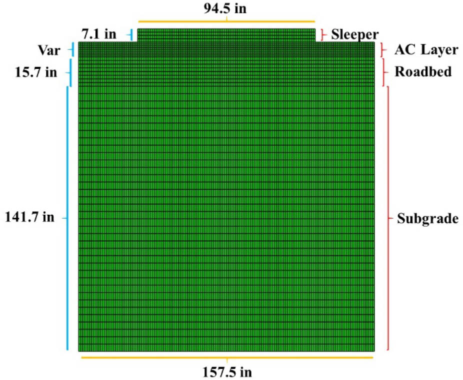
Asphaltic overlayment trackbed.
The objectives of this research are not only to calculate the tensile strains at the bottom of the asphalt layer and the compressive stresses at the top of the subgrade layer, but also to calculate the service life of the granular rail track and the asphaltic overlayment rail track using the KENTRACK software. Furthermore, sensitivity analysis by changing different factors, such as rail type, axle loads, load repetitions per year, modulus of subgrade, ballast and sub-ballast layer thickness, asphalt layer thickness, asphalt binder’s types on the mechanical behavior and design life of granular and asphaltic overlayment rail track are presented in this paper. The results of this research are beneficial for the railway industry. If the rail track engineer can construct a stronger and more long-lasting rail track structure, the government can operate the train with higher speed and axle load (more passengers and goods). At the same time, it will reduce maintenance costs and ensure passenger comfort and safety.
2 Research method
In order to evaluate the structural response of the granular and asphalt rail track, the KENTRACK software was utilized by considering the linear viscoelastic behavior of asphalt layer, non-linear elastic behavior of ballast and sub-ballast layer, and linear elastic behavior of subgrade. The Burmister’s multi-layer system was used to compute the stress and strain in each layer (Figure 5) while the FE method was utilized to compute the stress and strain in the rail and sleeper (Figure 6). The computation of Witczak E* predictive model was performed to check and to validate the data of Asphalt’s Young Modulus through season in KENTRACK.
![Figure 5 Burmister’s multi-layer system to compute stress and strain in each layer [6].](/document/doi/10.1515/jmbm-2021-0008/asset/graphic/j_jmbm-2021-0008_fig_005.jpg)
Burmister’s multi-layer system to compute stress and strain in each layer [6].
![Figure 6 Finite Element Method for the rail and sleepers stress-strain analysis [6].](/document/doi/10.1515/jmbm-2021-0008/asset/graphic/j_jmbm-2021-0008_fig_006.jpg)
Finite Element Method for the rail and sleepers stress-strain analysis [6].
The original development goal of KENTRACK 4.0 was to analyze the traditional all-granular rail track, asphalt underlayment rail track, and combination granular-asphalt rail track.
2.1 Climate and environmental effect
Temperature has a significant effect on the design and performance of both rigid and flexible pavement. Variations in temperature within a pavement structure contribute to pavement distress and possible failure in several ways [14]. KENTRACK considers 4 different seasons that will impact the material properties such as viscosity of the binder, elastic modulus of binder, and asphalt temperature through seasons. These 4 seasons were used to represents the season of Spring, Summer, Fall, and Winter.
2.2 Loads and number of repetitions
In order to assess the influence of the changes in the magnitudes of axle load on the structural response of the granular and asphaltic overlayment rail track, this research is considering three different axle loads as can be viewed in Table 1.
Axle loads and wheel loads.
| Load parameters | Lighter axle loads | Standard axle loads | Heavier axle loads |
|---|---|---|---|
| Wheel load in lbs | 30,000 | 36,000 | 42,000 |
| Wheel load in tons | 15 | 18 | 21 |
| Number of axle per car | 4 | 4 | 4 |
| Number of wheel per axle | 2 | 2 | 2 |
| Axle loads in tons | 30 | 36 | 42 |
| Total wheel loads per car in lbs | 240,000 | 288,000 | 336,000 |
| Total wheel loads per car in tons | 120 | 144 | 168 |
As can be seen in Figure 7, each car equals to one repetition. In order to measure the influence of the magnitude of load repetitions on the structural response of the granular and asphaltic overlayment rail track, therefore this research is considering three different magnitude of load repetitions per year as can be seen in Table 2. Although there should be a difference in the number of repetitions per year for each season, however, the distribution of the load repetitions is considered equal for each season for simplification reason.
![Figure 7 Two cars with 8 wheels for each car [6].](/document/doi/10.1515/jmbm-2021-0008/asset/graphic/j_jmbm-2021-0008_fig_007.jpg)
Two cars with 8 wheels for each car [6].
Load repetitions through seasons.
| Number of seasons considered per year | Lower load repetitions | Medium load repetitions | Higher load repetition |
|---|---|---|---|
| 4 | 125,000 | 250,000 | 500,000 |
| Total load repetitions per year | 500,000 | 1,000,000 | 2,000,000 |
2.3 Material properties
2.3.1 Rail
In order to assess the influence of the rail type on the structural response of the granular and asphaltic overlayment rail track, the default data of three different rail properties from KENTRACK was utilized in the analysis, as presented in Table 3.
Rail Properties of RE 115, RE 132, RE 140.
| Properties | RE 115 | RE 132 | RE 140 |
|---|---|---|---|
| Rail section modulus (in) | 18 | 22.5 | 24.6 |
| Rail soungs modulus (psi) | 30,000,000 | 30,000,000 | 30,000,000 |
| Rail moment of inertia (in4) | 65.6 | 88.2 | 96.8 |
| Rail sleeper spring xonstant (lb/in) | 7,000,000 | 7,000,000 | 7,000,000 |
2.3.2 Sleeper (tie)
This research used the default data of concrete sleeper (tie) from KENTRACK with the thickness of 7 in, width of 9 in, length of 108 in, moment of inertia of 257.25 in4, Youngs modulus of 4,220,598 psi, and sleeper’s spacing of 25.6 in. The track model that consists of rail, sleeper (tie), and layer systems are depicted in Figure 8.
![Figure 8 Trackbed model [6].](/document/doi/10.1515/jmbm-2021-0008/asset/graphic/j_jmbm-2021-0008_fig_008.jpg)
Trackbed model [6].
2.3.3 Linear viscoelastic behavior of asphalt layer
2.3.3.1 Superpave performance grade
Setiawan and Rosyidi [15], Setiawan et. al. [16], and Setiawan [17] have applied asphalt 60/70 penetration grade, which is commonly used in the construction of highway pavements in Indonesia as a ballast layer mixture component to increase elastic modulus and durability, and to reduce vertical deformation of ballast layer. Nowadays, a performance graded (PG) system replaces the asphalt binder grading based on viscosity and penetration. The PG specification uses several tests such as, creep stiffness, direct tension, and dynamic shear modulus to measure binder physical properties that related to the field performance. PG binders are tested under 3 states to represent 3 crucial states of the life of the binder, namely the transport and storage of the binder, production and construction of the mixture, and the long-term aging. For the long-term aging as the last stage, the binder is aged using a pressure aging vessel (PAV). The PAV exposes a sample to heat and pressure to simulate years of in-service asphalt aging. Therefore, by utilizing the PG system, asphalt test results can better simulate actual field situations, especially for the long-term aging [6].
Asphalt binders are graded based on their physical properties that directly explain how it will behave as a constituent in an asphalt mixture and it is strongly related to the binder viscosity, asphalt dynamic modulus, asphalt layer temperature through seasons, aggregate sizes, and gradation, and mix volumetric properties. Since it is based on climate, so the grade notation in the PG grading system consists of two parts, which are high and low service temperature. The main interest for high temperature performance is rutting, which normally takes time to develop. Hence, an average of 7-day maximum temperature of pavement is utilized to define the climate of high temperature. For the low temperature concern, thermal cracking can occur during one really cold night. Thus, the minimum pavement temperature suffered is utilized for depicting the climate of low temperature. PG grades are graded in increments of 6°F for both high and low temperature grades. The average 7-day maximum pavement temperature typically ranges from 46°F to 82°F, and minimum pavement temperature typically ranges from −46°F to −10°F. A binder identified as PG 70-28 should experience performance criteria at an average 7-day maximum pavement temperature of 70°F and at a minimum pavement temperature of −28°F [6].
In Liu [6], the asphalt layer was constructed below the ballast layer to replace the sub-ballast granular material and the design was considered as the asphaltic underlayment rail track type. Lee et. al. [13] developed another type of the rail track known as the asphaltic overlayment rail track type. The asphalt layer was divided into three sublayers, namely asphalt surface (Modified PG 76-22), intermediate (Conventional PG 64-22), and base layer (Conventional PG 64-22) using different aggregate sizes as previously completed by Lee et. al. [18]. Table 4 presents the asphalt layer properties in the asphaltic overlayment track developed by the Korean Railway Research Institute in Lee et. al. [13].
Asphalt layer properties of Korean Railway Research Institute’s track [13].
| Asphalt layer | % Passing 200, ρ200 (0.075 mm) | % Retained no. 4, ρ4 (4.75 mm) | % Retained no. 3/8, ρ38 (9.5 mm) | % Retained no. ¾, ρ34 (19 mm) | % Air voids, Va | % Volume of bitumen, Vbeff | Loading frequency, f (Hz) |
|---|---|---|---|---|---|---|---|
| AC – Surface | 5 | 38 | 9 | 0 | 3.14 | 5.6 | 1 |
| AC – Intermediate | 7 | 42 | 25 | 2 | 2.77 | 4.8 | 1 |
| AC – Base | 5 | 60 | 37 | 6 | 2.55 | 4.3 | 1 |
By using the same total of asphalt layer thickness as given in Lee et. al. [13], this paper also considers asphalt overlayment track but only consists of 1 asphalt layer for simplification reason. Asphalt layer properties used in this study was based on the AC-base layer in Table 4 where the % volume of bitumen is 4.3%. The variation of the asphalt layer in terms of binder grade is presented in Table 5. The objective was to assess the influence of asphalt binder grade on the subgrade compression stress and design life, as well as on the asphalt tensile strain and design life.
Variation of binder grade in asphaltic overlayment rail track.
| Layer | 1st Binder grade | 2nd Binder grade | 3rd Binder grade |
|---|---|---|---|
| Asphalt layer | PG 76-34 | PG 70-28 | PG 64-22 |
Table 6 shows the detail of asphalt binder viscosity (η, 106 Poise) for different seasons obtained from KENTRACK for each asphalt binder grade.
Viscosity of binder PG76-34, PG70-28, and PG64-22.
| Binder grade | Viscosity (η, 106 Poise) season 1 (spring) | Viscosity (η, 106 Poise) season 2 (summer) | Viscosity (η, 106 Poise) season 3 (fall) | Viscosity (η, 106 Poise) season 4 (winter) |
|---|---|---|---|---|
| PG 76-34 | 66.37 | 9.21 | 624.04 | 4264.55 |
| PG 70-28 | 135.20 | 13.07 | 1991.50 | 20617.93 |
| PG 64-22 | 253.18 | 16.60 | 6119.77 | 101304.76 |
Table 7 shows the asphalt layer temperature through seasons obtained from KENTRACK for each asphalt binder grade.
Asphalt layer temperature through seasons.
| Binder grade | Season 1 spring | Season 2 summer | Season 3 fall | Season 4 winter |
|---|---|---|---|---|
| PG 76-34 | 50 | 67 | 33 | 20 |
| PG 70-28 | 50 | 67 | 33 | 20 |
| PG 64-22 | 50 | 67 | 33 | 20 |
2.3.3.2 Method of viscosity temperature susceptibility (VTS)
In the predictive equation model, the viscosity is used to specify the shift factors and to describe the temperature effects. From the ASTM viscosity temperature relationship as Eq. (1) [19 in 6], the viscosity at the temperature of interest can be determined for un-aged binders.
With:
A and VTS – parameters of regression;
η – viscosity of binder, cP;
TR – temperature, Rankine.
Based on Garcia and Thompson [20] in Liu [6], this linear relationship allows a continuous binder viscosity description over a wide temperature range. It is categorized by its unique A and VTS parameters for the original condition of asphalt binder.
2.3.3.3 Asphalt’s dynamic complex modulus
In KENTRACK, the asphalt dynamic complex modulus was computed using the empirical Witczak E* predictive model. This model can predict mixture stiffness over a range of loading rate, temperatures, and aging conditions from information that is readily available from the mixture volumetric design or material specifications, as presented in Eq. (2). This model is able to estimate the mixture’s dynamic modulus by means of both conventional and modified asphalt binders [21, 22 in 6].
With:
|E*| – dynamic modulus (105 psi);
f – loading frequency (Hz);
η – binder viscosity at the age and temperature of interest (106 Poise);
Vbeff – effective binder content (% by volume);
Va – volume of air voids (%);
ρ200 – % passing #200 or 0.075mm sieve;
ρ4 – cumulative % retained on #4 or 4.76 mm sieve;
ρ38 – cumulative % retained on 3/8 in or 9.5 mm sieve;
ρ34 – cumulative % retained on 3/4 in or 19 mm sieve.
Dynamic complex modulus (E*) is one of the most essential asphalt properties used to measure the stiffness of viscoelastic materials and to examine asphalt layers responses in terms of stresses, strains, etc. The model is used to express the correlation between the dynamic modulus and loading rate based on a sigmoidal function. Mixtures volumetric properties, aggregate gradation, and binder rheological properties are addressed in the Witczak Predictive model. The model is good for the prediction of asphalt dynamic modulus because it has high accuracy [6]. Table 8 shows the detail of materials properties of asphaltic overlayment track in terms of Poisson’s ratio, assumed Youngs modulus, and asphalt dynamic modulus prediction through seasons.
Poisson’s ratio, assumed Youngs modulus, and Youngs modulus through seasons.
| Layer | Poisson’s ratio ν | Assumed Youngs modulus (psi) | 1st season, spring (psi) | 2nd season, summer (psi) | 3rd season, fall (psi) | 4th season, winter (psi) |
|---|---|---|---|---|---|---|
| Asphalt layer PG 76-34 | 0.35 | 3,900,000 | 1,286,595 | 739,909 | 2,141,969 | 3,017,040 |
| Asphalt layer PG 70-28 | 0.35 | 3,900,000 | 1,533,198 | 821,868 | 2,660,050 | 3,772,602 |
| Asphalt layer PG 64-22 | 0.35 | 3,900,000 | 1,770,827 | 881,507 | 3,189,218 | 4,521,217 |
| Roadbed | 0.2 | 26,000 | 26,000 | 26,000 | 26,000 | 26,000 |
2.3.4 Non-linear elastic behavior of ballast and sub-ballast
KENTRACK considers that the ballast layer behavior is nonlinear elastic (stress-dependency) for a new rail trackbed and is linear elastic for aged rail track since it is well compacted. The elastic modulus of nonlinear materials is established as Eq. 3 and Eq. 4 [12 in 6]:
With:
E = Resilient modulus;
K1, K2 = Regression constants reflecting material properties;
θ = Bulk stress, as the sum of 3 principal stresses including geostatic stresses.
A lateral stress ratio of K0 must be specified to compute the geostatic bulk stress. The material behaves linearly when K2 = 0. A constant Poisson’s ratio, independent of the stresses state, is expected for each layer because of its small effect on stress and strain [6]. Table 9 presents the material properties of ballast and sub-ballast layer used for granular rail track.
Properties of ballast and sub-ballast.
| Properties | Ballast | Sub-ballast |
|---|---|---|
| Poisson’s ratio ν | 0.35 | 0.35 |
| K2 | 0.5 | 0.5 |
| Elastic modulus (psi) | 20,000 | 18,000 |
| Unit weight (lb/in3) | 0.064 | 0.064 |
| Lateral Earth pressure (psi) | 0.8 | 0.8 |
2.3.5 Linear elastic behavior of subgrade
KENTRACK considers that the subgrade layer behavior is linear elastic both for a new rail trackbed and aged rail trackbed. Table 10 shows the material properties of sub-grade layer and its variation used to evaluate the effect of changes in subgrade quality on the subgrade compression stress and design life as well as on the asphalt tensile strain and design life.
Subgrade properties of granular and asphaltic overlayment rail track.
| Properties | Low subgrade quality | Medium subgrade quality | High subgrade quality |
|---|---|---|---|
| Poisson’s ratio ν | 0.4 | 0.4 | 0.4 |
| Elastic modulus (psi) | 6,000 | 12,000 | 18,000 |
| Unit weight (lb/in3) | 0.078 | 0.078 | 0.078 |
| Lateral Earth pressure (psi) | 0.5 | 0.5 | 0.5 |
2.4 Geometry and layer thicknesses
In order to evaluate the consequence of the changes in the granular layer thickness on the subgrade compression stress and design life, therefore this research is considering the thin, medium, and thick granular rail track as can be seen in Table 11.
Granular rail track geometry and layer thicknesses.
| Layer | Thin granular layer | Medium granular layer | Thick granular layer |
|---|---|---|---|
| Ballast (in) | 7.5 | 10 | 15 |
| Sub-ballast (in) | 3 | 4 | 6 |
| Subgrade (in) | Semi-infinite | Semi-infinite | Semi-infinite |
Moreover, there are also three different thicknesses of the asphaltic overlayment rail track that were investigated. The details are presented in Table 12.
Asphaltic overlayment track geometry and layer thickness.
| Layer | Thin asphalt layer | Medium asphalt layer | Thick asphalt layer |
|---|---|---|---|
| Asphalt (in) | 7.87 | 10.63 | 13.78 |
| Roadbed (in) | 15.75 | 15.75 | 15.75 |
| Subgrade (in) | Semi-infinite | Semi-infinite | Semi-infinite |
2.5 Damage analysis
In KENTRACK, the damage analysis for subgrade and asphalt layer within the track structure are based on periods and fatigue effects (cumulative damage criteria or damage equations) of repeated loading developed for highway pavements. The critical outputs of damage analysis performed in KENTRACK are horizontal tensile strain at the bottom of the asphalt layer and vertical compressive stress on top of the subgrade. The horizontal tensile strain controls fatigue cracking and the compressive stress controls excessive permanent deformation. Since this study considers the asphaltic overlayment rail track, therefore, the authentic service environment for the asphalt and subgrade in rail track environments are expected to be the same with highway pavements in terms of magnitudes of subgrade loading, sunlight exposure, and temperature fluctuations in the exposed trackbed environment.
The correlation between tensile strain and the allowable number of load repetitions in asphalt before failure is stated in Eq. (5) [23 in 6]:
With:
Na = Number of allowable load repetitions in asphalt;
Ea = Asphalt’s dynamic modulus, psi;
εt = Horizontal tensile strain at the bottom of asphalt.
The correlation between compressive stress and the allowable number of load repetitions in subgrade before failure is stated in Eq. (6) [12 in 6]:
With:
Nd = Number of allowable load repetitions in subgrade;
Es = Modulus of subgrade, psi;
σc = Compressive stress at the top of subgrade, psi.
The passage of one train’s car is equivalent to one load repetition. For example, if we have 1,000,000 load repetitions per year for 4 periods, it means that there are 1,000,000 train’s cars passing in the rail track through 4 periods per year. The predicted number of repetitions varies with the traffic that the rail track is subjected. With material properties and loading conditions differing throughout the year, damage may be assessed periodically or seasonally for one year to establish the structural design life. The number of allowable load repetitions during that period is gained from Eq. (5) and (6) for each mode of distress, according to the maximum stress or strain in each period. The repetition ratio, the ratio between the predicted and the allowable numbers of repetitions, is calculated for each period and summed to find the repetition ratio for the entire year. The design life is the reciprocal of the repetition ratio. If a year is divided into 4 seasons (spring, summer, fall, and winter), the service life for each distress mode can be expressed in Eq. (7):
With:
L = Service life in a specific layer (years);
n = Number of periods, 4 periods represent spring, summer, fall, and winter;
Np = Predicted number of load repetitions each season;
Nd = Number of allowable load repetitions in subgrade;
Na = Number of allowable load repetitions in asphalt.
3 Results and discuccion
In this study, two types of trackbeds are evaluated. The variation of the parameters is presented in Table 13.
Details of varied parameters in sensitivity analysis.
| LOAD | |||
| Axle load (tons) | 30 | 36 | 42 |
| Load repetitions per year | 500,000 | 1,000,000 | 2,000,000 |
| MATERIAL PROPERTIES | |||
| Rail type | RE 115 | RE 132 | RE 140 |
| Binder grade | PG 76-34 | PG 70-28 | PG 64-22 |
| Subgrade modulus (psi) | 6,000 | 12,000 | 18,000 |
| GEOMETRY | |||
| Ballast and sub-ballast thickness (in) | 7.5 + 3 | 10 + 4 | 15 + 6 |
| Asphalt thickness (in) | 7.87 | 10.63 | 13.78 |
3.1 Effect of rail type
In order to establish the rail strength and suitable axle loads, the unit weight of a rail per length is a crucial parameter. For heavier tonnages and wheel loads, larger rails are desirable. Three different rail type were used for the rail evaluation: RE 115, RE 132, and RE 140.
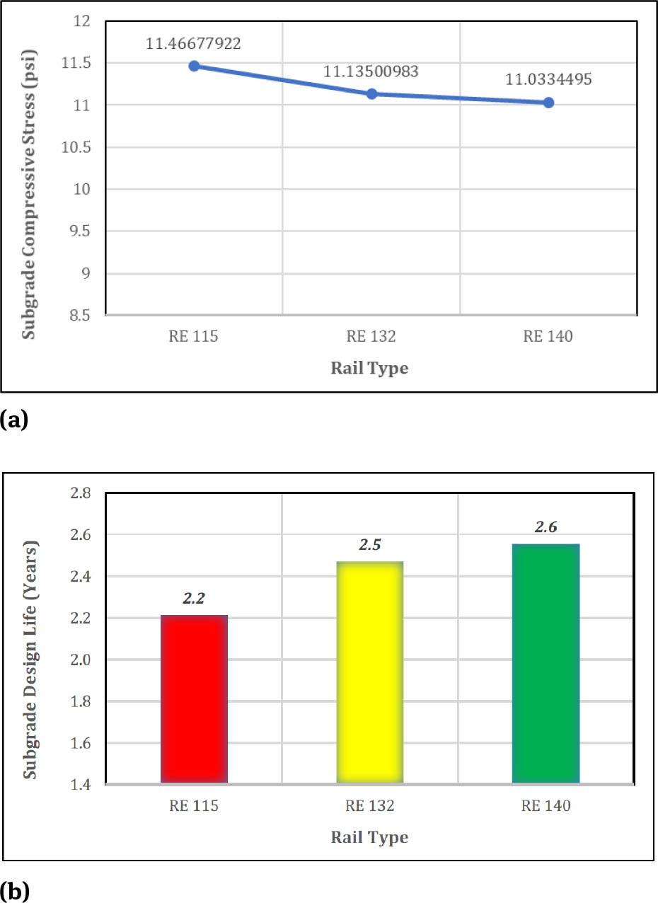
Figure 9 and 10 shows the effect of three different rail type on subgrade compressive stress (a) and subgrade service life (b) for the two types of rail track. Figure 11 presents the effect of varying rail type on asphalt tensile strain (a) and asphalt design life (b) in the asphalt overlayment rail track.
Effect of rail type on subgrade compressive stress (a) and on subgrade design life (b) in granular rail track.

Effect of rail type on subgrade compressive stress (a) and on subgrade design life (b) in asphaltic overlayment track.

a) Effect of rail type on asphalt tensile strain; b) effect of rail type on asphalt design life in the asphaltic overlayment rail track.
The rail types have a beneficial influence on the asphaltic underlayment rail track performance behavior. Heavier rails with larger sizes decrease subgrade compressive stresses and asphalt tensile strains, enhancing the design life, but only in the small percentage [6]. In granular rail track, the subgrade compressive stresses are reduced by 2.9% and 0.9% (Figure 9a), while the subgrade service lives are increased by 11.6% and 3.5% (Figure 9b) when the rail type is changed from RE 115 to RE 132 and from RE 132 to RE 140, respectively. In asphaltic overlayment rail track, the subgrade compressive stresses are reduced by 0.9% and 0.3% (Figure 10a), while the subgrade service life are increased by 1.3% and 0.5% (Figure 10b) when the rail type is changed from RE 115 to RE 132 and from RE 132 to RE 140, respectively. In addition, the asphalt tensile strains are reduced by 2.3% and 0.7% (Figure 11a), while the asphalt service lives are increased by 6.7% and 2.1% (Figure 11b) when the rail type is changed from RE 115 to RE 132 and from RE 132 to RE 140, respectively. Therefore, the change in the rail types still influence the service lives of granular and asphaltic overlayment rail track structure even though the effect is in the small portion, especially in the asphaltic overlayment track. Liu [6] also found that the rail type provides only small effect on the service life of asphaltic underlayment rail track.
3.2 Effect of axle load
In this research, three different axle loads were used to evaluate its effect on rail track’s stress-strain and structural design life.
Figure 12 and 13 shows the effect of three different axle loads on subgrade compressive stress (a) and subgrade design life (b) for the two types of rail track.

Axle loads effect on subgrade compressive stress (a) and on subgrade service life (b) in granular rail track.

Axle loads effect on subgrade compressive stress (a) and on subgrade service life (b) in asphaltic overlayment track.
Figure 14 presents the effect of varying axle loads on asphalt tensile strain (a) and asphalt design life (b) in the asphalt overlayment rail track. It is clear for the two rail track types that a larger magnitude of axle load could produce greater compressive stress on top of subgrade layer and greater asphalt tensile strain at the bottom of the asphalt layer due to large deformation of asphalt layers. As respected, large subgrade compressive stress and asphalt tensile strains decrease the service lives of the associated layers [6].

Axle loads effect on asphalt tensile strain (a) and on asphalt service life (b) in asphaltic overlayment rail track.
In granular rail track, the subgrade compressive stresses are increased by 19% and 16% (Figure 12a), while the subgrade service lives are reduced by 47% and 42% (Figure 12b) when the axle loads increase from 30 tons to 36 tons and from 36 tons to 42 tons, respectively. In asphalt overlayment rail track, the subgrade compressive stresses are increased by 20% and 17% (Figure 13a), while the sub-grade service life are reduced by 49% and 44% (Figure 13b) when the axle loads increase from 30 tons to 36 tons and from 36 tons to 42 tons, respectively. In addition, the asphalt tensile strains are increased by 20% and 17% (Figure 14a), while the service lives are decreased by 45% and 40% (Figure 14b) when the axle load increases from 30 tons to 36 enhances tons and from 36 tons to 42 tons, respectively.
Therefore, it can be concluded that axle loads possess a crucial effect on the design life of granular and asphaltic overlayment rail track. Heavy axle loads demand a resilient track base to support it due to growths in subgrade compressive stress and asphalt tensile strain. In addition, regulating the magnitude of axle load is advantageous for the rail track service life. Lastly, by utilizing the polynomial equation (R2 = 1) as can be seen in Figure 12, 13, and 14, we can predict the targeted subgrade and asphalt design life after determining the magnitude of axle loads.
3.3 Effect of load repetitions per year
Three different load repetitions were used to evaluate its effect on rail track’s stress-strain and structural design life. Figure 15 and Figure 16 shows the effect of three different load repetitions on subgrade service life for the two types of rail track. Figure 17 presents the Influence of varying load repetitions on asphalt design life in the asphalt overlayment rail track. Consider granular rail track, the subgrade design life is reduced by 50% and 50% (Figure 15) when the load repetitions per year increase from 500,000 to 1,000,000 and 1,000,000 to 2,000,000, respectively. Consider in an asphalt overlayment rail track, both the subgrade service life and asphalt service life are reduced by 50% and 50% (Figure 16 and Figure 17) when the load repetitions per year increase from 500,000 to 1,000,000 and 1,000,000 to 2,000,000, respectively.

Influence of load repetitions on subgrade service life in granular rail track.

Influence of load repetitions on subgrade service life in asphaltic overlayment track.

Influence of load repetitions on asphalt service life in asphaltic overlayment rail track.
Therefore, like the axle loads, the load repetitions also possess a crucial influence on the design life of rail track structure. High load repetitions demand a resilient track base to support it. Regulating the magnitude of load repetitions is also advantageous for the rail track design life. Furthermore, by using polynomial equation (R2 = 1) as can be seen in Figure 15, 16, and 17, we can predict the targeted subgrade and asphalt design life after determining the magnitude of load repetitions.
3.4 Effect of asphalt binder types
Three different binder types were used to evaluate its effects on rail track’s stress-strain and design life. According to Liu [6], the upper grade is principally counted for rutting, and it symbolizes the highest temperature in which the binder can manage. On the other hand, the lower grade is primarily counted for thermal cracking, and it symbolizes the lowest temperature a binder can manage. Therefore, it is predictable that, with the same number of asphalt layer temperature through seasons provided by KENTRACK, the stiffness of PG 64-22 binder grade is higher than PG 76-34 binder grade (Tables 7 and 8). As presented in Figure 18, for example at low temperatures during winter, PG 64-22 binder grade yielded highest E* values, followed by PG 70-28 and PG 76-34 binder grade.

E* through seasons for different binder type.
Figure 19 shows the effect of three different binder types on subgrade compressive stress and subgrade service life in the asphaltic overlayment rail track.

Effect of binder type on subgrade compressive stress (a) and on subgrade design life (b) in asphaltic overlayment tTrack.
Figure 20 presents the effect of varying binder type on asphalt tensile strain and asphalt design life in the asphalt overlayment rail track. Consider in an asphalt overlayment rail track, the subgrade compressive stresses are decreased by 1.3% and 0.9% (Figure 19a), while the subgrade service life are increased by the same magnitude (±10%), around 2 years (Figure 19b) when the binder grade change from PG 76-34 to PG 70-28 and from PG 70-28 to PG 64-22, respectively. In addition, the asphalt tensile strains are reduced by 2.4% and 2.0% (Figure 20a), while the asphalt service lives are increased by the same magnitude (±8.5%), around 0.6 years (Figure 20b) when the binder grade change from PG 76-34 to PG 70-28 and from PG 70-28 to PG 64-22, respectively. Therefore, the change in the binder types influence the service lives of asphaltic overlayment rail track structure even though the effect is in the small portion.

Effect of binder type on asphalt tensile strain (a) and on asphalt service life (b) in asphaltic overlayment rail track.
3.5 Effect of ballast and sub-ballast thickness and asphalt thickness
Figure 21 shows the effect of three different ballast-sub-ballast thickness on subgrade compressive stress and sub-grade service life in the granular rail track. Figure 22 shows the influence of three different asphalt thickness on sub-grade compressive stress and subgrade design life in the asphaltic overlayment rail track. Figure 23 presents the effect of asphalt thickness variation on asphalt tensile strain and asphalt design life in the asphalt overlayment rail track.

Influence of ballast and sub-ballast thickness on subgrade compressive stress (a) and on subgrade design life (b) in granular rail track.

Influence of asphalt thickness on subgrade compressive stress (a) and on subgrade service life (b) in asphaltic overlayment track.

Influence of asphalt thickness on asphalt tensile strain (a) and on asphalt service life (b) in asphaltic overlayment rail track.
It is clear for the two rail track types that a thicker layer results in lower compressive stress and lower tensile strain due to small deformation of asphalt layers. As respected, small subgrade compressive stress and asphalt tensile strains increase the design life of the associated layers.
Consider in granular rail track, the subgrade compressive stresses are decreased by 15.2% and 22.3% (Figure 21a), which could lead to significant enhance in subgrade design life by 85.3% and 156.2% (Figure 21b) when the ballast-sub-ballast thickness increase from 10.5 in to 14 in and from 14 in to 21 in, respectively. Consider in an asphalt overlayment rail track, the subgrade compressive stresses are reduced by 10.6% and 10.9% (Figure 22a), which could lead to significant enhance in the subgrade design life by 66% and 80.6% (Figure 22b) when the asphalt thickness increase from 7.87 in to 10.63 in and from 10.63 in to 13.78 in, respectively. In addition, the asphalt tensile strains are reduced by 9.1% and 18.1% (Figure 23a), while the service lives are increased significantly by 72.1% and 107.7% (Figure 23b) when the asphalt thickness increase from 7.87 in to 10.63 in and from 10.63 in to 13.78 in, respectively.
Ballast-sub-ballast thickness and asphalt thickness have a fundamental influence on the design life of granular and asphaltic overlayment rail track structure, respectively. Due to a thicker layer, then loads, stresses, and deformations have more space to distribute and transmit. It also can be observed for the same thickness of ballast-sub-ballast and asphalt layer, around 10.5 in, the subgrade compressive stresses in asphalt overlayment rail track is much lower than those in granular rail track.
Therefore, in this condition, it is obvious that asphaltic overlayment rail track provides higher capability in transmitting the loads and stresses from the top and reduces subgrade compressive stresses. It results in subgrade design life of 21.8 years (Figure 22), almost 17 times higher than the subgrade design life of granular rail track, which is only 1.3 years (Figure 21) for the same thickness of ballast-sub-ballast and asphalt layer (10.5 in). It is important to design an asphalt layer with the suitable thickness. Although a thick asphalt layer can increase the performance of the asphaltic overlayment rail track, however, it will increase costs. Therefore, a balance must be reached between the added cost and the performance improvements [6].
3.6 Effect of subgrade modulus
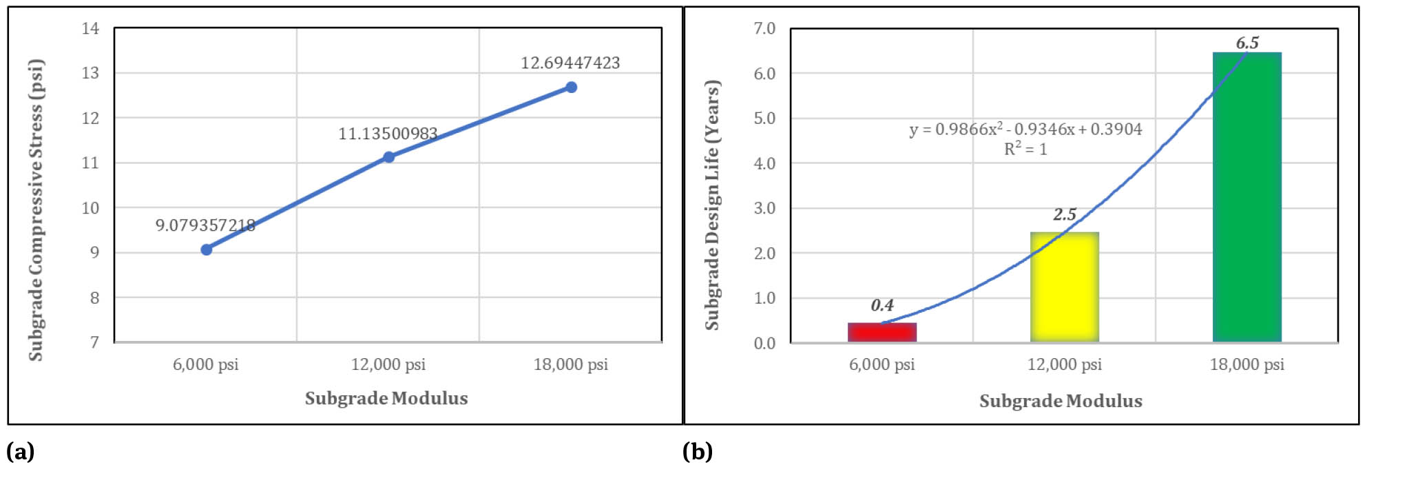
Subgrade with higher modulus offers a stiffer foundation since it has greater bearing capacity. Subgrade modulus is a very fundamental parameter and a principal input for rail track design in the KENTRACK program that influences the load carrying capability and the quality of the rail track structure. Figure 24 and Figure 25 shows the effect of three different subgrade modulus on subgrade compressive stress and subgrade design life for the two types of rail track.
Influence of subgrade modulus on subgrade compressive stress (a) and on subgrade service life (b) in granular rail track.

Influence of subgrade modulus on subgrade compressive stress (a) and on subgrade service life (b) in asphaltic overlayment track.
It can be noted that the subgrade compressive stress improves as the subgrade modulus enhances. Interestingly, the subgrade predicted service life is also increased significantly. For example, rising the subgrade modulus from 6,000 psi to 12,000 psi (100% higher) will improve the predicted subgrade design life in the granular and asphaltic overlayment rail track by a factor of 4.5 and 5.2, respectively. In addition, rising the modulus of subgrade from 12,000 psi to 18,000 psi (50% higher) will improve the predicted subgrade design life in the granular and asphaltic overlayment rail track by a lower factor of 1.6 and 2.1, respectively. These are due to the increase in modulus of subgrade that leads to a higher bearing capacity. According to Liu [6], the increment of the subgrade bearing capacity is always greater than the increment of the subgrade compressive stress. Therefore, even if the pressure on the top of subgrade increases, it should still perform well for an extended period.
Figure 26 presents the influence of subgrade modulus variation on asphalt tensile strain and asphalt design life in the asphalt overlayment rail track. The tensile strain reduces since the modulus of subgrade enhances. For the low subgrade moduli, in this case 6,000 psi, the subgrade unable to support the asphalt layer adequately. We can prove this conclusion by looking at the asphalt design life which is only 3.9 years. In other words, with the same load acting on the asphalt layer, the deformation of the asphalt is increased on the soft subgrade, resulting higher tensile strains on the bottom of the asphalt layer due to extreme bending strains. Furthermore, by using polynomial equation (R2 = 1) as can be seen in Figures 24, 25, and 26, we can predict the targeted subgrade and asphalt design life after determining the magnitude of subgrade modulus.

Influence of subgrade modulus on asphalt tensile strain (a) and on asphalt service life (b) in asphaltic overlayment rail track.
3.7 Effect of subgrade modulus and ballast-sub-ballast thickness in granular rail track
Figures 27 and 28 show the influence of subgrade modulus and ballast-sub-ballast thickness variations on subgrade compressive stress and subgrade design life in granular rail track, respectively. It can be expected that every single inch of ballast-sub-ballast thickness increment built on top of a subgrade layer with a high modulus will enhance sub-grade design life significantly. It is also interesting to notice that the subgrade design life of the granular rail track with a medium ballast-sub-ballast thickness (14 in) combined with a high subgrade modulus (18,000 psi) is identical to the subgrade design life of the granular rail track with a high ballast-sub-ballast thickness (21 in) combined with a medium subgrade modulus (12,000 psi).

Influence of subgrade modulus and ballast-sub-ballast thickness on subgrade compressive stress in granular rail track.

Influence of subgrade modulus and ballast-sub-ballast thickness on subgrade service life in the granular rail track.
Moreover, granular rail track that consists of ballast-sub-ballast thickness of 21 inches combined with a sub-grade with modulus of 18,000 psi provides the longest sub-grade design life, 19 years. In addition, it can be concluded that the subgrade compressive stress is more sensitive to the change in subgrade modulus than the change in ballast-sub-ballast layer thickness.
3.8 Effect of subgrade modulus and asphalt thickness in asphaltic overlayment rail track
Figure 29 and Figure 30 show the influence of subgrade modulus and asphalt thickness variations on subgrade compressive stress and subgrade design life in asphaltic overlayment rail track, respectively. It can be concluded that the subgrade compressive stress is more sensitive to the change in subgrade modulus than the change in asphalt layer thickness.

Influence of subgrade modulus and asphalt thickness on subgrade compressive stress in asphaltic overlayment rail track.

Influence of subgrade modulus and asphalt thickness on subgrade service life in asphaltic overlayment track.
Figures 31 and 32 show the influence of subgrade modulus and asphalt thickness variations on asphalt tensile strain and asphalt design life in asphaltic overlayment rail track, respectively. It can be inferred that the asphalt tensile strain is more sensitive to the change in asphalt layer thickness than the change in subgrade modulus.

Influence of subgrade modulus and asphalt thickness on asphalt tensile strain in asphaltic overlayment rail track.

Influence of subgrade modulus and asphalt thickness on asphalt service life in asphaltic overlayment track.
In addition, the asphalt service life in the asphalt overlayment rail track with an asphalt thickness of 13.78 in and subgrade modulus of 6,000 psi (7.4 years) is close to that in the asphalt overlayment rail track with an asphalt thickness of 10.63 in and subgrade modulus of 12,000 psi (7.5 years).
3.9 Effect of binder type and subgrade modulus in asphaltic overlayment rail track
Figures 33 and 34 show the influence of subgrade modulus and binder type variations on subgrade compressive stress and design life in asphaltic overlayment rail track, respectively. It can be concluded that the subgrade compressive stress is more sensitive to the change in subgrade modulus than the change in binder type used in this study.

Influence of subgrade modulus and binder type on subgrade compressive stress in asphaltic overlayment rail track.
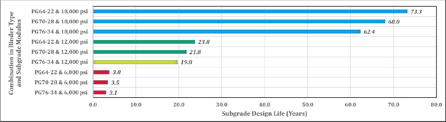
Influence of subgrade modulus and binder type on subgrade service life in asphaltic overlayment track.
Figures 35 and 36 show the influence of subgrade modulus and asphalt binder type variations on asphalt tensile strain and asphalt design life in asphaltic overlayment rail track, respectively. It is interesting to note that asphalt tensile strain is more sensitive to the change in subgrade modulus than the change in binder type used in this research.

Influence of subgrade modulus and binder type on asphalt tensile strain in asphaltic overlayment rail track.

Influence of subgrade modulus and binder type on asphalt service life in asphaltic overlayment track.
In addition, it is obvious that subgrade compressive stress and asphalt tensile strain were more sensitive to the change in asphalt layer thickness than the change in binder type.
4 Conclusions
On the basis of the results obtained in this study, the following conclusions can be drawn. Firstly, asphaltic overlayment rail track structure has a much longer predicted service life than granular rail track structure in overall parameter changes and variations. Therefore, it is suggested to apply the asphaltic overlayment rail track rather than the granular rail track especially for high load repetitions (> 500,000 per year) and high axle loads (> 36 tons). The suggested asphaltic overlayment rail track should consist of asphalt layer thickness of > 13.78 in (35 cm) and subgrade modulus of > 12,000 psi. In case the granular rail track is the only option, then it is suggested that the granular rail track should consist of minimum ballast-sub-ballast layer thickness of 21 in (53 cm) and minimum subgrade modulus of 18,000 psi to serve high load repetitions (> 500,000 per year) and high axle loads (> 36 tons).
Multiple sensitivity analysis revealed that:
The subgrade compressive stress is more sensitive to the change in subgrade modulus than the change in ballast-sub-ballast-asphalt layer thickness and the change in binder type, respectively.
The asphalt tensile strain is more sensitive to the change in asphalt layer thickness than the change in subgrade modulus and the change in binder type, respectively.
The subgrade compressive stress and asphalt tensile strain in the asphaltic overlayment track are more sensitive to the change in asphalt layer thickness than the change in binder type.
Further research might explore the effects of changing the upper binder grade (PG 76-22, PG 70-22, PG 64-22) and the lower binder grade (PG 64-22, PG 64-28, PG 64-34) on the subgrade compressive stress and asphalt tensile strain in the asphaltic overlayment rail track. In addition, KEN-TRACK originally considers the asphaltic underlayment rail track type where the asphalt layer is submerged and insulated by the thickness of the sleeper and ballast. Therefore, the future research on the application of asphaltic overlayment rail track should consider the higher asphalt temperature through seasons since the asphalt layer is exposed to larger temperature extremes from winter to summer.
The economic feasibility is an important aspect that is directly linked to the popular applications of asphalt trackbeds but has not been studied in detail in this or another research. There are many factors that affect the economic feasibility, such as geographical and climatic situations, prices for material and labor, and subgrade conditions. The construction of asphalt trackbed may cost more as compared to the granular rail track. However, the difference varies locally and the overall costs considering maintenance over the life of the track may be substantially less. For those areas where good quality ballast is rare and expensive, the difference in cost will be small because lower quality aggregates can be used in asphalt mix. The reduction of maintenance is necessary for verifying this benefit. Proving the effectiveness of asphaltic overlayment rail track depends not only on the structural advantage but also on the economic feasibility. It would be interesting to conduct a detailed study of this aspect.
Funding information: The authors state no funding involved.
Author contributions: All authors have accepted responsibility for the entire content of this manuscript and approved its submission.
Conflict of interest: The authors state no conflict of interest.
References
[1] Setiawan DM. Utilization of 60/70 penetration grade asphalt on ballast structures with the variation of percentage and the number of pouring layers. J Mech Behavior Mater. 2019;28(1):107–118.10.1515/jmbm-2019-0013Search in Google Scholar
[2] Zakeri JA, Mosayebi SA. Study of ballast layer stiffness in railway tracks. Gradevinar. 2016;68(4):311–318.Search in Google Scholar
[3] Setiawan DM, Rosyidi SAP. Track quality index as track quality assessment indicator. Proceeding of the 19th International Symposium of Indonesian Inter-University Transportation Studies Forum (FSTPT), Universitas Islam Indonesia, Yogyakarta, Indonesia, 2016, Ch. 2: 197–207.Search in Google Scholar
[4] Setiawan DM. Pembatasan Kecepatan maksimum dan kaitannya terhadap kapasitas lintas jalur kereta api Muara Enim–Lahat Sumatera Selatan. Prosiding Seminar Nasional Teknik Sipil ke-VI 2016, Surakarta, Indonesia, 2016, 36–46.Search in Google Scholar
[5] Duong TV, Cui YJ, Tang AM, Dupla JC, Canoua J, Calon N, Robinet A. Investigating the mud pumping and interlayer creation phenomena in railway sub-structure. Eng Geology. 2013;171:45–58.10.1016/j.enggeo.2013.12.016Search in Google Scholar
[6] Liu S. KENTRACK 4.0: A railway trackbed structural design program. Theses and Dissertations, Department of Civil Engineering, University of Kentucky, USA, 2013.Search in Google Scholar
[7] Robnett QL, Thompson MR, Knutson RM, Tayabji SD. Development of a structural model and materials valuation procedures. Rep. DOT-FR-30038, Ballast and Foundation Materials Research Program, University of Illinois, USA, 1975.Search in Google Scholar
[8] Rose JG, Shushu L, Souleyrette, R. KENTRACK 4.0: A railway trackbed structural design program. Proceedings of the 2014 Joint Rail Conference.10.1115/JRC2014-3752Search in Google Scholar
[9] Fateen S. A finite element analysis of full depth asphalt railway track. Master’s Thesis, Department of Civil Engineering, University of Maryland, USA, 1972.Search in Google Scholar
[10] Chang CS, Adegoke CW, Selig ET. GEOTRACK model for railroad track performance. J Geotech Eng Div ASCE. 1980;106(11):1201–1218.10.1061/AJGEB6.0001059Search in Google Scholar
[11] Rose JG, Agarwal N, Brown JD, Ilavala N. KENTRACK, a performance-based layered elastic railway trackbed structural design and analysis procedure: A tutorial. Proceedings of the 2010 Joint Rail Conference.10.1115/JRC2010-36067Search in Google Scholar
[12] Huang YH, Lin C, Deng XJ, Rose J. KENTRACK, A computer program for hot-mix asphalt and conventional ballast railway trackbeds. Asphalt Institute Publication RR-84-1 and National Asphalt Pavement Association Publication QIP-105, USA, 1984.Search in Google Scholar
[13] Lee SH, Vo HV, Park DW. Investigation of asphalt track behavior under cyclic loading: full-scale testing and numerical simulation. J Test Eval. 2018;46(3):934–942.10.1520/JTE20160554Search in Google Scholar
[14] Setiawan DM. The role of temperature differential and subgrade quality on stress, curling, and deflection behavior of rigid pavement. J Mech Behavior Mater. 2020;29(1):94–105.10.1515/jmbm-2020-0010Search in Google Scholar
[15] Setiawan DM, Rosyidi SAP. Vertical deformation and ballast abrasion characteristics of asphalt-scrap rubber track bed. Inter J Adv Science Eng Inform Tech. 2018;8(6):2479–2484.10.18517/ijaseit.8.6.7411Search in Google Scholar
[16] Setiawan DM, Rosyidi SAP, Budiyantoro C. The role of scrap rubber, asphalt and manual compaction against the quality of ballast layer. Jordan J Civ Eng. 2019;13(4):594–608.Search in Google Scholar
[17] Setiawan DM. Application of 60/70 grade bitumen with layer variations on ballast structures. Inter J Adv Science Eng Inform Tech. 2021;11(2):698–704.10.18517/ijaseit.11.2.9898Search in Google Scholar
[18] Lee SH, Choi YT, Lee HM, Park DW. Performance evaluation of directly fastened asphalt track using a full-scale test. Constr Build Mater. 2016;113: 404–414.10.1016/j.conbuildmat.2016.02.221Search in Google Scholar
[19] ASTM D 2493-01. Standard Test Method for Indirect Tension Test for Resilient Modulus of Bituminous Mixture, American Society for Testing and Materials, 2009.Search in Google Scholar
[20] Garcia G, Thompson M. HMA dynamic modulus predictive models (a review). Techni. Rep. IHR-R39 Project, Department of Civil and Environmental Engineering, University of Illinois at Urbana-Champaign, USA, 2007.Search in Google Scholar
[21] Advanced Research Associates. 2002 design guide: design of new and rehabilitated pavement structures. NCHRP 1-37A Project, National Cooperative Highway Research Program, National Research Council, Washington, D. C., USA, 2004.Search in Google Scholar
[22] Witczak MW, Kaloush K, Pellinen T, El-Basyouny M, Von Quintus H. Simple performance test for superpave mix design. NCHRP Rep. 465, Transportation Research Board, Washington, D. C., USA, 2002.Search in Google Scholar
[23] Asphalt Institute. HMA Trackbeds – Hot mix asphalt for quality railroad and transit trackbeds. Information Series 137, 1998, USA.Search in Google Scholar
© 2021 Dian M. Setiawan, published by De Gruyter
This work is licensed under the Creative Commons Attribution 4.0 International License.
Articles in the same Issue
- Research Articles
- The elastic-plastic properties of an anti-icing coating on an aluminum alloy: Experimental and numerical approach
- Optimization of recycled slag-fresh flux mixture based upon weld bead quality for submerged arc welding of stainless steel
- Design and optimization of differential capacitive micro accelerometer for vibration measurement
- Mechanical performance of abrasive sandpaper made with palm kernel shells and coconut shells
- Experimental investigation of WEDM process through integrated desirability and machine learning technique on implant material
- Mechanical properties and microstructural characteristics of rotating arc-gas metal arc welded carbon steel joints
- Assessment of cement replacement with fine recycled rubber particles in sustainable cementitious composites
- Structural response and sensitivity analysis of granular and asphaltic overlayment track considering linear viscoelastic behavior of asphalt
- Unmanned aerial vehicle evasion manoeuvres from enemy aircraft attack
- Effect of corrosion on surface degradation of galvanized steel in poultry dung, pig dung and urea solutions using rice straw as an inhibitor
- Mathematical modeling of AZ30 magnesium alloys at high temperature using the ring compression test and genetic algorithm method
- Study on hot deformation behavior and workability of stir-cast Al6063-6wt.% steelp based composites
- The effects of processing parameters on the formation of oxide layers in aluminium alloys using plasma electrolytic oxidation technique
- Behavior of green reactive powder mortar reinforced with steel fibers
- On the hygrothermal properties of sandcrete blocks produced with sawdust as partial replacement of sand
- Mechanical behavior of thin-walled steel under hard contact with rigid seabed rock: Theoretical contact approach and nonlinear FE calculation
- Mechanical properties and microstructural characteristics of rotary friction welded dissimilar joints of rolled homogeneous armor steel and medium carbon steel
- Studies of carboxylated nitrile butadiene rubber/butyl reclaimed rubber (XNBR/BRR) blends for shoe soles application
- Mechanical properties of wire arc additive manufactured carbon steel cylindrical component made by gas metal arc welding process
- Synthesis and mechanical characterization of Si3N4 reinforced copper-tin matrix composites
- Analysis of plated-hull structure strength against hydrostatic and hydrodynamic loads: A case study of 600 TEU container ships
- Mechanical performance investigation of lignocellulosic coconut and pomegranate / LDPE biocomposite green materials
- Special Issue MICAP-2021
- Double hydrothermal synthesis of iron oxide/silver oxide nanocomposites with antibacterial activity**
- Enhanced photocatalytic activity of TiO2-CdS composite nanofibers under sunlight irradiation**
- Structural properties of CoxCu1−xFe2O4 solid solution**
- Green-synthesis of Ag2O nanoparticles for antimicrobial assays**
- Effect of current density on the porous silicon preparation as gas sensors**
- A mechanochemical preparation, properties and kinetic study of kaolin–N, P fertilizers for agricultural applications**
- Impact strength of surface treated SS316L wires reinforced PMMA**
- Computational studies on electronic and optical properties of dopamine derivatives structure: A DFT study**
- Multilayer coating effects on the thermal conductivity of tools using an electric furnace technique**
- The positron and mechanical parameters of a cold-worked aluminum alloy (3004) Using PALT, PADBT and HV**
- Effect of thermal annealing on the structural and optical properties of TiO2 nanostructures**
- Improvement of forging die life by failure mechanism analysis**