Distributed Multi-agent Bidding-Based Approach for the Collaborative Mapping of Unknown Indoor Environments by a Homogeneous Mobile Robot Team
-
Abdelfetah Hentout

 ,
Abderraouf Maoudj
,
Abderraouf Maoudj

Abstract
This paper deals with the problem of the collaborative mapping of unknown indoor environments by a homogeneous mobile robot team. For this aim, a distributed multi-agent coordination approach is proposed for the mapping process to offer a global view of the entire environment. First, the scheme starts by assigning the most suitable robots to the different zones of the environment to be mapped based on a bidding strategy. Then, while a Robot agent of the group explores its local surroundings and collects information about its neighborhood, it sends mapping data to the Human/Machine Interface agent to integrate them into a single global map. Furthermore, a geometric map representation and an algorithm based on obstacles and environment limits detection are used to provide an explicitly geometric representation of the workspace. For validation purposes, Player/Stage simulator is used to show the effectiveness of the proposed distributed approach and algorithms without needing a real multi-robot system and environment. Finally, various scenarios have been carried out and results are compared in terms of (i) required mapping time, (ii) accuracy of the global generated map, and (iii) number of exchanged messages between the agents.
1 Introduction
The exploration and mapping of unknown environments are fundamental research problems in mobile robotics. They consist, in most difficult cases, of discovering unknown or changed environments to build an accurate representation. The exploration can be defined as an iterative process determining a new goal for the robot and its navigation toward the goal. The process is terminated whensoever a complete map of the unknown environment is created [9]. The resulting maps are often used by the robots to perform complex tasks. They are also essential for humans to recognize remote, inaccessible, or hostile environments. Researches in this area were initially concentrated on single robot systems; thereafter, the miniaturization of robotic devices and costs decreasing enabled to deploy multi-robot systems (i.e. mobile robot team) [5, 19].
The global goal of multi-robot exploration is to build a map of unknown environments by exploiting several robots equipped with sensors. The obvious underlying assumption is that the explored area is larger than the sensing range of each robot. All the numerous methods proposed in the literature are based on some sort of incremental integration: a newly acquired partial map is integrated with the old maps [2]. Most approaches proceed as follows [23]. First, a set of potential target zones is determined. Such targets are often located close to unknown areas to allow the robots to observe the unknown spaces. Then, each target location is assigned to a robot. Finally, the robots move toward those target zones and include their observations obtained along the paths into a global map. This process is repeated until the whole workspace has completely been explored. However, the utilization of such systems to collaboratively map environments remains until now a difficult problem [9]. To create a coherent model for any environment, a full exploration should be done. In addition, data should be integrated into one global map. This involves solving three main subproblems: (i) deployment strategy, (ii) coordination architecture, and (iii) collaborative mapping.
Deployment strategy answers the following question: Given what the team know about the world, where should it move to gain as much new information as possible? [25]. For a good mapping minimizing imposed constraints (time, energy, etc.), it is important to keep the robots well deployed and distributed to cover the whole workspace. The different areas to be explored may be assigned in various ways to robots. Thus, several deployment methods have been proposed such as the frontier-based approach [6, 25], Hungarian method [7, 9], and trade-based approach [26].
Coordination architecture deals with the definition and organization of interrelations between the robots and the decision system (control unit). It is thus possible to distinguish two classes [8]. (i) In centralized architectures, a single robot (central unit) acts as the coordinator that monitors the movement of the robots; hence, the goal accomplishment is centered on this coordinator. In addition, this robot is responsible for the global information on environment and robots [18]. In this type, the control unit has a global view of the world where the robots evolve; this allows the control unit to optimally take decisions. However, its disadvantage is that it is effective for a small number of robots, and if the central control unit fails, the whole system fails too [27]. (ii) In distributed architectures, there is no single coordinator in the environment; the whole system control and decision-making are distributed on the architecture units, and tasks execution is distributed on the system components. Furthermore, each robot coordinates its own movement and ensures that it does not collide with any other robot during goal accomplishment [8]. This type allows to easily expand the robots number and it is demonstrated that these architectures are fault-tolerant and robust to robot failures [21].
Collaborative mapping is the phase of building a map that reflects the environment structure by accurately integrating all data collected by the robots during exploration. Building a map requires choosing the representation nature among the three following models. (i) The metric model is a detailed geometric representation of the world. Its main advantages is that it is easily interpreted by humans and provides well-defined relationship with real world; its weakness is that it requires more storage capacities and it is sensitive to measurement errors [11]. (ii) The topological model represents the environment as a graph; the nodes correspond to regions and arrows connecting these nodes mark the possibility to directly move from one region to another. This model can provide a compact representation of the environment while still retaining all key locations and connectivity between these locations, which makes it easy to understand by humans [15]. However, its main shortcoming is that recognizing environment places can be difficult [4]. (iii) The hybrid model is the hybridization between metric and topological models (i.e. topological maps containing metric information). These maps simultaneously benefit from the advantages of using these representation types but also suffer from both limits [28]. Moreover, few works apply these two models at the same time. As both metric and topological maps are complementary representations, there seems to be a recent tendency to merge these representations for an improved robot localization and navigation [20].
This paper proposes and implements a distributed multi-agent bidding-based approach to allocate zones to robots for environment mapping. The team evolves inside indoor environments with known original structure but whose actual structure has been modified [20]. For this purpose, we opted for the following: (i) a distributed multi-agent coordination architecture, (ii) an autonomous bidding-based deployment approach that seeks to assign robots to the different areas of the world, and (iii) a metric model to explicitly represent the environment geometry. An agent (human/machine interface agent or HMIA) offers a zone and the other agents (robot agents or RAs) interact with each other by exchanging their bids. Thereafter, the agent bidding with the best price than all the others will hold (explore and map) the zone.
In addition to the analysis of the related research works on the exploration and mapping of unknown environments, the principal contributions of this paper are summarized as follows. First, our approach works in unknown indoor environments with a high number of mobile robots. Second, it is generic in the sense that we just need to associate the required number of RAs to adapt the proposed approach to another team of mobile robots. Third, the RAs are autonomous and independent and use local information by exploring a distributed approach through no master/slave relationship between these agents. Fourth, this approach combines three parameters (necessary time to move toward the target, number of allocated zones, and accuracy of the robot sensor) that allow obtaining a good balance between final mapping times and the quality of obtained maps. Finally, the accuracy of the generated global map is very acceptable while only needing short calculation time for robots assignment, environment exploring, and mapping.
The rest of the paper is organized into five sections. Section 2 states the problem. Section 3 describes the proposed distributed multi-agent control architecture, resolution approach, and interactions between the control system agents. Section 4 presents our own-established validation scenarios and discusses the main obtained simulation results. Section 5 concludes the paper and presents some future works.
2 Problem Statement
The problem to be solved by the proposed approach is how to choose the appropriate target zones for the individual robots so that they simultaneously explore different regions of an unknown environment while minimizing the imposed constraints (time, energy, etc.). Each robot is equipped with proximity sensors with limited range and field of vision, localization capability, and limited-range communication capacity. The indoor environments considered in this work are generally structured; they consist of one-level space having a main corridor, many disjoint rooms, and stairs. These characteristics guarantee, on the one hand, a unique and sequential access to environment. On the other hand, the well-defined regions of the environment can be explored simultaneously [20].
2.1 Formulation of the Problem
The problem of multi-robot exploration is a kind of multi-robot task allocation [10], where tasks are new best goal locations toward which the mobile robots have to navigate [9]. The problem is to find the best assignment of n goal zones to m identical robots that minimizes the predefined constraints [2] while exploring and building a map M of the unknown indoor environment. Therefore, this problem has been formulated as an optimization problem [16] of best assignment of n tasks on m machines studied in operational research [9]: tasks are assimilated to zones and machines to robots (i.e. n zones and m robots). The goals are assigned to robots using the exploration strategy that can be formalized as follows.
Let us consider a set of m homogeneous mobile robots R={r1, …, rm} at their current positions C={c1, …, cm}, mapping an environment of dimension L×W (length and width) composed of a set of n zones Z={z1, …, zn} located at positions G={g1, …, gn}. The problem is to determine a goal gj∈G for each robot ri∈R that minimizes the imposed constraints while exploring and mapping the whole environment. We assume that
M represents the global map generated by all the active robots of the system.
ci(xi, yi, θi) is the current position coordinates and orientation angle of the robot ri in the global frame RA.
Aij is a binary variable assigning robot ri (i=1, …, m) to zone zj (j=1, …, n). Aij=1 means that ri is assigned to map zj; otherwise, Aij=0.
Pij corresponds to the mapping time of zone zj by robot ri. It is calculated using the Euclidean distance (based on the robot velocity) between ci (the current position of robot ri) and gj (the coordinates of zone zj.
tj corresponds to the mapping start time of zone zj.
TMax is the objective function to be optimized for the overall mapping process (all the zones).
The mathematical formulation of the considered problem is illustrated as follows:
subject to
Equation (1) is the objective function; it must be minimized. Constraint (2) calculates the objective function value. Constraint (3) assures that a specific zone zj∈Z is mapped by one robot ri∈R only. Constraints (4) and (5) define the decision variables.
Various objective functions have been proposed in the literature such as distance traveled, time taken, or energy expended; some of them basically combine both information gain/loss or expected benefits [24] with the required traveling distance to the goal [3, 9]. In this paper, each robot ri∈R calculates a combination of three parameters: (i) the necessary time to move toward the goal zone zj (function of the distance traveled by the robot to reach the target zone and its velocity), (ii) the number of its allocated zones, and (iii) the accuracy of its proximity sensor. In our assignment approach, for each exploration target in the environment (i.e. zone), we define a Costij to evaluate the robot ri cost for mapping such a zone zj. This cost function is used to guide the decision-making process of all the agents and to select the best robot with minimum cost for each zone.
Let us consider Ei as the accuracy of the proximity sensor equipping the robot ri∈R: Ei=1, meaning that data delivered by the sensor are very precise (i.e. accuracy=100%); Ei=0 means that these data are very inaccurate.
The cost of robot ri∈R (i=1, …, m) to map zone zj∈Z (j=1, …, n) is Costij; it is calculated by Equation (6) as follows:
where α, β, and γ are constant weights; α+β+γ=1.
2.2 Detection of Obstacles and Environment Limits
The proposed algorithm is based on the detection of obstacles and environment limits. We point out that each mobile robot is equipped with one proximity sensor (e.g. laser range finder) as shown in Figure 1:

Obstacles and Environment Limits Detection and Calculation of their (xk, yk) Position Coordinates using the Proximity Sensor of Robot ri.
ri corresponds to the robot that has detected the current point (obstacle or environment limit).
robotTeam represents the list of all the active mobile robots of the team.
proximitySensori is the proximity sensor equipping the robot ri.
rangei is the maximum detection range of the proximity sensor of robot ri.
fovi corresponds to the field of vision of the proximity sensor of robot ri.
Ni is the maximum number of data provided by the proximity sensor of robot ri.
radiusi contains the measurements delivered by the proximity sensor of ri.
φik is the offset of the kth proximity sensor data from the orientation angle of robot ri.
(xk, yk) represent the actual position of the kth detected obstacle/environment limit in the global frame RA. They can be obtained by Equations (7) and (8):
(7)(8)listDatai represents the coordinates list of obstacles or environment limits detected by robot ri.
3 Proposed Multi-agent Resolution Approach
Distinct agents are solicited to ensure a modular and robust control scheme. The interactions among these entities provide the robots with required behaviors to accomplish tasks [12]. The proposed control system distributes the computational process among its agents. Each only completes a part of the computational tasks with lack of a full global view. For solving the problem, all agents interact and collaborate to satisfy the global objective.
3.1 Distributed Multi-agent Control Architecture
The multi-agent architecture for mobile robot team control is based on that previously proposed in Ref. [17]. As shown in Figure 2, it distinguishes two kinds of agents:

Overview of the Proposed Distributed Multi-agent Architecture for Mobile Robot Team Control.
Human/Machine Interface Agent (HMIA): HMIA is not involved in the decision-making process; it only consists of an interface between the control system and the robot team. HMIA communicates with Robot Agents by sending requests and receiving data on tasks/operations execution (mapping information, etc.).
Robot Agents (RAs): An RA controls the physical robot, makes decisions, and carries out operations. These agents also assign the most suitable robot to map a given zone through coordination and negotiation. RAs communicate with HMIA by sending data/reports and receiving requests.
3.2 Proposed Strategy for Zone Allocation
Among the important advantages of multi-agent approaches is to allow one agent to locally solve subproblems and to propose a global solution as a result of interactions between the different agents [14]. Consequently, the proposed multi-agent approach distributes the mapping tasks of unknown environments on the RAs; all these agents interact and collaborate to satisfy the global objective.
The proposed and implemented mapping algorithm is split up into two parallel running parts. The first is carried out by HMIA; the second part is executed by RAs.
3.2.1 Human/Machine Interface Agent (HMIA)
Figure 3 describes the overall behavior of HMIA. The task starts by receiving a request (REQUEST message) from the operator to map an unknown indoor environment. In addition, the deployment approach, number of active mobile robots (m), number of zones constituting the environment (n) and their parameters are sent within an INFORM message. Then, HMIA creates the required number of RAs, sends them an INITIALIZE message (with their respective initial positions), and waits for their responses. When HMIA receives INITIALIZED messages from all the active RAs, two cases could be distinguished depending on the deployment approach the operator adopted at the beginning:
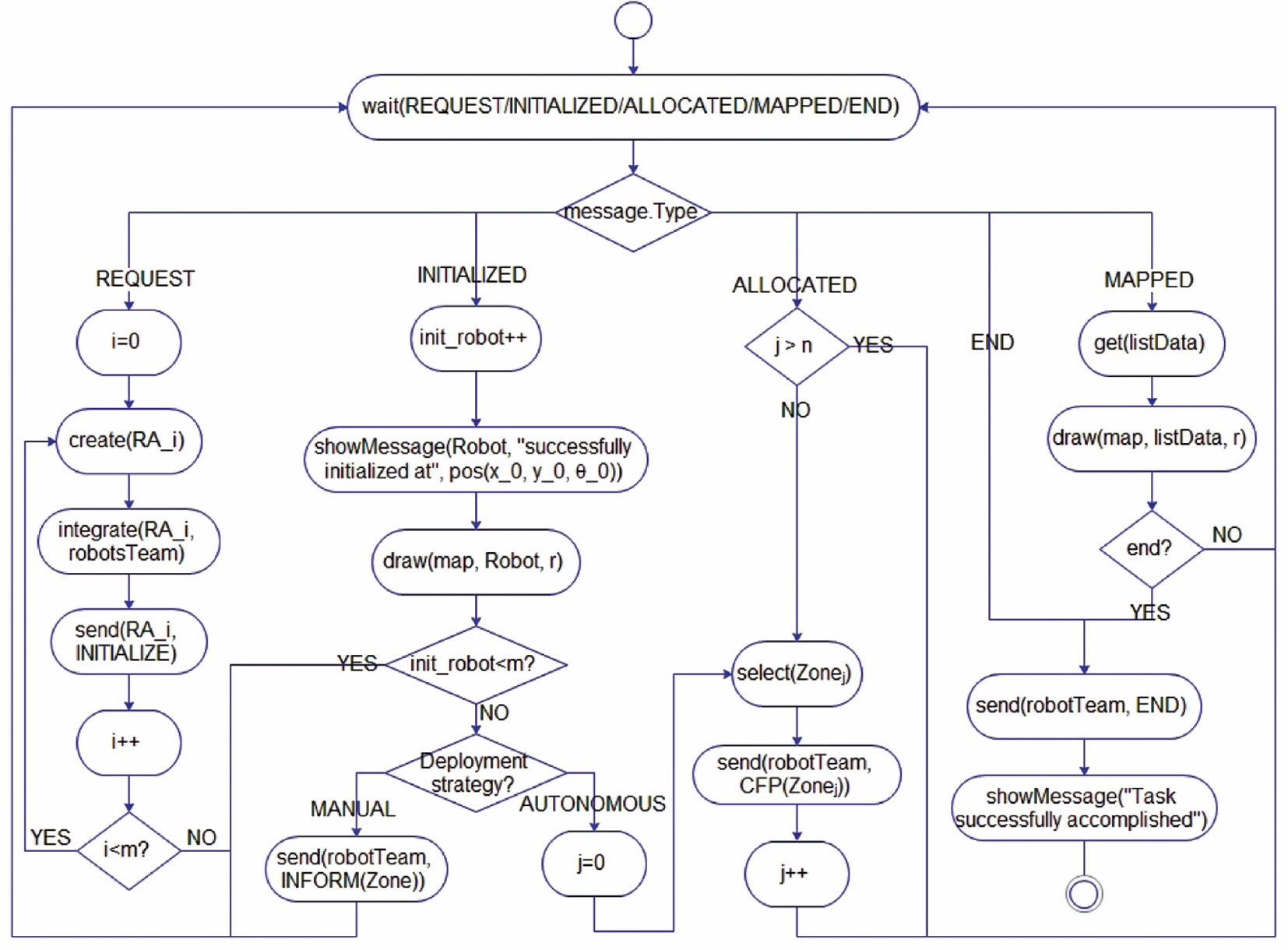
Behavior Diagram of the Human/Machine Interface Agent (HMIA).
create(Agent) creates an Agent to locally control a robot. integrate(Agent, Team) integrates a new Agent into Team. send(Agent, Message) sends Message to Agent. get(Data) receives Data from the operator, another agent, a proximity sensor, or from the knowledge database. select(Zone) selects Zone to be allocated. draw(map, listData/Robot, r) draws listData/Robot onto map with color r. showMessage(Message) displays Message on the screen of the operator.
Random deployment: HMIA replies by sending the deployment positions gj∈G (j=1, …, n) of the robots within an INFORM message.
Autonomous deployment: HMIA replies by sending a CFP message for each zone zj∈Z (j=1, …, n) one by one while respecting their rank, that is, starting by z1, then z2, …, until arriving to zn. RAs will proceed in parallel to assign each zone to the most appropriate robot as detailed in the next subsection.
In both cases, HMIA sends MAP message to all RAs. Then, each time that HMIA receives MAPPED message with the current coordinates of an obstacle or environment limit, this agent adds these data to the global map (with the corresponding color of the specified robot). This procedure continues until mapping the entire world or the operator decides to terminate the process.
3.2.2 Robot Agents (RAs)
Figure 4 explains the global behavior of RA. After receiving INITIALIZE message from HMIA, each RA will create its proximity sensor and initialize its parameters [ci(xi, yi, θi), fovi, rangei, …](i=1, …, m). Once done, RA sends INITIALIZED message to HMIA to inform it about the success of these actions. Subsequently, HMIA distinguishes two possibilities:

Behavior Diagram of Robot Agent.
initialize(field1, …, fieldn) initializes field1, …, fieldn. create(sensor) creates a proximity sensor to equip the robot. evaluate(Zone) evaluates the local cost of RA relative to Zone; it is sent to the other RAs. best(cost1, …, costi− 1, localCost, costi+1, …, costm) selects minimum value between RA propositions. moveRobot(Zone) moves the robot to Zone while avoiding obstacles. localizeRobot() returns the current position ci(xi, yi, θi) of the robot ri inside its workspace. add(v1, …, vn, listData) adds v1, …, vn to listData.
Random deployment: Each RA gets its target position gj∈G, which has been introduced by the human operator within the INFORM message.
Autonomous deployment: In this case, the robots’ deployment positions are the result of interactions between all RAs. The zone allocation process is done as follows. When a robot ri∈R receives a zone zj∈Z to be allocated from HMIA within the CFP message, this RA calculates its local cost Costij [as shown by Equation (6)]; then, it broadcasts this cost to the other RAs. After receiving all the costs from the other RAs, this RA compares them to its local cost. The agent holding the best proposition will be assigned to map this zone. If two agents or more proposed the same cost, the agent having the smallest rank inside the team will be assigned to map that zone. Next, this agent will inform HMIA by sending ALLOCATED message.
In both cases, HMIA continues by sending MAP message to all the active RAs of the control system. Thereafter, each RA moves toward its calculated/imposed deployment position. During the motion, RA calculates the current position of the detected obstacle/environment limit [as shown by Equations (7) and (8)] and sends data (MAPPED message) to HMIA to build the global map. This procedure continues until receiving END message from HMIA.
3.3 Interaction Between the Agents of the Control System
A key component to a multi-agent system is the mechanism that allows agents to interact [1]. This interaction is implemented through messages exchange protocol. Figure 5 gives an overview of the whole interactions between HMIA, RAs, and the human operator:

Sequence Diagram for the Whole System.
REQUEST: This message is sent by the operator to HMIA to execute a task (i.e. indoor environment mapping).
INFORM: This message allows exchanging useful information between the agents of the control system.
INITIALIZE: HMIA sends this message to all RAs to create the required mapping sensors and initialize their different parameters.
INITIALIZED: After receiving the previous message and initializing its parameters, each RA replies by sending INITIALIZED message to HMIA.
CFP: In case of autonomous deployment strategy, HMIA broadcasts the different zones of the environment on the active RAs through a CFP message.
PROPOSE: Just after receiving CFP message, each RA sends its local proposition on the current zone to the other RAs within a PROPOSE message.
ALLOCATED: Once the allocation of a zone is achieved, the corresponding RA informs HMIA by sending ALLOCATED message.
MAP: Once all the RAs sent INITIALIZED messages (random deployment) or when all the zones have been allocated to robots (autonomous deployment), HMIA begins the mapping process by sending MAP message to all the active RAs.
MAPPED: Following the mapping of a part of the surrounding environment of a robot, RA sends this message to HMIA within the calculated position of the detected obstacle/environment limit to be integrated into the global generated map.
END: HMIA sends this message to all the active RAs to stop the mapping process.
4 Simulation Results
For validation purposes, Player/Stage simulator has been used to implement the proposed distributed mapping approach. Player/Stage is a 2D simulator developed at the South California University [22] to allow simulating a robot population. It simulates a large number of equipment including cameras, lasers, grippers, etc. In this work, Player-3.0.2 and Stage-3.2.2 [https://sourceforge.net/projects/playerstage/] have been used.
Several validation scenarios for the random and autonomous deployment approaches have been performed. The main results are compared in terms of (i) required mapping time, (ii) global map accuracy, and (iii) number of messages exchanged between the agents. For the last comparison parameter, communication between the agents is assumed to be unlimited for the whole control system.
The mapping time tMapping is calculated by Equation (9); the accuracy of the global generated map is calculated by Equation (10), where:
tStart and tEnd represent the start time and end time of mapping, respectively.
ξ is the size of fictive obstacles/environment limits perceived by the robots.
σ is the size of real obstacles and environment limits detected by the team.
Positions are given in meters (m), time in seconds (s), and accuracy in percentage (%).
4.1 Validation Workspace
It is necessary to create a simulation workspace; thus, the ground floor of the DPR of CDTA is considered. As shown in Figure 6 [13], this environment of about L×W=32×22 m2 is large enough to show the performances of the proposed collaborative mapping approach using many robots. Also, the environment has seven workrooms with a long shared corridor (i.e. Z={z1, …, z8}). It should be noted that Z only contains zones that are reachable by at least one robot.
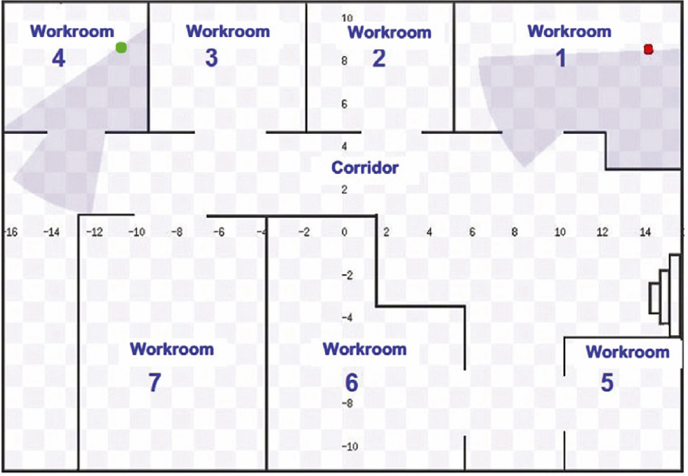
Ground Floor of the DPR of the CDTA Research Center.
The number of robots is an important aspect to consider when designing a team. If this number increases, the difficulty to coordinate them increases too. As stated in Ref. [20], the team for collaborative exploration consists of about 2–5 robots. Therefore, a robot team composed of several Pioneer 2DX mobile robots is considered to collaboratively map this workspace (i) R={r1, r2}, (ii) R={r1, …, r3}, (iii) R={r1, …, r4}, and (iv) R={r1, …, r5}. Each robot can localize itself based on data delivered by its odometry sensors.
Figure 7 describes the developed control interface for indoor environment mapping by a team. Each robot maps the area that it has explored; for example, green area was mapped by green robot, red area by red robot, etc.

Developed Interface for the Collaborative Mapping of Indoor Environments.
4.2 Validation Scenarios
To provide a better comparison support for the proposed distributed multi-agent approach, all the parameters of the utilized robots and the considered indoor environments have to be identical. Unfortunately, the absence of this information in the literature (environments, parameters, and initial conditions of the robots) has led us to establish our own validation scenarios.
Using Player/Stage, a series of simulations was performed with different numbers of robots. In addition, as the work is done in simulation, the accuracy of the proximity sensors is considered to be equal to 100%. Finally, each robot is equipped with a laser sensor having the following characteristics (Table 1):
Characteristics of the Proximity Sensor Equipping all the Robots.
| Range | FOV | Ei | Ni | α=β=γ |
|---|---|---|---|---|
| 8 m | 180° | 1 | 360 |
|
For each scenario, two different cases are considered (i) random deployment and (ii) autonomous deployment. For both cases, the current positions of the robots C={c1, …, c5} and the coordinates of the different zones G={g1, …, g8} are supposed to be as follows (Table 2).
Parameters of the Considered Validation Scenarios.
| Current positions of the robots | r1 | c1(6, −9) |
| r2 | c2(7, −9) | |
| r3 | c3(8, −9) | |
| r4 | c4(9, −9) | |
| r5 | c5(10, −9) | |
| Coordinates of the environment zones | z1 | g1(10.5, 8.1) |
| z2 | g2(2, 8.1) | |
| z3 | g3(−5, 8.1) | |
| z4 | g4(−12.5, 8.1) | |
| z5 | g5(13, −8.1) | |
| z6 | g6(0.5, −5.5) | |
| z7 | g7(−8.1, −5.5) | |
| z8 | g8(0, 2) |
4.2.1 First Scenario
The first scenario consists of using two mobile robots R={r1, r2} to map Z={z1, …, z8}. Table 3 gives the assigned zones to RAs for random and autonomous deployment approaches. Figure 8A and B illustrates the obtained global maps for both modes, respectively.
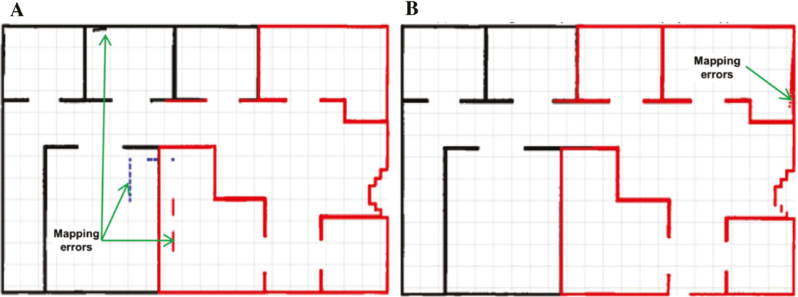
Generated Global Maps for the Scenario with Two Mobile Robots: (A) Generated Map for the Random Approach and (B) Generated Map for the Autonomous Approach.
Assigned Areas for the Scenario with Two Robots.
| Deployment approach | Robot | Assigned zones |
|---|---|---|
| Random | Robot 1 | Z2→Z8→Z1→Z6→Z5 |
| Robot 2 | Z7→Z3→Z4 | |
| Autonomous | Robot 1 | Z6→Z8→Z2→Z1 |
| Robot 2 | Z5→Z7→Z3→Z4 |
4.2.2 Second Scenario
This scenario considers three mobile robots R={r1, …, r3} to map Z={z1, …, z8}. Table 4 gives the obtained results for both modes.
Assigned Areas for the Scenario with Three Robots.
| Deployment approach | Robot | Assigned zones |
|---|---|---|
| Random | Robot 1 | Z2→Z8→Z1 |
| Robot 2 | Z7→Z3→Z4 | |
| Robot 3 | Z6→Z6 | |
| Autonomous | Robot 1 | Z6→Z8→Z2 |
| Robot 2 | Z7→Z3→Z4 | |
| Robot 3 | Z5→Z1 |
4.2.3 Third Scenario
In this scenario, a team composed of four mobile robots R={r1, …, r4} is considered to parallel map the whole environment Z={z1, …, z8}. Table 5 gives the zones assigned to the robots for both deployment modes. Figure 9A and B gives the obtained results for the first and second cases, respectively.

Generated Global Maps for the Scenario with Four Robots: (A) Generated Map for the Random Approach and (B) Generated Map for the Autonomous Approach.
Assigned Areas for the Scenario with Four Robots.
| Deployment approach | Robot | Assigned zones |
|---|---|---|
| Random | Robot 1 | Z1→Z2 |
| Robot 2 | Z4→Z8 | |
| Robot 3 | Z5→Z6 | |
| Robot 4 | Z7→Z3 | |
| Autonomous | Robot 1 | Z6→Z8 |
| Robot 2 | Z7→Z3 | |
| Robot 3 | Z1→Z2 | |
| Robot 4 | Z5→Z4 |
4.2.4 Fourth Scenario
In this last scenario, five robots R={r1, …, r5} are used for exploring and mapping the workspace Z={z1, …, z8}. Table 6 gives the zones assigned to the robots for both random and autonomous deployment modes.
Assigned Areas for the Scenario with Five Mobile Robots.
| Deployment approach | Robot | Assigned zones |
|---|---|---|
| Random | Robot 1 | Z1→Z2 |
| Robot 2 | Z8→Z5 | |
| Robot 3 | Z6 | |
| Robot 4 | Z3→Z7 | |
| Robot 5 | Z4 | |
| Autonomous | Robot 1 | Z6→Z8 |
| Robot 2 | Z7→Z4 | |
| Robot 3 | Z2→Z3 | |
| Robot 4 | Z1 | |
| Robot 5 | Z5 |
4.3 Discussion of Obtained Results
Different simulation scenarios have been carried out for the problem of the collaborative mapping of an unknown indoor environment (the ground floor of DPR of CDTA) by a homogeneous mobile robot team. The proposed distributed multi-agent coordination approach assigned the most suitable robot to explore and map a specific zone based on the implemented bidding strategy.
Table 7 and Figure 10 summarize the average of the accuracy of the generated global maps, the necessary mapping times, and the number of exchanged messages between the control agents for 20 trials of the previous scenarios. In addition, other mapping results using one robot (R={r1}) are added to have an idea about the advantages of using a robot team compared to a single robot (especially mapping time).

Average for 20 Trials of the Previous Scenarios: Accuracy of the Global Generated Maps, Time of Mapping, and Number of Exchanged Messages: (A) Mapping Time of the Generated Maps, (B) Number of Exchanged Messages, and (C) Accuracy of the Generated Maps.
Average for 20 Trials of the Previous Scenarios: Accuracy of the Global Generated Maps, Time of Mapping, and Number of Exchanged Messages.
| Robot | Random deployment |
Autonomous deployment |
||||
|---|---|---|---|---|---|---|
| Accuracy (%) | Time (s) | Message | Accuracy (%) | Time (s) | Message | |
| 01 | 100 | 258 | 286 | 100 | 230 | 254 |
| 02 | 95.37 | 179 | 396 | 98.79 | 168 | 371 |
| 03 | 85.85 | 132 | 424 | 93.96 | 126 | 330 |
| 04 | 81.09 | 99 | 438 | 91.55 | 71 | 309 |
| 05 | 73.15 | 95 | 507 | 87.52 | 70 | 347 |
The proposed approach has been tested on different simulations using one, two, three, four, and five mobile robots evolving in indoor workspaces. The presented collaborative mapping results indicate that the proposed autonomous deployment method provides more efficient zone allocation to the team. The main advantages of such an approach can be outlined as follows:
The proposed approach is generic. Indeed, if the number of mobile robots changes, all we have to do is to configure the needed number of RAs with their respective parameters.
Using a robot team allows mapping in parallel the entire environment obtaining consequently a shortest mapping time, whereas a single robot must sequentially map all the world parts and needs thus more time.
The use of the proposed efficient deployment bidding-based strategy for mobile robot team (i.e. assigning the robots to separate workspace areas) allows to quickly mapping the environment, minimizes the total mapping time, and maximizes the accuracy of the global map eventually.
It is easy to verify that the proposed scheme becomes fault tolerant to unexpected failures (such as robot breakdown, etc.) [5] without adding any specific treatment. For example, if an RA breaks down, the system may provide a good alternative solution. In such a case, the other RAs that are still functional will proceed as shown in Section 3.2 to reallocate the set of zones initially assigned to the broken RA.
The main drawback of the proposed multi-agent approach is that the mutual detection of mobile robots has considerably diminished the quality of the final maps; it also created fictitious obstacles that do not exist in the real worlds.
5 Conclusions and Future Works
This paper described a distributed multi-agent collaborative approach for indoor environments mapping by a homogeneous mobile robot team. The proposed scheme begins by assigning the most suitable RA to map a different area of the environment based on a bidding strategy. Thereafter, the robot team communicates the mapping data to the HMIA to build the global map. We also opted for the metric model (geometric map) and an algorithm based on obstacles and environment limits detection (walls, etc.). The implementation of the proposed approach was done using Player/Stage simulator. Finally, performances have been evaluated in simulation through various scenarios (using 1, 2, 3, 4, and 5 robots) in terms of (i) required mapping time, (ii) accuracy of the global generated map, and (iii) number of exchanged messages between the agents.
The extension of this algorithm to dynamic workspaces should significantly improve its performances. During mapping, it is necessary to distinguish static from dynamic objects (robots, etc.) so as to not incorporate them in the global map (to avoid creating misrepresentations). This issue can easily be overcome by equipping the robots with RFID tags/readers or by sharing information about their current positions. Finally, other extension would be to consider large numbers of robots to test the performances of the proposed approach in such cases.
Acknowledgments
The authors would like to thank the anonymous reviewers for their valuable recommendations and comments on the paper, as they led to considerably improve its quality. The authors are also grateful to Dr. Kouider Ahmed for his careful readings and corrections.
Bibliography
[1] N. Ahmad and A. Agah, Plan and intent recognition in a multi-agent system for collective box pushing, J. Intell. Syst. 23 (2014), 95–108.10.1515/jisys-2013-0044Search in Google Scholar
[2] F. Amigoni and M. Somalvico, Multi-agent systems for environmental perception, in: 3rd AMS (American Meteorological Society) Conference on Artificial Intelligence: Applications to Environmental Science, February 9–13, 2003.Search in Google Scholar
[3] F. Amigoni and V. Caglioti, An information-based exploration strategy for environment mapping with mobile robots, Robot. Auton. Syst. 58 (2010), 684–699.10.1016/j.robot.2009.11.005Search in Google Scholar
[4] A. Baba, Cartographie de l’environnement et suivi simultané de cibles dynamiques par un robot mobile, Ph.D. thesis in Robotics and Artificial intelligence, University of Paul Sabatier-Toulouse III, France, December 2007.Search in Google Scholar
[5] K. R. Baghaei and A. Agah, Multi-agent task allocation for robot soccer, J. Intell. Syst. 16 (2007), 207–240.10.1515/JISYS.2007.16.3.207Search in Google Scholar
[6] M. A. Batalin and G. S. Sukhatme, Spreading out: a local approach to multi-robot coverage, in: 6th International Symposium on Distributed Autonomous Robotics Systems, Fukuoka, Japan, June 25–27, pp. 373–382, 2002.10.1007/978-4-431-65941-9_37Search in Google Scholar
[7] A. Bautin, O. Simonin and F. Charpillet, Minpos: a novel frontier allocation algorithm for multi-robot exploration, in: International Conference on Intelligent Robotics and Applications, Part of the Lecture Notes in Computer Science Book Series (LNCS, volume 7507), pp. 496–508, 2012.10.1007/978-3-642-33515-0_49Search in Google Scholar
[8] R. Doriya, S. Mishra and S. Gupta, A brief survey and analysis of multi-robot communication and coordination, in: IEEE 2015 International Conference on Computing, Communication and Automation (ICCCA), India, May 15–16, pp. 1014–1021, 2015.10.1109/CCAA.2015.7148524Search in Google Scholar
[9] J. Faigl, M. Kulich and L. Preucil, Goal assignment using distance cost in multi-robot exploration, in 2012 IEEE/RSJ International Conference on Intelligent Robots and Systems (IROS2012), Algarve, Portugal, October 7–12, pp. 3741–3746, 2012.10.1109/IROS.2012.6385660Search in Google Scholar
[10] B. P. Gerkey and M. J. Mataric, A formal analysis and taxonomy of task allocation in multi-robot systems, Int. J. Robot. Res. 23 (2004), 939–954.10.1177/0278364904045564Search in Google Scholar
[11] H. Ghazouani, Navigation visuelle de robots mobiles dans un environnement d’ intérieur, Ph.D. thesis in Computer Science, Automation and Signal Processing, University of Montpellier II, France, December 2012.Search in Google Scholar
[12] A. Hentout, M. A. Messous and B. Bouzouia, Fault-tolerant multi-agent control architecture for autonomous mobile manipulators: simulation results, Comput. Elect. Eng. 43 (2015), 238–256.10.1016/j.compeleceng.2015.03.002Search in Google Scholar
[13] A. Hentout, A. Hamdania, H. Kachouane, M. A. Messous, B. Bouzouia and S.-M. Senouci, Multi-agent control architecture for RFID cyber-physical robotic systems: initial validation of tagged objects detection and identification using Player/Stage, in: 2016 Global Information Infrastructure and Networking Symposium (GIIS2016), Portugal, October 19–21, 2016.10.1109/GIIS.2016.7814851Search in Google Scholar
[14] F. Kebair and F. Serin, Towards a multiagent decision support system for crisis management, J. Intell. Syst. 20 (2011), 47–60.10.1515/jisys.2011.004Search in Google Scholar
[15] P. Khandelwal and P. Stone, Multi-robot human guidance using topological graphs, in: Qualitative Representations for Robots: Papers from the Association for the Advancement of Artificial Intelligence (AAAI) Spring Symposium, California, USA, March 24–26, pp. 65–72, 2014.Search in Google Scholar
[16] A. Maoudj, B. Bouzouia, A. Hentout and R. Toumi, Multi-agent approach for task allocation and scheduling in cooperative heterogeneous multi-robot team: simulation results, in: 2015 IEEE 13th International Conference on Industrial Informatics (INDIN), pp. 179–184, July 2015.10.1109/INDIN.2015.7281731Search in Google Scholar
[17] A. Maoudj, B. Bouzouia, A. Hentout, A. Kouider and R. Toumi, Distributed multi-agent approach based on priority rules and genetic algorithm for tasks scheduling in multi-robot cells, in: 42nd Annual Conference of the IEEE Industrial Electronics Society (IECON2016), Italy, October 23–27, pp. 692–697, 2016.10.1109/IECON.2016.7792995Search in Google Scholar
[18] I. Mas and Ch. Kitts, Centralized and decentralized multi-robot control methods using the cluster space control framework, in: IEEE/ASME International Conference on Advanced Intelligent Mechatronics, Montreal, Canada, pp. 115–122, 2010.10.1109/AIM.2010.5695768Search in Google Scholar
[19] J. McLurkin, A. J. Lynch, S. Rixner, T. W. Barr, A. Chou, K. Foster and S. Bilstein, A low-cost multi-robot system for research, teaching, and outreach, in: A. Martinoli, F. Mondada, N. Correll, G. Mermoud, M. Egerstedt, M. Ani Hsieh, L. E. Parker, K. Støy, eds., Distributed Autonomous Robotic Systems, Springer, Berlin/Heidelberg, 83, pp. 597–609, 2013.10.1007/978-3-642-32723-0_43Search in Google Scholar
[20] J. A. Méndez-Polanco and A. Munoz-Meléndez, Collaborative robots for indoor environment exploration, in: IEEE 10th International Conference on Control, Automation, Robotics and Vision (ICARCV2008), pp. 359–364, December 2008.10.1109/ICARCV.2008.4795546Search in Google Scholar
[21] D. Portugal and R. P. Rocha, Distributed multi-robot patrol: a scalable and fault-tolerant framework, Robot. Auton. Syst. 61 (2013), 1572–1587.10.1016/j.robot.2013.06.011Search in Google Scholar
[22] R. B. Rusu, A. Maldonado, M. Beetz, M. Kranz, L. Mösenlechner, P. Holleis and A. Schmidt, Player/Stage as middleware for ubiquitous computing, in: 8th Annual Conference on Ubiquitous Computing (UBICOMP2006), USA, September 17–21, 2006.Search in Google Scholar
[23] C. Stachniss, Ó. M. Mozos and W. Burgard, Efficient exploration of unknown indoor environments using a team of mobile robots, Ann. Math. Artif. Intell. 52 (2008), 205–227.10.1007/s10472-009-9123-zSearch in Google Scholar
[24] R. Valencia and J. Andrade-Cetto, Active pose SLAM, in: Mapping, Planning and Exploration with Pose SLAM. Springer Tracts in Advanced Robotics, pp. 89–108, 2018.10.1007/978-3-319-60603-3Search in Google Scholar
[25] B. Yamauchi, Frontier-based exploration using multiple robots, in: 2nd ACM International Conference on Autonomous Ggents (AGENTS’ 98), USA, pp. 47–53, 1998.10.1145/280765.280773Search in Google Scholar
[26] Z. Yan, N. Jouandeau and A. A. Cherif, Multi-robot decentralized exploration using a trade-based approach, in: 8th International Conference on Informatics in Control, Automation and Robotics (ICINCO2011), Netherlands, July 28–31, pp. 99–105, 2011.10.5220/0003405800990105Search in Google Scholar
[27] Z. Yan, N. Jouandeau and A. A. Cherif, A survey and analysis of multi-robot coordination, Int. J. Adv. Robot. Syst. 10 (2013), 1–18.10.5772/57313Search in Google Scholar
[28] A. Zureiki, SLAM and data fusion from visual landmarks and 3D planes, in: Proceedings of the 17th World Congress, The International Federation of Automatic Control, Seoul, Korea, July 6–11, 2008.10.3182/20080706-5-KR-1001.02481Search in Google Scholar
©2020 Walter de Gruyter GmbH, Berlin/Boston
This work is licensed under the Creative Commons Attribution 4.0 Public License.
Articles in the same Issue
- An Optimized K-Harmonic Means Algorithm Combined with Modified Particle Swarm Optimization and Cuckoo Search Algorithm
- Texture Feature Extraction Using Intuitionistic Fuzzy Local Binary Pattern
- Leaf Disease Segmentation From Agricultural Images via Hybridization of Active Contour Model and OFA
- Deadline Constrained Task Scheduling Method Using a Combination of Center-Based Genetic Algorithm and Group Search Optimization
- Efficient Classification of DDoS Attacks Using an Ensemble Feature Selection Algorithm
- Distributed Multi-agent Bidding-Based Approach for the Collaborative Mapping of Unknown Indoor Environments by a Homogeneous Mobile Robot Team
- An Efficient Technique for Three-Dimensional Image Visualization Through Two-Dimensional Images for Medical Data
- Combined Multi-Agent Method to Control Inter-Department Common Events Collision for University Courses Timetabling
- An Improved Particle Swarm Optimization Algorithm for Global Multidimensional Optimization
- A Kernel Probabilistic Model for Semi-supervised Co-clustering Ensemble
- Pythagorean Hesitant Fuzzy Information Aggregation and Their Application to Multi-Attribute Group Decision-Making Problems
- Using an Efficient Optimal Classifier for Soil Classification in Spatial Data Mining Over Big Data
- A Bayesian Multiresolution Approach for Noise Removal in Medical Magnetic Resonance Images
- Gbest-Guided Artificial Bee Colony Optimization Algorithm-Based Optimal Incorporation of Shunt Capacitors in Distribution Networks under Load Growth
- Graded Soft Expert Set as a Generalization of Hesitant Fuzzy Set
- Universal Liver Extraction Algorithm: An Improved Chan–Vese Model
- Software Effort Estimation Using Modified Fuzzy C Means Clustering and Hybrid ABC-MCS Optimization in Neural Network
- Handwritten Indic Script Recognition Based on the Dempster–Shafer Theory of Evidence
- An Integrated Intuitionistic Fuzzy AHP and TOPSIS Approach to Evaluation of Outsource Manufacturers
- Automatically Assess Day Similarity Using Visual Lifelogs
- A Novel Bio-Inspired Algorithm Based on Social Spiders for Improving Performance and Efficiency of Data Clustering
- Discriminative Training Using Noise Robust Integrated Features and Refined HMM Modeling
- Self-Adaptive Mussels Wandering Optimization Algorithm with Application for Artificial Neural Network Training
- A Framework for Image Alignment of TerraSAR-X Images Using Fractional Derivatives and View Synthesis Approach
- Intelligent Systems for Structural Damage Assessment
- Some Interval-Valued Pythagorean Fuzzy Einstein Weighted Averaging Aggregation Operators and Their Application to Group Decision Making
- Fuzzy Adaptive Genetic Algorithm for Improving the Solution of Industrial Optimization Problems
- Approach to Multiple Attribute Group Decision Making Based on Hesitant Fuzzy Linguistic Aggregation Operators
- Cubic Ordered Weighted Distance Operator and Application in Group Decision-Making
- Fault Signal Recognition in Power Distribution System using Deep Belief Network
- Selector: PSO as Model Selector for Dual-Stage Diabetes Network
- Oppositional Gravitational Search Algorithm and Artificial Neural Network-based Classification of Kidney Images
- Improving Image Search through MKFCM Clustering Strategy-Based Re-ranking Measure
- Sparse Decomposition Technique for Segmentation and Compression of Compound Images
- Automatic Genetic Fuzzy c-Means
- Harmony Search Algorithm for Patient Admission Scheduling Problem
- Speech Signal Compression Algorithm Based on the JPEG Technique
- i-Vector-Based Speaker Verification on Limited Data Using Fusion Techniques
- Prediction of User Future Request Utilizing the Combination of Both ANN and FCM in Web Page Recommendation
- Presentation of ACT/R-RBF Hybrid Architecture to Develop Decision Making in Continuous and Non-continuous Data
- An Overview of Segmentation Algorithms for the Analysis of Anomalies on Medical Images
- Blind Restoration Algorithm Using Residual Measures for Motion-Blurred Noisy Images
- Extreme Learning Machine for Credit Risk Analysis
- A Genetic Algorithm Approach for Group Recommender System Based on Partial Rankings
- Improvements in Spoken Query System to Access the Agricultural Commodity Prices and Weather Information in Kannada Language/Dialects
- A One-Pass Approach for Slope and Slant Estimation of Tri-Script Handwritten Words
- Secure Communication through MultiAgent System-Based Diabetes Diagnosing and Classification
- Development of a Two-Stage Segmentation-Based Word Searching Method for Handwritten Document Images
- Pythagorean Fuzzy Einstein Hybrid Averaging Aggregation Operator and its Application to Multiple-Attribute Group Decision Making
- Ensembles of Text and Time-Series Models for Automatic Generation of Financial Trading Signals from Social Media Content
- A Flame Detection Method Based on Novel Gradient Features
- Modeling and Optimization of a Liquid Flow Process using an Artificial Neural Network-Based Flower Pollination Algorithm
- Spectral Graph-based Features for Recognition of Handwritten Characters: A Case Study on Handwritten Devanagari Numerals
- A Grey Wolf Optimizer for Text Document Clustering
- Classification of Masses in Digital Mammograms Using the Genetic Ensemble Method
- A Hybrid Grey Wolf Optimiser Algorithm for Solving Time Series Classification Problems
- Gray Method for Multiple Attribute Decision Making with Incomplete Weight Information under the Pythagorean Fuzzy Setting
- Multi-Agent System Based on the Extreme Learning Machine and Fuzzy Control for Intelligent Energy Management in Microgrid
- Deep CNN Combined With Relevance Feedback for Trademark Image Retrieval
- Cognitively Motivated Query Abstraction Model Based on Associative Root-Pattern Networks
- Improved Adaptive Neuro-Fuzzy Inference System Using Gray Wolf Optimization: A Case Study in Predicting Biochar Yield
- Predict Forex Trend via Convolutional Neural Networks
- Optimizing Integrated Features for Hindi Automatic Speech Recognition System
- A Novel Weakest t-norm based Fuzzy Fault Tree Analysis Through Qualitative Data Processing and Its Application in System Reliability Evaluation
- FCNB: Fuzzy Correlative Naive Bayes Classifier with MapReduce Framework for Big Data Classification
- A Modified Jaya Algorithm for Mixed-Variable Optimization Problems
- An Improved Robust Fuzzy Algorithm for Unsupervised Learning
- Hybridizing the Cuckoo Search Algorithm with Different Mutation Operators for Numerical Optimization Problems
- An Efficient Lossless ROI Image Compression Using Wavelet-Based Modified Region Growing Algorithm
- Predicting Automatic Trigger Speed for Vehicle-Activated Signs
- Group Recommender Systems – An Evolutionary Approach Based on Multi-expert System for Consensus
- Enriching Documents by Linking Salient Entities and Lexical-Semantic Expansion
- A New Feature Selection Method for Sentiment Analysis in Short Text
- Optimizing Software Modularity with Minimum Possible Variations
- Optimizing the Self-Organizing Team Size Using a Genetic Algorithm in Agile Practices
- Aspect-Oriented Sentiment Analysis: A Topic Modeling-Powered Approach
- Feature Pair Index Graph for Clustering
- Tangramob: An Agent-Based Simulation Framework for Validating Urban Smart Mobility Solutions
- A New Algorithm Based on Magic Square and a Novel Chaotic System for Image Encryption
- Video Steganography Using Knight Tour Algorithm and LSB Method for Encrypted Data
- Clay-Based Brick Porosity Estimation Using Image Processing Techniques
- AGCS Technique to Improve the Performance of Neural Networks
- A Color Image Encryption Technique Based on Bit-Level Permutation and Alternate Logistic Maps
- A Hybrid of Deep CNN and Bidirectional LSTM for Automatic Speech Recognition
- Database Creation and Dialect-Wise Comparative Analysis of Prosodic Features for Punjabi Language
- Trapezoidal Linguistic Cubic Fuzzy TOPSIS Method and Application in a Group Decision Making Program
- Histopathological Image Segmentation Using Modified Kernel-Based Fuzzy C-Means and Edge Bridge and Fill Technique
- Proximal Support Vector Machine-Based Hybrid Approach for Edge Detection in Noisy Images
- Early Detection of Parkinson’s Disease by Using SPECT Imaging and Biomarkers
- Image Compression Based on Block SVD Power Method
- Noise Reduction Using Modified Wiener Filter in Digital Hearing Aid for Speech Signal Enhancement
- Secure Fingerprint Authentication Using Deep Learning and Minutiae Verification
- The Use of Natural Language Processing Approach for Converting Pseudo Code to C# Code
- Non-word Attributes’ Efficiency in Text Mining Authorship Prediction
- Design and Evaluation of Outlier Detection Based on Semantic Condensed Nearest Neighbor
- An Efficient Quality Inspection of Food Products Using Neural Network Classification
- Opposition Intensity-Based Cuckoo Search Algorithm for Data Privacy Preservation
- M-HMOGA: A New Multi-Objective Feature Selection Algorithm for Handwritten Numeral Classification
- Analogy-Based Approaches to Improve Software Project Effort Estimation Accuracy
- Linear Regression Supporting Vector Machine and Hybrid LOG Filter-Based Image Restoration
- Fractional Fuzzy Clustering and Particle Whale Optimization-Based MapReduce Framework for Big Data Clustering
- Implementation of Improved Ship-Iceberg Classifier Using Deep Learning
- Hybrid Approach for Face Recognition from a Single Sample per Person by Combining VLC and GOM
- Polarity Analysis of Customer Reviews Based on Part-of-Speech Subcategory
- A 4D Trajectory Prediction Model Based on the BP Neural Network
- A Blind Medical Image Watermarking for Secure E-Healthcare Application Using Crypto-Watermarking System
- Discriminating Healthy Wheat Grains from Grains Infected with Fusarium graminearum Using Texture Characteristics of Image-Processing Technique, Discriminant Analysis, and Support Vector Machine Methods
- License Plate Recognition in Urban Road Based on Vehicle Tracking and Result Integration
- Binary Genetic Swarm Optimization: A Combination of GA and PSO for Feature Selection
- Enhanced Twitter Sentiment Analysis Using Hybrid Approach and by Accounting Local Contextual Semantic
- Cloud Security: LKM and Optimal Fuzzy System for Intrusion Detection in Cloud Environment
- Power Average Operators of Trapezoidal Cubic Fuzzy Numbers and Application to Multi-attribute Group Decision Making